1
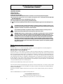
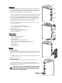
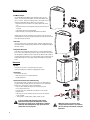
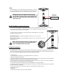
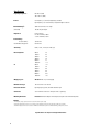
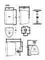
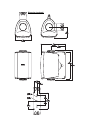
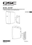
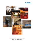
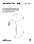
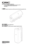
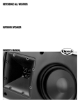
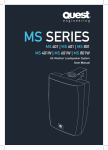
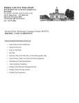
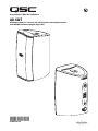
AcousticDesign™ Multi-Use Loudspeaker
AD-S32T
All-Weather 80 mm (3.1”) two-way with shielded woofer and neodymium tweeter
with 70V/100V transformer equipped (bypassable)
*TD-000139-00*
TD-000267-00 rev.A
IMPORTANT SAFETY PRECAUTIONS
& EXPLANATION OF SYMBOLS
1- Read these instructions.
2- Keep these instructions.
3- Heed all warnings.
4- Follow all instructions.
5- Clean only with a dry cloth.
6- Install in accordance with QSC Audio Product’s instructions and a licensed, professional engineer.
7- Do not install near any heat sources such as radiators, heat registers, stoves, or other apparatus (including amplifiers) that produce heat.
8- Only use attachments/accessories from QSC Audio Products, Inc.
9- Use only with mounts or brackets specified by QSC Audio Products.
10- Refer all servicing to qualified personnel. Servicing is required when the apparatus has been damaged in any
way.
The lightning flash with arrowhead symbol within an equilateral triangle is intended to alert the user to
the presence of uninsulated “dangerous” voltage within the product’s enclosure that may be of sufficient
magnitude to constitute a risk of electric shock to humans.
The exclamation point within an equilateral triangle is intended to alert the user to the presence of
important operating and maintenance (servicing) instructions in this manual.
WARNING! Before placing, installing, rigging, or suspending any speaker product, inspect all hardware,
suspension, cabinets, transducers, brackets and associated equipment for damage. Any missing, corroded, deformed or non-load rated component could significantly reduce the strength of the installation,
placement, or array. Any such condition severely reduces the safety of the installation and should be
immediately corrected. Use only hardware which is rated for the loading conditions of the installation
and any possible short-term unexpected overloading. Never exceed the rating of the hardware or equipment. Consult a licensed, professional engineer when any doubt or questions arise regarding a physical
equipment installation.
Warranty (USA only; other countries, see your dealer or distributor)
Disclaimer
QSC Audio Products, Inc. is not liable for any damage to amplifiers, or any other equipment that is caused by negligence or
improper installation and/or use of this loudspeaker product.
QSC Audio Products 3 Year Limited Warranty
QSC Audio Products, Inc. (“QSC”) guarantees its products to be free from defective material and / or workmanship for a period of
three (3) years from date of sale, and will replace defective parts and repair malfunctioning products under this warranty when the
defect occurs under normal installation and use - provided the unit is returned to our factory or one of our authorized service stations via pre-paid transportation with a copy of proof of purchase (i.e., sales receipt). This warranty provides that the examination
of the return product must indicate, in our judgment, a manufacturing defect. This warranty does not extend to any product which
has been subjected to misuse, neglect, accident, improper installation, or where the date code has been removed or defaced. QSC
shall not be liable for incidental and/or consequential damages. This warranty gives you specific legal rights. This limited warranty
is freely transferable during the term of the warranty period.
Customer may have additional rights, which vary from state to state.
In the event that this product was manufactured for export and sale outside of the United States or its territories, then this limited
warranty shall not apply. Removal of the serial number on this product, or purchase of this product from an unauthorized dealer,
will void this limited warranty.
Periodically, this warranty is updated. To obtain the most recent version of QSC’s warranty statement, please visit www.qscaudio.com.
Contact us at 800-854-4079 or visit our website at www.qscaudio.com.
© Copyright 2007, QSC Audio Products, Inc.
QSC® is a registered trademark of QSC Audio Products, Inc.
“QSC” and the QSC logo are registered with the U.S. Patent and Trademark Office
2
Introduction
Thank you and congratulations on your purchase of the AcousticDesign™ AD-S32T multiuse, weather resistant loudspeakers. These products represent the state-of-the-art in allweather, lightweight SR (sound reinforcement) loudspeaker systems. To get the most from
your investment, we encourage you to review this manual carefully.
The AD-S32T loudspeaker systems are full range, high output, two-way designs delivering
superior sound quality and high SPL in a lightweight, weather resistant enclosure. The low
frequency driver is magnetically shielded and the neodymium high frequency driver has
very little stray magnetic field, making the AD-S32T perfect for use near video monitors.
The included ball mount and yoke mount provide secure and versatile installation. These
loudspeakers make an excellent choice for a wide variety of SR applications.
AD-S32T models have a 70V/100V matching transformer and tap selector switch. The
transformer may be bypassed.
The illustration (at right) highlights product features:
1- one set of threaded inserts for yoke mount (top and bottom)
2- transformer tap selector
3- screw terminal style input connectors
4- ball mount attachment point (ball mount removed)
5- safety cable attachment point
What’s Included
The carton contains:
•AD-S32T loudspeaker assembly (2 each)
•Ball mount assembly (2 each)
•Input cover (2 each)
•Input cover gasket (2 each, may be part of cover)
•Input strain relief bushing (2 each, may be part of cover)
•#6-32 x 1/2 long, 4 each pan head Phillips screw (for terminal covers)
•This User Manual
•Yoke mount (2ea)
•Yoke mount knobs (4ea)
Mounting
Stand Alone Mounting
If using the loudspeaker only (no ball mount or yoke mount) the loudspeaker can be set on
any appropriate surface. The cabinet will lean back at a slight angle when set on a flat surface.
When operated at high output levels, the cabinet can vibrate, causing the cabinet to move
or creep if set on a hard surface.
Safety Cable Attachment
On the back of the loudspeaker, near the bottom, is a safety cable attachment point.
Install a safety cable strong enough to support several times the weight of the loudspeaker assembly in the event it may fall. The safety cable should be no more that 1 foot
in length and provide at least 6" in slack.
IMPORTANT! ENSURE THAT THE LOUDSPEAKER IS MOUNTED PROPERLY
AND A SAFETY CABLE IS INSTALLED TO RETAIN THE LOUDSPEAKER IN
THE EVENT OF A MOUNTING FAILURE.
Attach safety
cable here.
Mounting (continued)
Ball Mount Adapter
The included ball mount adapter can be attached to almost any flat
surface. To use the wall mount adapter, secure the wall adaptor using
four to six screws. Ensure the mounting surface is sufficiently strong to
support the loudspeaker and any vibration or seismic activity.
•Connect the shaft of the mount to the speaker. Tighten the locking
nut.
•Connect the wiring to the loudspeaker and install the terminal cover,
if desired.
•Snap the ball mount into the wall adaptor.
•Adjust the angle of the loudspeaker and tighten the knob fully.
The ball mount can also be installed in the top or bottom of the enclosure for
special application use by removing the plastic plugs from the yoke mount screw
holes and following steps above.
Yoke mount
Secure the yoke mount to the mounting surface. Attach the loudspeaker to the
yoke mount using the retaining knobs provided. Aim the loudspeaker and tighten
the knobs securely.
Safety Cable Attachment
On the back of the loudspeaker, near the bottom, is a safety cable attachment
point. Install a safety cable strong enough to support several times the weight of
the loudspeaker assembly in the event it may fall. The cable must be secured to a
secondary support point which is also strong enough to support several times the
loudspeaker’s weight. The safety cable should not be attached to the primary
mount.
Connection
AD-S32T
On the AD-S32T you must set the transformer tap selector
switch to the appropriate setting before applying audio signals.
Terminations
The terminals will accept:
•bare wire (up to 0.10” or 2.59 mm diameter)
•spade lug terminals
Input Connection Cover (wire termination only)
The loudspeaker includes a weather resistant cover for the input terminals.
For proper sealing, the cable jacket must be round (or close to round) and be
between 0.12” (3mm) and 0.2” (5mm) outside diameter.
•Pass the wires through the compression nut, gasket, and cover.
•Loosen the terminal screws.
•Strip the wires 0.39” (10mm) and insert under the screw terminal.
•Tighten screws.
•Slide the cover over the terminals and secure using the two machine
screws provided.
• Ensure gasket is seated properly; tighten compression nut.
To assure weather-tight connections, make sure the
Input Cover fits flush against the loudspeaker cabinet,
all gaskets are properly placed, and hardware is tightened
sufficiently. Use of the Input Cover may require the use of
smaller wire sizes for proper fits.
4
NOTE! You cannot use spade lugs when
the Input Connection Cover is used. Connect
the wires directly to the terminals if using the
Input Cover.
Wiring
Connect the amplifier’s + and - outputs directly to the loudspeaker’s + and - terminals. The screw terminals accept wire or spade terminals. Use only wire connections when using the input cover. The terminals are spaced (0.38”) (9.66 mm).
Maintain proper speaker and amplifier connection polarity
throughout the entire system. All positive-marked loudspeaker terminals should be connected to positive-marked amplifier output
terminals. This will provide the best possible low-frequency output from your system.
AMPLIFIER
AD-S32T 70V/100V Transformer Tap Selection
AD-S32T models are equipped with a 70V/100V matching transformer for distributed audio systems. There is a transformer tap
selector switch on the rear panel for setting the power level of the loudspeaker. The switch may also be set for
8 ohm operation, bypassing the transformer completely.
To select the power level, align the slot with the desired power setting number. Use a coin or flat tip
screwdriver to operate the switch.
70V distributed systems: use the right side markings. Select from 3.8, 7.5, 15, or 30 watts.
100V distributed systems: use the left side markings. Select from 7.5, 15, or 30 watts. the “X” position
should not be used.
NOTE! 8 ohm setting should be used for 8 ohm audio systems only.
Do not use 8 ohm setting when connecting the AD-S32T loudspeaker to 70V/100V distributed audio systems.
Painting the Loudspeaker
The loudspeaker enclosure, grill, and mount can be painted to match any decor, provided the following precautions are observed.
The cabinet is made of high impact polystyrene which requires controlled painting procedures in order to obtain good results. Use a
paint “system” designed for high impact polystyrene from any reputable paint supplier.
1- Remove the grill.
2- If painting mount and loudspeaker as a unit: Attach the ball mount or yoke mount.
3- Mask the loudspeaker’s input connector.
4- Mask the woofer, tweeter, and port being certain not to apply tape directly to the drivers. Alternatively, the outside of the grill can
be completely masked and set in place on the loudspeaker enclosure for painting.
5- Wash the components to be painted with a mild soap and hot water. Be careful not to get water on or into either of the drivers or
the input connections. Rinse with hot water. Allow to dry thoroughly.
6- Scuff-sand the components to be painted using red Scotchbrite® pad or 320 - 400 grit sandpaper.
7- Using compressed air, remove all dust from the components to be painted. Do not blow compressed air directly into either driver.
8- Clean the components to be painted.
9- Using a clean, lint-free, white cloth, wipe the components to be painted with suitable prep solution.
10- Apply primer topcoat.
12- Apply paint.
13- Allow to dry according to paint instructions before handling.
Specifications
Frequency Response :
80- 20k Hz (-6 dB)
75hz -20k Hz (-10dB)
Drivers:
low frequency- 3” (762 mm) magnetically shielded
high frequency- 3/4” titanium dome, neodymium magnet structure
1
Maximum Output :
(calculated)
99 dB SPL continuous rms output
106 dB SPL peak output
Impedance:
8 ohms nominal
6.7 ohms minimum, 300 Hz
31 ohms maximum, 150 Hz
2
Power Rating :
rms (IEC 100 hrs):
recommended amp power:
30 watts rms
60 watts rms
Sensitivity:
85 dB, 1 watt, 1 meter, free field (4 pi)
Directivity Index:
500 Hz
1000 Hz
2000 Hz
4000 Hz
8000 Hz
10000 Hz
500 Hz
1000 Hz
2000 Hz
4000 Hz
8000 Hz
10000 Hz
3
Q:
2.5
4.5
7.0
7.0
2.3
11.4
1.77
2.8
5.0
5.0
5.35
13.8
Weight per pair:
AD-S32T: 4.0 lb. net, 10 lb. shipping
Nominal Coverage:
100° horizontal. x 60° vertical
Enclosure and Grill:
high impact polystyrene, removable aluminum grill
Connectors:
Screw terminal connector for wire, bare wire or spade lugs.
Mounting Hardware:
Included: Ball mount adapter with wall plate and yoke mount with retaining knobs.
NOTES:
1- All frequency ranges specified refer to measured free-field response (4 pi).
2- Calculated maximum peak SPL at 1 m, free-field, speaker operating at rated rms power pink noise input, 50 Hz to 20 kHz.
3- Maximum input power tested in accordance with IEC recommendations; 50 Hz to 20 kHz band limiting, 6 dB signal crest factor.
Specifications are subject to change without notice.
6
Dimensions
Dimensions (continued)
How to Contact QSC Audio Products
Cómo comunicarse con QSC Audio Products
Comment prendre contact avec QSC Audio Products
Kontaktinformationen für QSC Audio Products
联系 QSC Audio Products
Mailing address:
QSC Audio Products, Inc.
1675 MacArthur Boulevard
Costa Mesa, CA 92626-1468 USA
Telephone Numbers:
Main Number
(714) 754-6175
Sales & Marketing
(714) 957-7100 or toll free (USA only) (800) 854-4079
Customer Service
(714) 957-7150 or toll free (USA only) (800) 772-2834
Facsimile Numbers:
Sales & Marketing FAX
(714) 754-6174
Customer Service FAX
(714) 754-6173
World Wide Web:
www.qscaudio.com
E-mail:[email protected]
[email protected]
QSC Audio Products, Inc. 1675 MacArthur Boulevard Costa Mesa, California 92626 USA
©2007, “QSC” and the QSC logo are registered with the U.S. Patent and Trademark Office.