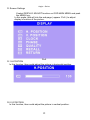
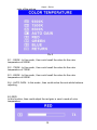
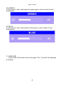
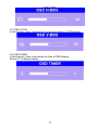
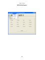
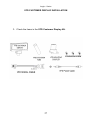
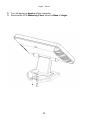
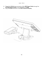
1
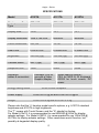
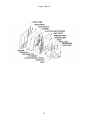
Aegis
Series
Aegis – Series
TABLE OF CONTENTS
Features
3
Specifications
4
Physical Diagrams
5
What comes with Aegis
7
Switch and Controls
8
OSD Settings
9
Installation
19
External Power Adapter
21
MCR Installation
22
MCR Parameter Modification
25
VFD Customer Display Installation
27
Trouble Shooting
32
1
Aegis – Series
The information in this document is subject to change without prior notice in
order to improve reliability, design and function and does not represent a
commitment on the part of the manufacturer. In no event will the manufacturer
be liable for direct, indirect, special, incidental, or consequential damages
arising out of the use or inability to use the product or documentation, even if
advised of the possibility of such damages.
MonitorMice is a registered trademark of Elo Touchsystems
2
Aegis – Series
FEATURES
¾
Cast aluminium front and base construction - rugged and durable
¾
Compact size and small footprint - fits where space is at a premium
¾
Standard VGA for easy interface to a standard PC VGA port.
¾
Flicker-free LCD display - easy on the eyes
¾
Low radiation - poses less hazard to user’s health
¾
Power-thrift - environmentally friendly
¾
Tiltable display - adapts to placement, user position and lighting
conditions
¾
VESA mounting holes - fits optional tilt/swivel wall mount fixtures
¾
Flexible power options - tap power from the computer or use an
external adapter
¾
Point of sales industry specific options - touch screen, VFD customer
display, magnetic card reader
3
Aegis – Series
SPECIFICATIONS
Model
A152TA
A121TA
A122TA
TFT LCD
TFT LCD
TFT LCD
Display Area
15.00”
12.1”
12.1”
Display Resolution
1024 x 768 XGA
800X600
800X600
Colour Resolution
262,144
16.7M
16.7M
Pixel Pitch
0.297x 0.297
0.306X0.306
0.306X0.306
Brightness
350 nits (typ)
150 nits (typ)
300 nits (typ)
Contrast Radio
400:1 (typ)
150:1 (typ)
200:1 (typ)
Response time
16ms
40ms
20ms
Display
Type
Panel
Interfaces
cables & connectors
Energy Saving Mode
Standard VGA for
use with a Video
Graphic Adapter
Model specific options:PS/2 for MCR & 32 Keyboard,
RS232 for touch screen, DC
power.
VESA DPMS compliant
Power Supply
A152TA=12v @ 4A and A12xTA=12v @2A
Weight
A152TA=6.4 kg and A12xTA= 5.5 Kg
Please note that the “x” denotes model specific options, e.g. A121TA standard
brightness and A122TA is high brightness.
The “T” means with Touch Screen, and the “A” stands for Analog.
For Model A12xTA, it is recommended to use 800X600 @ 60Hz for display
adapter settings. For Model A152TA, it is recommended to use 1024x768 @
60-75Hz for display adapter settings. Other resolutions would function, but
possibly at degraded display quality.
4
Aegis – Series
PHYSICAL DIAGRAMS
A12xTA
A152TA
5
Aegis – Series
6
Aegis – Series
WHAT COMES WITH AEGIS
Upon unpacking, please inspect to make sure all items are in place and in
good condition. If there is any damaged or missing item, please contact your
dealer immediately.
The following items come as standard
1. LCD Display unit with tilt base
2. Power bracket
3. DC power cable 9000XC1594
4. User’s manual
5. Driver CD for Elo touch screen
Aegis
7
Aegis – Series
SWITCH AND CONTROLS
Model A152TA / A12xTA has built-in OSD (on screen display) controls to
adjust various display parameters. The control buttons are located on the
bottom of the back cover.
OSD Controls
8
Aegis – Series
OSD SETTINGS
There are four buttons on OSD panel: Menu / Enter, Right, Left and LCD
ON/OFF. The functions of these four buttons are as follows
Menu/Enter Button
Press it to open OSD window and enter user mode to do the
function adjustment or selection of the item. It may have many levels
in one item. As you select this kind of item, you will enter the next
level and see the sub-items.
Right Button
Press it to Scroll item Right or to decrease the value or to switch the
selected item to another.
.
Left Button
Press it to Scroll item Left or to increase the value or to switch the
selected item to another.
).
LCD ON/OFF Button
Control LCD ON/OFF button
9
Aegis – Series
OSD Menu Structure
Main Menu
If push the “ MENU” key the screen will appear this main menu page, you
can use the “UP” or “ADJ. +” AND “Down” or “ADJ. –“ key ( appear Pic1 )
to select the function you need.
Pic1
The end of this page will be shown the working resolution and frequency.
A.Auto Ad jus t
If select this function on OSD MAIN MENU and push the MENU key.
( appear Pic2 )
In this function, that will be activated the auto adjusting for the
picture.
Auto Adjust
Pic2
10
Aegis – Series
B..BRIGHTNESS
If select BRIGHTNESS function on OSD MAIN MENU and push the
MENU key.
( appear Pic3 )
You can push ADJ+ or ADJ- key to increase or decrease backlight
current of the inverter.
Pic3
C. CONTRAST
If select CONTRAST function on OSD MAIN MENU and push the
MENU key. ( appear Pic4 )
You can push ADJ+ or ADJ- key to increase or decrease video gain of
the picture.
Pic4
11
Aegis – Series
D. Screen Settings
If select DISPLAY ADJUST function on OSD MAIN MENU and push
the MENU key.
In this mode, that will into the sub-page ( appear Pic5 ) to adjust
display’s function of the picture.
Pic5
D-1 H-POSTION
In this function, than could adjust the picture in horizontal position.
D-2 V-POSITION
In this function, than could adjust the picture in vertical position.
12
Aegis – Series
D-3 CLOCK
In this function, than could adjust the clock frequency of the picture.
D-4 PHASE
In this function, than could adjust the clock phase of the picture.
D-5 QUALITY
In this function, than could adjust the scanning filter of the picture.
E. COLOR TEMPERATURE
If You select COLOR TEMPERTURE function on OSD MAIN MENU
and push the MENU key.
In this function, that will into the sub-page ( appear Pic6 ) to adjust the
display
13
Aegis – Series
color of the picture
Pic 6
E-1 : 9300K : In this mode , than could recall the value for the color
temperature of 9300K.
E-2 : 7500K : In this mode , than could recall the value for the color
temperature of 7500K.
E-3 : 6500K : In this mode , than could recall the value for the color
temperature of 6500K.
E-4 : AUTO GAIN : In this mode , than could active the auto white balance
adjusting.
E-5 RED
In this function, than could adjust the red gain in user’s mode of color
temperature.
14
Aegis – Series
E-6 GREEN
In this function, than could adjust the green gain in user’s mode of color
temperature.
E-7 BLUE
In this function, than could adjust the blue gain in user’s mode of color
temperature.
F. LANGUAGE
In this mode, that could into the sub-page ( Pic7 ) to select the language
for display.
15
Aegis – Series
Pic 7
G.OSD DISPLAY
If select OSD DISPLAY function on OSD MAIN MENU and push the
MENU key.
this function will into the sub-page ( Pic8 ) to adjust the display’s
function for OSD.
Pic8
G-1 : OSD H-POS
In this function, than could adjust the horizontal position of OSD display.
16
Aegis – Series
G-2 OSD V-POS
In this function, than could adjust the vertical position of OSD display.
G-3 OSD TIMER
In this function, than could adjust the time of OSD display.
Except “0” is always display.
17
Aegis – Series
G-4 OSD TRANSPARENCY
In this function, than could adjust the transparency of OSD display
H. VGA / DVI INPUT
If select VGA/DVI function on OSD MAIN MENU and push the MENU key.
In this function, that will into the sub-page ( appear Pic9 ) to select input
source.
Pic9
H-1 : ANALOG INPUT : In this mode , than could select the input source from
the VGA.
H-1 : DIGITAL INPUT : In this mode , than could select the input source from
the DVI.
18
Aegis – Series
INSTALLATION
Model A152TA / A12xTA
This model uses a standard VGA interface.
1. Turn off the computer.
2. Put the Aegis on a steady surface.
3. Please refer to Power Adapter section for instruction on using an external
power adapter and skip this step.
For powering from the computer through the Power Bracket:
a. Open the computer case.
b. Secure the Power Bracket to an unused expansion slot bracket
location.
c. Connect the connector on the Power Bracket wire assembly to a
matching one from computer power supply.
d. Close the computer case.
e. Connect the Aegis Power Cable to the connector on the
Power Bracket.
4. Connect the VGA Cable to the VGA port on the computer.
5. For the unit with touch screen function, please connect the Cable and
DSUB9 Connector to a COM port (RS-232C port) on the computer. Please
note which port number it is connected to, this information is required for
touch driver installation.
6. For units with MCR (magnetic card reader) option. Connect the KB
Cable to the PS/2 keyboard port on the computer. If a keyboard is to be
used, plug the connector from your keyboard into the spare female KB
Connector on the Aegis Keyboard Cable.
19
Aegis – Series
20
Aegis – Series
EXTERNAL POWER ADAPTER
For situation where the Power Bracket cannot be used to power the Aegis,
an optional External Power Adapter can be used instead.
1. Check the items in the External Power Adapter kit, including a power
adapter and an AC cord.
2. Turn off power to the computer and turn the Aegis power switch to off.
3. Plug one of the Power Adapter plug to the Aegis Power Connector.
4. Connect the AC plug of the Power Adapter to an AC outlet.
21
Aegis – Series
MCR INSTALLATION
The MCR (magnetic card reader) option can be fitted to the right side of
Aegis. This option allows the reading of magnetic stripe card through
keyboard input.
* If there is a need to modify the MCR parameters, such as country code and
track combination, please follow the instruction in the section, MCR
Parameter Modification.
22
Aegis – Series
1. Check the items in the MCR option kit.
2. Turn off Power to the Aegis and the computer.
3. Unplug the loopback from the MCR socket. The MCR Socket
is found on the right side on the back of the main Unit
23
Aegis – Series
4. Attach the MCR Assembly to the main unit and connect the MCR
cable to the MCR socket.
5. Secure the MCR to the main unit with 2 screws.
6. Turn on Aegis power.
7. Put the back cover on Aegis and secure with screws.
* If the MCR is taken off, the loopback plug must be re-inserted.
Otherwise, the keyboard would not function.
24
Aegis – Series
MCR Parameter Modification
This option is for users who need to customize the MCR parameters for a
particular task.
Some of the useful parameters include:
The selection of country code, other than the default English.
The choice of track combinations.
The preamble/postamble codes.
The MCR parameters can be modified by using the supplied utility program.
The utility can be found on the CD that came with your system in the “Utilities”
folder. The program name is msr_v12_win.zip.
If you are upgrading and earlier system to include our MCR reader, then this
utility
can
be
located
on
our
website
at
http://www.firich.com.tw/tech_drivers.htm in the section labelled as “MSR
Utility”.
Unzip this file onto your system hard disk, in a folder of your choice.
It will also create 3 subfolders named Disk1, Disk2, and Disk3.
Change to the folder “Disk1” and run the “Setup.exe” program, and follow the
simple onscreen instructions.
When the installation finishes, you will find that a new folder has been created
in your “Program files” folder, labelled as “Decoder” with a subfolder named
“S64 Decoder”
Now change folder to C:\Program Files\Decoder\S64 Decoder and run the
program named “S64_cfg.exe”
When the program has loaded please select the Magnic_Reader menu item
as in the following picture. By using the 3 top items listed; Interface,
Communication, and Miscellaneous, you will be able to alter many of the
parameters associated with the MCR unit.
When you have finished your modifications and are sure that they are set
exactly how you want them to be, just click on the menu item Transmit to
download the new parameter to the MCR unit. Please refer to the Help menu
for any further assistance.
25
Aegis – Series
MCR Utility Reader
26
Aegis – Series
VFD CUSTOMER DISPLAY INSTALLATION
1. Check the items in the VFD Customer Display Kit.
27
Aegis – Series
2. Turn off power to Aegis and the computer.
3. Remove the VFD Mounting Cover from the Base of Aegis.
28
Aegis – Series
4. Secure the VFD Mounting Coupler to the Base with three VFD Mounting
Screws.
29
Aegis – Series
5. Thread the RJ-45 phone connector of the VFD Signal Cable through the
VFD Mounting Coupler, from the bottom of Aegis.
6. Plug the RJ-45 connector to the VFD Customer Display.
30
Aegis – Series
7. Fit the VFD Customer Display onto the VFD Mounting Coupler.
8. Plug the DB9F connector of the VFD Signal Cable to a COM port on the
computer.
9a. For powering from the computer.
a. Plug the 3 pin connector of VFD Power Cable to one of the connector
on the Power Bracket.
b. Plug the other end of the VFD Power Cable to the DC Jack on the
DB9F connector of the VFD Signal Cable.
9b. For powering using an external AC adapter.
a. Plug the DC plug from the AC adapter to the DC Jack on the DB9F
connector of the VFD Signal Cable.
b. It is Important that only an AC adapter made specifically for this VFD
Customer Display is used. Other AC adapters, even with the same
DC Plug, if used may cause damage to the Customer Display and,
possibly, the computer as well.
31
Aegis – Series
TROUBLE SHOOTING
When encountering difficulties in using this product, please follow the steps
below. If the problem persists, please contact the dealer.
1. No picture on screen
a. Check the AC cord and signal cable. Make sure they are properly
connected.
b. Check that the power button on the OSD panel is turned on.
c. Check if the computer has entered energy saving mode.
2. Abnormal display colour
a. Check if the signal cable is properly connected to the computer.
b. For model A152TA / A12xTA, using the on-screen-adjustment
mode to adjust the colour parameters.
3. Skewed or distorted display
a. Check if the signal cable is properly connected to the computer.
b. For model A152TA /A12xTA, using the on-screen-adjustment
mode to adjust the geometric parameters.
4. Picture too large or too small
a. Check if the display resolution is set correctly in the operating system.
b. For model A152TA / A12xTA, using the on-screen-adjustment mode
to adjust the size parameters.
5. Touch screen does not work
a. Check if the COM port cable is properly connected to the computer.
b. Check if the Elo touch driver has been loaded properly.
c. Check if the COM port number is set correctly.
6. VFD Customer Display does not display properly
a. Check if the power cable is connected properly.
b. Check whether the power switch is turned on.
7. Magnetic Card Reader does not work
a. Check if the KB Connector is properly connected to the computer’s
PS/2 port.
8. The card swipe character(s) is incorrect or shows random characters
a. The country code parameter setting may need modification, please
refer to the section, MCR Parameter Modifications.
32