1
YAMAHA DIAGNOSTIC SYSTEM VERSION 2.00 INSTRUCTION MANUAL 6CL-2819U-10 Preface Preface This Instruction Manual, written for use by Yamaha outboard motor and watercraft dealers, contains information on using the YAMAHA Diagnostic System software and diagnosing problems in an outboard motor or watercraft. This manual contains information to be used together with basic servicing procedures, and therefore requires that the person performing these procedures have a basic maintenance knowledge and technical skills of outboard motors or watercraft. See the applicable outboard motor or watercraft service manual for detailed service and maintenance information. The information included may be subject to change for improvement. Trademark Acknowledgments IBM is a registered trademark of International Business Machines Corporation. Microsoft and Windows are registered trademarks of Microsoft Corporation. All other brand or product names are trademarks or registered trademarks of their respective companies or organizations. YAMAHA DIAGNOSTIC SYSTEM VERSION 2.00 INSTRUCTION MANUAL © 2011 Yamaha Motor Co., Ltd. 1st Edition, August 2011 All rights reserved. Any reprinting or unauthorized use without the written permission of Yamaha Motor Co., Ltd. is expressly prohibited. Important Information Important Information Particularly important information is distinguished in this manual by the following notations: The Safety Alert Symbol means ATTENTION! BECOME ALERT! YOUR SAFETY IS INVOLVED! A WARNING indicates a hazardous situation which, if not avoided, could result in death or serious injury. A NOTICE indicates special precautions that must be taken to avoid damages to the outboard motor, watercraft, or other property. A TIP provides key information to make procedures easier or clearer. Outboard Motors Outboard Motors Abbreviation The following abbreviations are used in this Instruction Manual and on the YAMAHA Diagnostic System screen. While not included in this table, some names displayed on the YAMAHA Diagnostic System screen have a restriction on the numbers of characters, and are therefore abbreviated. Abbreviation Abbreviation APS C Description Abbreviation Description Abbreviation Accelerator Position Sensor ISC Idle Speed Control Center LPS Lever Position Sensor ECM Electronic Control Module ETV Electronic Throttle Valve N OCV S Neutral SPS STBD Description Starboard side Shift Position Sensor Starboard side Oil Control Valve TPS Throttle Position Sensor EX Exhaust P Port side VCT Variable Camshaft Timing F Forward PORT Port side YDIS YAMAHA Diagnostic System IDM IN Ionic current Detection Module PTT R Intake Power Trim and Tilt R/C Reverse Product names for each market The following names are used in each market. Meter names for each market North America Worldwide 6Y8 Meter Command Link Multifunction Meter 6Y8 Multifunction Meter 6Y9 Color Gauge Command Link Plus Multifunction Color Gauge 6Y9 Multifunction Color Gauge 6Y8 Meter system Command Link Digital Network (6Y8 Meter) 6Y9 Color Gauge system Command Link Plus Digital Network (6Y9 Color Gauge) Remote Control (Digital Electronic Control) Contents Contents Introduction...................................................................................................1 1. Features............................................................................................ 1 1-1. Functions by data transmission type.................................................. 2 1-2. Transmission Method......................................................................... 4 ■■ CAN-Line.................................................................................... 4 ■■ K-Line......................................................................................... 6 1-3. Newly added functions....................................................................... 7 ■■ Input Setting................................................................................ 7 ■■ Logging. ..................................................................................... 8 ■■ CAN Information. .......................................................................11 2. Compositions of the tool.................................................................. 12 3. Hardware requirements................................................................... 13 4. Compatible models.......................................................................... 15 5. Languages...................................................................................... 16 Installation...................................................................................................17 1. Before installation............................................................................ 17 2. Installing the YAMAHA Diagnostic System........................................ 18 Connecting the computer to the outboard motor....................................25 1. Basic connections...........................................................................26 2. When logging..................................................................................27 3. When viewing input values using external devices............................28 Starting the YAMAHA Diagnostic System.................................................30 Quitting the YAMAHA Diagnostic System.................................................31 Screen specifications.................................................................................32 1. Standard screen..............................................................................32 1-1. 1-2. 1-3. 1-4. Title area......................................................................................... 32 Status area..................................................................................... 33 Main area........................................................................................ 33 Button area..................................................................................... 34 2. Sub screen......................................................................................34 Common operations...................................................................................35 1. Selecting the display items...............................................................35 1-1. Display items................................................................................... 35 1-2. Display order................................................................................... 37 2. Setting the graph properties.............................................................38 2-1. Display range.................................................................................. 39 2-2. Display colors...................................................................................41 3. Saving data.....................................................................................44 3-1. Data save....................................................................................... 44 3-2. Data export..................................................................................... 45 4. System Info. button..........................................................................46 5. Message button...............................................................................47 6. Select Eng. button...........................................................................47 7. Back button.....................................................................................49 Update..........................................................................................................50 Setting..........................................................................................................52 Engine..........................................................................................................53 1. Diagnosis........................................................................................53 1-1. Diagnosis........................................................................................ 55 1-2. Diagnosis Record............................................................................ 57 ■■ Deleting diagnosis record in the ECM. ....................................... 59 1-3. Engine Record................................................................................ 60 1-4. Engine operating hours.................................................................... 62 2. Engine Monitor................................................................................63 2-1. Digital Display.................................................................................. 64 2-2. Graph Display.................................................................................. 65 ■■ Saving graph data..................................................................... 66 2-3. Input Setting.................................................................................... 68 3. Component Test..............................................................................70 3-1. Stationary Test................................................................................ 70 ■■ Ignition coil activation test.......................................................... 72 ■■ Injector activation test................................................................ 74 ■■ Electric fuel pump activation test................................................ 75 ■■ Low-pressure fuel pump activation test...................................... 76 ■■ Oil plunger pump activation test................................................. 77 ■■ ISC valve activation test............................................................ 79 ■■ OCV activation test................................................................... 80 3-2. Active Test.......................................................................................81 ■■ Cylinder drop test...................................................................... 82 ■■ Fully open ISC valve test........................................................... 83 ■■ Fixed ISC valve opening angle test............................................ 84 Contents 4. Data Logger....................................................................................85 4-1. Logger graph................................................................................... 85 4-2. ECM Record graph.......................................................................... 87 4-3. Logging............................................................................................91 ■■ Clearing data from the adapter.................................................. 92 ■■ Record Setting.......................................................................... 93 ■■ Displaying data in a graph. ........................................................ 96 Boat System................................................................................................97 1. Tilt limiter.........................................................................................98 ■■ Setting the tilt limiter.................................................................. 98 ■■ Resetting the tilt limiter setting. .................................................100 2. Digital Electronic Control System................................................... 103 ■■ Resetting the Digital Electronic Control System.........................103 Maintenance..............................................................................................105 1. Record of engine oil change.......................................................... 105 CAN Information........................................................................................107 1. Communication List....................................................................... 107 2. Bus Statistics.................................................................................111 Off-line........................................................................................................113 Appendix....................................................................................................115 1. Setting the desktop area................................................................ 115 2. Uninstalling the YAMAHA Diagnostic System.................................. 117 3. Troubleshooting............................................................................. 118 Functions by model (Outboard motor)....................................................119 Introduction Introduction The YAMAHA Diagnostic System uses precision fault diagnosis to offer better serviceability at a time when there is increasing demand for service tools for electronically controlled products. It provides quick, reliable, safe, and reasonable service, and is intended to obtain customer satisfaction. The YAMAHA Diagnostic System features updated software and expanded tool functions that allow it to respond to new models and technologies, maintaining compatibility with regulations. 111 Features YAMAHA Diagnostic System Version 2.00 covers most of the functions of the Version 1 series. (Not interchangeable) The CAN-Line transmission method has been added to the conventional transmission method (K-Line), and this enables diagnosis of multiple engines. New functions of Input Settings, Logging, and CAN Information have been added. 1 Introduction 11111 Functions by data transmission type Composition and function-specific characteristics of YAMAHA Diagnostic System Version 2.00 are as per the list below. Menu Primary Function What You Can Do Transmission Method CAN-Line Top Menu Start Main Menu Engine 2nd-level Menu 6Y9 Color Gauge hub 6Y8 Meter hub YES(*1) — YES YES(*1) — YES Check the engine trouble history. YES(*1) — YES Engine Displays operating hours by RPM. operating hours by RPM Check the history of engine usage. YES(*1) — YES Digital Display Displays ECM data numerically. Check the current operating state of the engine. YES(*1) — YES YES(*1) — YES Settings to display data from connected View data from external external devices on YDIS screen. devices on YDIS. YES — YES Component Stationery Test Test Performs an operational test of each component with the engine stopped. YES — YES Active Test Performs an operational test of each component with the engine running. YES — YES Diagnosis Engine Monitor 3rd-level Menu Comparison K-Line to Version 1.33 Diagnosis Displays results of current fault diagnosis. Diagnosis Record Displays a history of fault diagnosis recorded in the ECM. Engine Record Displays the engine state recorded in the ECM. Identify abnormalities. Graph Display Displays ECM data in graph form. Input Setting (*1) Items that enable diagnosis for multiple engines. 2 Check functioning of each component. New Introduction Menu Primary Function What You Can Do Transmission Method CAN-Line Top Menu Start Main Menu Engine Boat System 2nd-level Menu Data Logger 3rd-level Menu 6Y9 Color Gauge hub 6Y8 Meter hub Comparison K-Line to Version 1.33 Record Set Displays a graph of past data recorded Check the past operating in the ECM. state of the engine. YES — YES Show Data Displays a graph of data recorded before and after troubles. YES — YES Logging Displays a graph of data recorded on the adapter. YES — YES YES — YES YES — YES Tilt Limiter Sets the tilt angle when the outboard motor is tilted up. R/C System Reset Returns connection between the outboard motor and the Digital Electronic Control to default settings. Maintenance Engine oil change record Configure systems. Records oil change history. Manage oil change history. YES — YES Update Update database. Update database. YES — YES Setting Sets the language and units displayed on YDIS screen. Switch screen displays. YES — YES(*2) Off Line Displays data saved on the computer, when the ECM is disconnected. Check data saved on computer without connecting to ECM YES — YES CAN Communication List Information Displays quality of CAN system device connection and transmission. Distinguish the type of device connected. YES YES — YES YES — Bus Statistics Displays the transmission load ratio for Check whether devices the CAN system. are connected correctly. (*2) When connected via K-Line, you cannot select display units. 3 New New New Introduction 11111 Transmission Method Two transmission methods have been added to YAMAHA Diagnostic System Version 2.00. The CAN-Line in which the transmission harness is connected to a hub, and the K-Line, in which a transmission harness is connected to the outboard motor, which is the same as in the YAMAHA Diagnostic System Version 1 series. ■■ CAN-Line There are two types of CAN-Line, the 6Y9 Color Gauge system, and the 6Y8 Meter system. By being connected to a computer using a hub, this enables operation of the YAMAHA Diagnostic System from near the driver’s seat, preventing moisture damage to the computer and peripherals. The 6Y9 Color Gauge system enables display of results of diagnosis for multiple engines. The 6Y8 meter system can use only CAN Information functions. 6Y9 Color Gauge system a b f e g c d a Computer b Adapter e 6Y9 Color Gauge f Y-COP c Outboard motor d Hub g Digital Electronic Control 4 Introduction 6Y8 Meter system a b e f e c d a Computer b Adapter d Hub e 6Y8 Meter c Outboard motor f Y-COP 5 Introduction ■■K-Line K-Line connections can use functions other than CAN Information and unit selection in the Setting. As previously, this connects the coupler on the outboard motor to the computer, and performs diagnostics for individual engines. a b c a Computer b Adapter c Outboard motor 6 Introduction 11111 Newly added functions ■■ Input Setting Connect external devices such as A/F and fuel pressure sensors, and specify equipment names and units to enable display on the Engine Monitor and logging of these values. This can convert voltage values input from external devices to arbitrary values, and input these as 4ch. Channels 1–3 support input voltage of 0–5 V, and channel 4 supports input voltage of 0–20 V. Please use commercially-available external devices. 7 Introduction ■■Logging With the YAMAHA Diagnostic System Version 2.00, you can record data in the adapter. After configuring recording properties in the adapter while the computer and engine are connected, removing the USB cable from the adapter records data in the adapter. These data can be displayed in graph form on the YAMAHA Diagnostic System monitor. With this system, the computer and engine are not connected during logging. Accordingly, because operating conditions can be recorded by placing the adapter inside the cowling, it will be easier to reproduce trouble conditions, and to investigate the causes of any faults. •• Removing the USB cable connected to the computer from the adapter starts recording. Connecting the USB cable to the adapter stops recording. •• Recording normal data (while in default condition) enables comparison with fault data, and makes it easier to investigate causes of faults. •• In the future, addition of the function by which logging can be stopped through use of the trigger switch harness and switch extension harness is expected. Conceptual diagram of Logging a d b e b c b c f a Disconnect the USB cable from the adapter. b Recording (engine speed: 500r/min or more) d Connect the USB cable to the adapter. e Fault occurs. c Stop recording (engine speed: less than 500r/min) f Adapter recording status 8 Introduction •• The adapter is able to record data in 1.6 MB of memory under preconfigured conditions. •• The green LED on the adapter indicates the power status. The red LED indicates it is recording. •• During operation, the adapter is supplied power from the engine. If the engine is stopped while the adapter is recording, then the rechargeable battery within the adapter will perform a backup. (Guaranteed for 48 hours with the battery charged for an hour) •• If the internal battery becomes depleted, recorded data will be deleted. Accordingly, before this happens save the data or connect the adapter to the engine and recharge the battery. •• During logging, ensure the waterproof cap is on the USB cable port. d c a a Red LED b Green LED b c Waterproof cap d USB cable 9 Introduction Adapter LED lighting patterns LED Status Adapter Status (Normal logging condition) Description Green LED Red LED □□□□□□□□ (OFF) □□□□□□□□ (OFF) Normal Power OFF The adapter is not being supplied with power. ■■■■■■■■ (ON) ■■■■■■■■ (ON) Normal Normal logging not set Data recording completed Connected to computer If normal logging is not being used, if recording is completed, or if connected to the computer. ■■■■■■■■ (ON) ■■□□■■□□ (0.5 sec. ON, 0.5 sec. OFF) Normal Recording data If engine speed is 500 r/min or more, and communication established with the ECM. ■■■■■■■■ (ON) ■■■■□□□□ (1 sec. ON, 1 sec. OFF) Normal Stopping data recording If engine speed is less than 500 r/min, and communication established with the ECM. ■■■■■■■■ (ON) ■■□□■■□□ (0.05 sec. ON, 0.05 sec. OFF) llllllllllllllllllllllllllllllllllll Abnormal Transmission error (0.05 sec. ON, 0.05 sec. OFF) □□□□□□□□ (OFF) Abnormal Adapter firmware (internal software) abnormality 10 If communications cannot be established with the ECM. Cause: The engine power is OFF. The transmission harness or USB cable is disconnected. Connected to a different engine to that set for recording. Recording set to use a K-Line, but a CAN-Line is connected. Recording set to use a CAN-Line, but a K-Line is connected. Response: Check the harness, cables, and other connections. Error in updating the adapter firmware (internal software). Cause: Data erased, or a USB cable removed while setting recorded values, etc. Response: Close YAMAHA Diagnostic System, check connections, then restart. Introduction ■■ CAN Information CAN Information has two functions; Communication List and Bus Statistics. With the Communication List, you can know whether or not a device is correctly connected. If the device is correctly connected, then detailed device information will be displayed. Bus Statistics displays the status of CAN bus devices correctly connected, and the bus load rates. a c a b c d d b 11 Introduction 222 Compositions of the tool YAMAHA Diagnostic System Version 2.00 is made up of 10 components. h a e b i f c d g j a CD-ROM (software + Instruction Manual) f K-Line harness b Adapter g AD harness (for external input) c Adapter cap h Power supply harness d USB cable(5 m) e CAN-Line harness i Trigger switch harness j Trigger switch extension harness 12 Introduction 333 Hardware requirements It is recommended that the computer upon which this software will be installed meets the following conditions. PC: IBM PC/AT compatible PC with a Microsoft Windows Operating System. Operating system: Microsoft Windows XP Professional SP3 (32 bit), Windows Vista Business SP2 (32 bit), Windows 7 Professional SP1(32 bit/64 bit) CPU: Windows XP: Pentium, 1 GHz or higher Windows Vista: Intel processor, 1.6 GHz or higher Windows 7 (32 bit): 1.6 GHz or higher 32-bit (x 86) processor Windows 7 (64 bit): 1.6 GHz or higher 64-bit (x 64) processor Memory: Windows XP: 512 MB or more Windows Vista: 1 GB or more Windows 7 (32 bit): 1 GB or more Windows 7 (64 bit): 2 GB or more Hard disk free space: Windows XP: 1.5 GB or more Windows Vista: 15 GB or more Windows 7 (32 bit): 16 GB or more Windows 7 (64 bit): 20 GB or more Drive: CD or DVD-capable drive 13 Introduction Display: XGA (1024 x 768 pixels) or more, 16.7 million or more colors Input devices: Mouse, keyboard, and touch panel that are compatible with the operating systems mentioned above Communication port: USB port (USB 2.0 or 1.1) Printer: Compatible with the operating systems mentioned above •• Operating speed may drop, depending on your computer. •• The amount of memory and hard disk space may differ depending on your system environment. Using this system when there is little hard disk space available may cause memory shortages and other troubles. •• Some functions may not operate correctly even when used on computers using one of the compatible operating systems due to limitations applied by a computer manufacturer. •• Use a small font as a system font. •• Before starting YAMAHA Diagnostic System every first time after turning on the computer, quit any other applications that are running. •• Do not use the screen saver, power saving, or stand-by function. Communication may be cut off and YAMAHA Diagnostic System reset may be required. •• Only one device (one computer to one adapter) can be tested, even when multiple adapters are connected to multiple USB ports on the computer. •• Be sure to end this program if the login user is changed. •• Do not use a USB hub. •• Starting this software base may cause the adapter firmware to update. •• Do not change the screen size when using this software. 14 Introduction 444 Compatible models This software is compatible with the following models: North American models Engine type Model name 3 (L)Z150, VZ150, Z175, VZ175, (L)Z200 2596 cm HPDI 3342 cm3 VZ200, VZ225, (L)Z250, VZ250, (L)Z300, VZ300 L3 L4 L4 L4 L4 V6 V6 Bass V6 V8 747 cm C 1741 cm3 (L)F115 F75, F90 3 F50, T50, F60, T60, F70 1596 cm 996 cm B F40 (EFI models) 3 –’00 D ’01– E E 2670 cm3 (L)F150A 3 3352 cm Model group (*1) A HPDI 3 Model year F (L)F200, (L)F225 G (L)F200, F225TLR, (L)F250 (ETV models) H (L)F250B (Digital Electronic Control) I 3 VF200, VF225, VF250 J 3 (L)F225, (L)F250, (L)F300 4169 cm 4169 cm K 5330 cm3 (L)F300, (L)F350 (*1) For details of each model group, see “Functions by model (Outboard motor)” 15 ’08–’10MY L ’11MY M Introduction Worldwide models Engine type HPDI HPDI L3 L4 L4 L4 L4 Model name Model year 2596 cm3 (L)Z150P, Z150Q, Z175G, Z175H, (L)Z200N, Z200P, Z200Q 3 3342 cm 747 cm3 B F30B, F40F C F40D, F40G E 3 F75B, F75C, F80B, F80C, F90B, F100D 3 F50F, FT50G, F60C, FT60D, F70A 996 cm A Z200R, Z225H, Z240A, Z240B, (L)Z250D, Z250F, (L)Z300A, Z300B 1741 cm3 F(L)115A 1596 cm –’00 D ’01– E E 2670 cm3 F(L)150A , F(L)150B 3 Model group (*1) F F(L)200A, F(L)200B, F(L)225A G F(L)200C, F(L)225B, F225C, F(L)250A, F(L)250G H V6 3352 cm V6 Bass 4169 cm3 F200D, F225D, F225G, F250C, F250F, F275A J V6 4169 cm3 F(L)225F, F(L)250D, F(L)300B K V8 5330 cm3 F(L)300A, F(L)350 F(L)250B I ’08–’10MY L ’11MY M (*1) For details of each model group, see “Functions by model (Outboard motor)” Previously sold models that are compatible with the YAMAHA Diagnostic System can also be used with Version 2.00. 555 Languages This software supports the following languages: English, French, Spanish, and Japanese Blank spaces are left so that other languages can be added as it becomes necessary in the future. 16 Installation Installation This section provides information on installing the YAMAHA Diagnostic System on your computer. This explanation assumes that you are installing in a Windows 7 environment. Where necessary, screenshots from Windows XP or Windows Vista will be used. 111 Before installation To use the YAMAHA Diagnostic System, the required component and device drivers must be installed at the same time as the Diagnostic System. These will be installed automatically by the installer. Required components: [. NET Framework 3.5 SP1] or later, [Windows Installer3.1] or later. The required components are pre-installed in Windows 7. Before installing the YAMAHA Diagnostic System, make sure that your computer meets the specified requirements. For detailed information on the system requirements, see “Hardware requirements.” Start installation without the adapter connected to the computer, and then connect the adapter to the computer when installing the device drivers. It is strongly recommended that you quit all other programs before running the installer. 17 Installation 222 Installing the YAMAHA Diagnostic System Install in the following order: Install required components Install YAMAHA Diagnostic System e Install device drivers For Windows 7, the required components are already installed, so begin by installing the YAMAHA Diagnostic System. 111 222 333 444 555 Turn on your computer. Insert the YAMAHA Diagnostic System CD-ROM into the CD-ROM drive of the computer. Double-click the Computer (My Computer) icon, and then the CD-ROM drive icon to start up the installer. If installing on a 32-bit OS, double-click the folder labeled [32bitEdition]. If installing on a 64-bit OS, double-click the folder labeled [64bitEdition]. Double-click the [setup] icon. 18 Installation 666 777 The installer will automatically install the required components if they are not installed. If these components are already installed, proceed to step 8. The License agreement screen will appear. If you accept the terms of the agreement, click [Accept] to continue. •• If a dialog box prompting you to restart the computer appears, click [Yes] to restart the computer. •• If you are using Windows Vista and the User Account Control dialog box appears, click [Continue] to continue. •• In the following cases, an error message will appear and the installation will be canceled. • When attempting to install the 32-bit version on a 64-bit version of Windows 7. • When attempting to install the 64-bit version on a 32-bit version of Windows XP, Windows Vista, or Windows 7. 888 The YAMAHA DIAGNOSTIC SYSTEM2 Setup Wizard appears. Click [Next] to continue. 19 Installation 999 The Customer Information window appears. Enter the Name, Organization, and Install key number, and then click [Next]. •• Entering the wrong Install key number will cause an error message to appear and cancel the installation. •• The Install key number is printed on the back page of the CD-ROM booklet. 1111The Confirm Installation window appears. Click [Next] to start the installation process. 1111If you are using Windows Vista or Windows 7 and the User Account Control dialog box appears, click [Yes] to continue. 20 Installation 1111After the installation is completed, the Installation Complete dialog box appears. Click [Close] to quit the installation program. 1111The installer will automatically detect if device driver installation is required. If you need to install the device driver, the Device Driver Installation Wizard will appear. Click [Next] to continue. 1111The installation confirmation dialog box appears. Click [Install] to start the driver installation. 21 Installation Windows XP If you are using Windows XP, click [Continue Anyway]. 1111The Completing the Device Driver Installation Wizard appears. Click [Finish] to close the wizard. The installation has not been completed yet. 1111Connect the adapter to the computer using the USB cable. For connection procedures, see “Connecting the computer to the outboard motor.” 1111For Windows Vista or Windows 7, the device driver will be installed automatically. Once the device driver installation has been completed, you will see a message on the Windows task bar. For Windows Vista or Windows 7, the YAMAHA Diagnostic System installation has been completed. 22 Installation 1111For Windows XP, the Found New Hardware Wizard appears. Select “No, not this time” and click [Next] to continue. 1111Select “Install the software automatically [Recommended]” and click [Next]. 2222The installation confirmation dialog box appears. Click [Continue Anyway] to continue. 23 Installation 2222Once the installation has been completed, the Completing the Found New Hardware Wizard dialog box appears. Click [Finish] to close the wizard. Make sure to use the same USB port as the one used during the device driver installation. Otherwise, the USB port will not recognize the YAMAHA Diagnostic System. 24 Connecting the computer to the outboard motor Connecting the computer to the outboard motor Connect the computer to the hub or outboard motor. •• Before starting the YAMAHA Diagnostic System every first time after turning on the computer, quit any other applications that are running. •• When connecting, ensure you use the included cables or harness. •• When connecting via K-Line, see the corresponding service manual for information on how to connect. •• When you finish all YDIS operations, remove the adapter harness plug from the hub (CAN-Line) or engine connector (K-Line) and reinstall the protective cap. •• If using the adapter, make sure that you have installed the device driver. •• Check that all electrical connections are secure and free from corrosion, and that the battery is fully charged. •• When not connecting an AD harness (for external input) to the adapter, then replace the adapter cap to prevent water from entering. 25 Connecting the computer to the outboard motor 111 Basic connections 111 222 Connect the adapter to your computer using the included USB cable. When connecting via CAN-Line, connect the adapter to the hub using a CAN-Line harness. When connecting via K-Line, connect the adapter to the outboard motor using a K-Line harness. K-Line CAN-Line d a c a b d e c b e f f a Computer b USB cable d Adapter cap e CAN-Line harness a Computer b USB cable d Adapter cap e K-Line harness c Adapter f Hub c Adapter f Outboard motor 26 Connecting the computer to the outboard motor 222 When logging 111 222 Connect the adapter to your computer using the included USB cable. When connecting via CAN-Line, connect the adapter to the hub using a CAN-Line harness. When connecting via K-Line, connect the adapter to the outboard motor using a K-Line harness. Use of the trigger switch harness and the trigger switch extension harness will be possible when the function to stop logging is added. CAN-Line K-Line a a d d c c b h b e g h f e g f a Computer b USB cable e CAN-Line harness f Hub a Computer b USB cable e K-Line harness f Outboard motor c Adapter d Adapter cap g Trigger switch harness h Trigger switch extension harness c Adapter d Adapter cap g Trigger switch extension harness h Trigger switch harness 27 Connecting the computer to the outboard motor 333 When viewing input values using external devices 111 Connect the external device to the outboard motor. 222 Connect the adapter to your computer using the included USB cable. 333 When connecting via CAN-Line, connect the adapter to the hub using a CAN-Line harness. When connecting via K-Line, connect the adapter to the outboard motor using a K-Line harness. 444 Connect the adapter to the AD harness. 555 Connect the external device to the AD harness. 666 If CAN-Line, connect the external device to a 12 V power supply, and if K-Line, connect the external device to the K-Line harness using the power supply harness. K-Line CAN-Line a d d a c b b e c h e f g g f h a Computer b USB cable e CAN-Line harness f Hub a Computer b USB cable e K-Line harness f Outboard motor c Adapter d AD harness g External device h Battery c Adapter d AD harness g External device h Power supply harness 28 Connecting the computer to the outboard motor This shows connection examples for devices such as A/F and fuel pressure sensors. e b a d f c a Adapter b AD harness d Outboard motor e External device c K-Line harness f Power supply harness 29 Starting the YAMAHA Diagnostic System Starting the YAMAHA Diagnostic System 111 Turn the engine start switch to ON. 222 Turn on your computer. 333 Click the [Start] button on the Windows task bar, point to Programs or All Programs, and then click YAMAHA DIAGNOSTIC SYSTEM2. 444 The YAMAHA Diagnostic System top screen is displayed. 555 Click the outboard motor icon or press the [Enter] key on your keyboard. 666 The Top Menu screen is displayed. 30 Quitting the YAMAHA Diagnostic System Quitting the YAMAHA Diagnostic System 111 Click the [×] button. 222 A confirmation message appears. 333 Click the [OK] button or press the [Enter] key on your keyboard. Click the [Cancel] button or press the [Esc] key on your keyboard to cancel the quit command. 31 Screen specifications Screen specifications This explains YAMAHA Diagnostic System screen specifications. 111 Standard screen This comprises four areas; the title area, the status area, the main area, and the button area. a b c d a Title area b Status area c Main area d Button area 11111 Title area This shows the current structure. From left, these are Main menu 1st-level menu 2nd-level menu 3rd-level menu 4th-level menu. a b c d a b c d a 1st-level menu c 3rd -level menu b 2nd-level menu d 4th-level menu 32 Screen specifications 11111 Status area This shows the communications status between the YAMAHA Diagnostic System and the outboard motor. a b c a Offline: The icon is gray. b Communicating: The icon is blue, with a turning white border. c Communications error: The icon is blue, overlaid by a flashing red ×. 11111 Main area Each of these functions displays menu structure, buttons, keys, parameter values, and messages. Select the buttons in the main area by either clicking a button or pressing arrow keys on your keyboard. Click the [OK] button or press the [Enter] key on your keyboard to confirm. a b c a Button not selected: embossed blue border b Button selected: embossed orange border c Command has been executed: engraved orange border 33 Screen specifications 11111 Button area This has seven buttons, and these are assigned from the left to F1–F5 on the computer keyboard. Either click these, or use the assigned function keys on the computer keyboard to operate. 222 Sub screen This displays confirmation of operations, designations of actions, and error messages within the Main screen area. 34 Common operations Common operations 111 Selecting the display items You can select display items or change the display order on the digital and graph displays. 111 Display the Digital Display screen or Graph Display screen. 222 Click the [Select Item] button or press the [F1] key on your keyboard. 11111 Display items You can hide the items that you do not wish to display on the Engine Monitor screen. 111 222 The Select Item window appears. Select an item that you do not wish to display by either clicking it or pressing the up or down arrow keys on your keyboard. At initialization, all items are displayed. 35 Common operations 333 Press the space bar to change displayed items to undisplayed items. 444 Click the [OK] button or press the [Enter] key on your keyboard. •• Click the [>] button or press the space bar to change undisplayed items to displayed items again. •• The item added to the displayed items will appear at the bottom of the list. •• Click the [<<] button to move all displayed items to undisplayed items. •• Click the [>>] button to move all undisplayed items to displayed items. •• Click the [Cancel] button or press the [Esc] key on your keyboard to cancel the selection. 555 The item is not displayed on the screen. 36 Common operations 11111 Display order You can change the display order of the items. 111 222 333 444 Display the Select Item window. Select an item for which you wish to change the display order by either clicking it or pressing the up or down arrow keys on your keyboard. Click the [Down] button to move the selected item downward, and click the [Up] button to move upward. Click the [OK] button or press the [Enter] key on your keyboard. Click the [Cancel] button or press the [Esc] key on your keyboard to return to the previous state. 37 Common operations 555 The display order of the items on the screen has been changed. 222 Setting the graph properties You can change the value and color for the graph displayed on the Graph Display. 111 Display the Graph Display screen. 222 Click the [Property] button or press the [F2] key on your keyboard. 38 Common operations 22222 Display range You can change the display range for the X and Y axis. 111 Display the Graph Property window. 222 Set the width for the X axis using the slider in the Graph Property window. Select from 4 widths: 10 sec, 60 sec, 300 sec, 600 sec 333 Click the [Y Range Setting] button in the Graph Property window. 39 Common operations 444 555 The Graph Range window appears. Select the item that you wish to change the Y axis width setting for by either clicking it or pressing the up or down arrow keys on your keyboard, and then press the space bar. 666 Enter the minimum and maximum values of the selected item into the text boxes. 777 Click the [Set] button to reflect the changes. 888 Click the [OK] button or press the [Enter] key on your keyboard. •• If the entered values are out of the setting range, the borders of the text boxes turn red. •• Click the [Default] button to return the setting value of the selected item to the default value. 999 Click the [OK] button or press the [Enter] key on your keyboard. Click the [Cancel] button or press the [Esc] key on your keyboard to restore all default settings. 40 Common operations 1111The setting values of the X and Y axis have been changed. 22222 Display colors You can change the line color and background color of the graph. 111 Display the Graph Property window. 222 Click the [Color] button for line color in the Color group. You can set a different line color for each outboard motor when multiple outboard motors are used. 41 Common operations 333 The Color selection window appears. 444 Select a color and click the [OK] button. 555 The color of the box in the left of the [Color] button changes. 666 Click the [Color] button for the Background in the Color group. 42 Common operations 777 The Color selection window appears. 888 Select a color and click the [OK] button. 999 The color of the box to the left of the [Color] button changes. 1111Click the [OK] button or press the [Enter] key on your keyboard. Click [Cancel] button or press the [Esc] key on your keyboard to restore all default settings. 1111The line color and background color in the graph on the screen have been changed. 43 Common operations 333 Saving data 33333 Data save By selecting the Save command in the Diagnosis, Engine Monitor, Data Logger, or Oil Change Record function, the corresponding data can be saved on a disk. 111 Click the [Save] button or press the [F2] key on your keyboard. 222 The Save File window is displayed. 333 Select the disk and folder where the data will be saved and assign a file name. 444 Click the [Save] button or press the [Enter] key on your keyboard to save data. Saved file DNY Engine Monitor file LNY ECM record graph file RNY Logging file + First 3 letters of + the ECM number ANY Year, month, day, hour, minute, second (*1) Except ECM record graph file. The default file name is assigned as in the list above. 44 + .csv .xls (*1) Common operations 33333 Data export The data you saved can be viewed in Microsoft Excel. Save data as Excel •• If Microsoft Office is not installed on your computer: The program saves the data in CSV format. •• If Microsoft Office is installed on your computer: The program saves the data in both CSV format and Excel format. If Microsoft Excel (version 2003 or later) is installed on your computer, you can save the data onto a one-page US Lettersize form as shown in the screen capture on the right. •• Files in csv format are used for graph display. Use Notepad to open these files. •• Do not change the CSV data. Otherwise, it cannot be read by the system. 45 Common operations 444 System Info. button Displays the ECM number of the connected device. 111 Click the [System Info.] button or press the [F2] key on your keyboard. 222 The System Information dialog box appears. 333 Click the [OK] button or press the [Enter] key on your keyboard. 46 Common operations 555 Message button A message for each function is displayed. 111 Click the [Message] button or press the [F3] key on your keyboard. 222 A message appears. 333 Click the [×] button to close the message. 666 Select Eng. button When using two or more outboard motors, you can select the outboard motor that you wish to view data for using the Diagnosis, Engine Monitor, Data Logger, or Engine oil change record function. This function is not available when connected via K-Line. 111 Click the [Select Eng.] button or the engine icon, or press the [F4] key on your keyboard. 47 Common operations 222 333 444 The Select Engine window appears. Check the checkbox of the engine to diagnose, and uncheck the checkbox of the engine that you do not wish to diagnose by either clicking it or using cursor keys and pressing the space bar on your keyboard. Click the [OK] button or press the [Enter] key on your keyboard. By default, all checkboxes are checked and the engine icons have orange outlines. 555 The engine icons with the checkboxes checked have orange outlines, and the engine icons with the checkboxes unchecked have black outlines. 48 Common operations 777 Back button You can return to the previous display using this button. 111 Click the [Back] button or press the [Esc] key on your keyboard. 49 Update Update You can update the database when update information is provided. 111 Display the Top Menu screen. 222 Click the [2) Update] button or press the [2] or [Enter] key on your keyboard. 333 A confirmation message appears. 444 Click the [OK] button or press the [Enter] key on your keyboard. Click the [Cancel] button or press the [Esc] key on your keyboard to cancel the update. 50 Update 555 The folder selection window appears. 666 Select the folder that contains the database. 777 Click the [OK] button or press the [Enter] key on your keyboard. Click the [Cancel] button or press the [Esc] key on your keyboard to cancel the update. 888 A confirmation message appears. 999 Click the [OK] button or press the [Enter] key on your keyboard. If the update failed, an error message appears. Follow the instructions on screen. 51 Setting Setting You can change the language and unit that are displayed on the Engine Monitor and during off-line operation. 111 Display the Top Menu screen. 222 Click the [3) Setting] button or press the [3] or [Enter] key on your keyboard. 333 The Setting screen is displayed. 444 Select a language and unit to use and click the [OK] button or press the [Enter] key on your keyboard. •• If you select “Metric & Yard/Pound” for the unit, both Metric and Yard/Pound units are displayed. •• When connected via K-Line, you cannot select display units. 52 Engine Engine 111 Diagnosis 111 Display the Top Menu screen. 222 Click the [1) Start] button or press the [1] or [Enter] key on your keyboard. 333 The Important Information screen is displayed. 444 Read the contents, and then click the [OK] button or press the [Enter] key on your keyboard. 53 Engine If a communication error has been detected, an error message appears. Follow the instructions on screen. 555 The Main Menu screen is displayed. 666 Click [2 Engine] button or press the [2] or [Enter] key on your keyboard. 777 The Engine menu is displayed. 888 999 Click the [1) Diagnosis] button in the 2nd-level menu or press [1], [Enter], or right arrow key on your keyboard. The 3rd-level menu is displayed. 54 Engine 11111 Diagnosis The diagnosis codes of malfunctions recorded in the ECM of the outboard motor, corresponding part names of the diagnosis codes, the results of the diagnosis, and the condition of the part are listed here. Some items may not be available depending on the model of the outboard motor. See the corresponding service manual for further information. Diagnosis codes and items Code No. Item Code No. Item Code No. Item 13 Pulser coil 39 Oil pressure sensor 85 IDM 14 Crank position sensor 44 Engine shut-off switch 86 Immobilizer(*1) 15 Thermo sensor / Engine temperature sensor 45 Shift cut-off switch 112–119 ETV 46 Thermoswitch 121–123 ETV 17 Knock sensor 49 Overcooling 124–128 TPS 18 TPS 62 Fuel pressure too low 19 Battery voltage 63 Intake system 131–135 APS 22 Atmospheric pressure sensor 68 VCT (S bank) 136–139 ETV 23 Air temperature sensor 69 VCT (P bank) 141–145 ETV 24 Cam position sensor (EX) Fuel pressure sensor Cam position sensor (S bank IN) 146–150 SPS 25 71 26 Injector Water in fuel filter Cam position sensor (P bank IN) 156–159 Engine-Remote control comm. 27 72 28 Shift position switch 73 OCV (S bank) 183 , 184 Remote control system 29 Air pressure sensor 74 OCV (P bank) 186–189 Remote control system 37 Intake air passage 83 PTT sensor Refer to “Functions by model” for detailed information. (*1) “ ” is displayed depending on the model. Immobilizer represents Y-COP. **** 55 129 ETV 153–155 SPS 160–181 Remote control system Engine 111 222 333 Display the 3rd-level menu. Click the [Diagnosis] in the 3rd-level menu or [OK] button, or press the [Enter] key on your keyboard. The Diagnosis screen is displayed. •• The cell will change to a red color and a message will be displayed for items deemed as being irregular. •• Items deemed as being irregular will be displayed at the top of the list. Threedigit codes are displayed above two-digit codes. •• Select the item deemed as being irregular by either clicking it or pressing the up or down arrow keys on your keyboard, and display the diagnosis procedure. 56 Engine 11111 Diagnosis Record The diagnosis codes of malfunctions that have been recorded in the ECM, corresponding items of the diagnosis codes, and the time when the malfunctions occurred are listed here. Some items may not be available depending on the model of the outboard motor. See the corresponding service manual for further information. Diagnosis record codes and items Code No. Item Code No. Item Code No. Item 13 Pulser coil 39 Oil pressure sensor 85 IDM 14 Crank position sensor 44 Engine shut-off switch 86 Immobilizer(*1) 15 Thermo sensor / Engine temperature sensor 45 Shift cut-off switch 112–119 ETV 46 Thermoswitch 121–123 ETV 17 Knock sensor 49 Overcooling 124–128 TPS 18 TPS 59 Memory data 19 Battery voltage 62 Fuel pressure too low 131–135 APS 22 Atmospheric pressure sensor 68 VCT (S bank) 136–139 ETV 23 Air temperature sensor 69 VCT (P bank) 141–145 ETV 24 Cam position sensor (EX) Fuel pressure sensor Cam position sensor (S bank IN) 146–150 SPS 25 71 26 Injector Water in fuel filter Cam position sensor (P bank IN) 156 , 157 27 72 160–181 Remote control system 28 Shift position switch 73 OCV (S bank) 183 , 184 Remote control system 29 Air pressure sensor 74 OCV (P bank) 186 , 187 Remote control system 37 Intake air passage 83 PTT sensor Refer to “Functions by model” for detailed information. (*1) Immobilizer represents Y-COP. 57 129 ETV 153–155 SPS Engine-Remote control comm. Engine 111 222 333 Display the 3rd-level menu. Click the [Diag. Record] button in the 3rd-level menu or [OK] button, or press the [Enter] key on your keyboard. The Diagnosis Record screen is displayed. a b c d a Displays diagnosis codes information. b Displays “Water in fuel filter” and “Overheat record” diagnosis codes only. c Shows total hours of operation. d Displays the checking procedure for the selected diagnosis code. 58 Engine ■■Deleting diagnosis record in the ECM You can delete the displayed diagnosis record. 111 222 Select the item that you wish to delete by either clicking it or pressing the up or down arrow keys on your keyboard. Click the [Delete] button or press the [F1] key on your keyboard. Check that the items deleted are normal in the Diagnosis screen. If the items remain irregular, they will appear as irregular in the Diagnosis Record even if you try to delete them. 333 A confirmation message appears. 444 Click the [OK] button or press the [Enter] key on your keyboard. To cancel deletion, click the [Cancel] button or press the [Esc] key on your keyboard. 59 Engine 11111 Engine Record Data recorded on the ECM, including engine speed (max.) and total time for which they occurred, over-rev. count, overheat count, low oil pressure count, knock control count and total time for which they occurred, and total hours of operation, is displayed as a list. Engine Record items Item Description Engine speed (max.) Indicates all-time peak engine speed (r/min), and time of its occurrence. Over-rev. count Indicates the number of times that over-rev prevention control has been triggered to date. Overheat count Indicates the number of times that the overheat switch has been activated to date. Low oil pressure count Indicates the number of times that the oil pressure sensor has detected the low oil pressure to date. Knock control count Indicates the number of times that the knocking control has been triggered to date. Total hours of operation Indicates the total operating hours of the engine. Refer to “Functions by model” for detailed information. 111 222 Display the 3rd-level menu. Click the [EngineRecord] in the 3rd-level menu or [OK] button, or press the [Enter] key on your keyboard. 60 Engine 333 The Engine Record screen is displayed. Only Engine speed (max.) can be reset. 61 Engine 11111 Engine operating hours The operating hours as compared to the engine speed and the total operating hours are displayed. 111 222 333 Display the 3rd-level menu. Click the [OperatingHrs] button in the 3rd-level menu or press the [Enter] key on your keyboard. The Engine operating hours by RPM screen is displayed showing the number of hours that the engine was operated at each engine speed range. •• Even when the engine is running, the time displayed is the total operating hours up until the Engine operating hours by RPM was displayed. •• The total operating hours are rounded up to one decimal place, and so are not equal to the total of the various operating times. 62 Engine 222 Engine Monitor Do not use the Engine Monitor function to check the engine condition while operating a boat, or you may become distracted, which could result in a collision. Make sure to avoid splashing water on the computer, adapter, and USB cable and to avoid damaging them with strong sudden jolts or vibration. Data received from ECM related to each part is displayed while the engine start switch is ON. Engine monitor items Monitor item Monitor item Monitor item Monitor item Engine speed SPS 2 PTT sensor Shift cut-off command Fuel pressure Shift request Cooling water pressure(*1) Thermoswitch Intake air pressure ISC valve opening angle Speed(*1) R/C ECM signal TPS 1 Atmospheric pressure Oil plunger pump discharge Main switch signal TPS 2 Battery voltage Cylinder #1 firing state Start/stop button Throttle valve opening angle Fuel injection duration Cylinder #2 firing state Possible to start APS 1 Ignition timing Cylinder #3 firing state Main relay APS 2 Oil pressure switch Cylinder #4 firing state ETV relay Throttle request O2 sensor voltage Cylinder #5 firing state Fuel pump relay LPS (main) TPS voltage Cylinder #6 firing state Shift actuator relay LPS (sub) Throttle valve opening angle Starter relay Free throttle switch LPS_PORT (main) Cooling water temperature Main switch PTT switch UP LPS_PORT (sub) Engine temperature Engine shut-off switch PTT switch DOWN LPS_STBD (main) Intake air temperature Shift position switch Water detection switch LPS_STBD (sub) Oil pressure Shift position judgment Oil level switch (remote tank) Active remote control Intake cam timing (S bank) Multi-engine system Oil level switch1(engine tank) SPS 1 Intake cam timing (P bank) Over-rev. control release lead Oil level switch2(engine tank) Shift cut-off Refer to “Functions by mode” for detailed information. (*1) If not equipped with optional equipment, invalid values are displayed for these items. 63 Oil level switch3(engine tank) Engine 111 222 333 Display the Engine menu. Click the [2) Eng. Monitor] button in the 2nd-level menu or press the [2], [Enter], or right arrow key on your keyboard. The 3rd-level menu is displayed. 22222 Digital Display The data from the ECM of the outboard motor is displayed in numerical value. 111 222 Display the 3rd-level menu. Click the [Digital Disp] in the 3rd-level menu or [OK] button, or press the [Enter] key on your keyboard. 64 Engine 333 The current engine condition is displayed in numerical value. •• Ten items can be displayed at one time. To view the other items, scroll the display. •• You can change the display items. See “Selecting the display items.” 22222 Graph Display The data from the ECM of the outboard motor is displayed in a graph. Three graph items can be displayed at one time. 111 222 Display the 3rd-level menu. Click the [Graph Disp.] in the 3rd-level menu or [OK] button, or press the [Enter] key on your keyboard. 65 Engine 333 The current engine condition is displayed in a graph. •• To view other items, click the [ ] and [ ] buttons, or press the up or down arrow keys on your keyboard, or click the[ ] and [ ] buttons to move through the screens one by one. •• You can change the settings of the graph display. See “Setting the graph properties.” ■■ Saving graph data You can save the displayed data on a computer and play it back later. 111 To start saving data, click the [Start] button or press the [Enter] key on your keyboard. When recording starts, the button display switches from [Start] to [Stop]. 66 Engine 222 Click the [Stop] button or press the [Enter] key on your keyboard to finish data recording. 333 The Save File window is displayed. 444 Select the disk and folder where the data will be saved and assign a file name. 555 Click the [Save] button or press the [Enter] key on your keyboard to save data. •• The program allows you to view saved graph data off-line. •• Click the [Cancel] button or press the [Esc] key on your keyboard to delete recorded data. 67 Engine 22222 Input Setting Set the input figures for displaying data on the YAMAHA Diagnostic System screen. 111 222 333 444 555 Display the 3rd-level menu. Click the [InputSetting] in the 3rd-level menu or [OK] button, or press the [Enter] key on your keyboard. The Input Setting screen is displayed. Enter the name of the connected external devices and enter the minimum and maximum values for the graph. Click the [Set] button or press the [Enter] key on your keyboard. 68 Engine •• The textbox frame appears in red if the minimum and maximum values are not entered. •• Values entered as the minimum and maximum values will return to the default figures when the [Set] button is clicked. 666 The setting value is displayed on the screen. 69 Engine 333 Component Test You can perform a simple good/bad evaluation and engine adjustment by operating the engine components with the YAMAHA Diagnostic System on a standalone basis to check the running sound and state. This function can be carried out for a single engine. When multiple engines are selected, an engine selection request message appears. Follow the instructions on screen. 33333 Stationary Test Perform the test when the engine is stopped and the shift is in the N position. Stationary Test items Item Activate ignition coil Activate injector Activate electric fuel pump Activate low-pressure fuel pump Activate oil plunger pump Activate ISC valve Activate OCV Refer to “Functions by model” for detailed information. 70 Engine 111 222 333 444 555 Display the Engine menu. Click the [3) ComponentTest] button in the 2nd-level menu or press the [3], [Enter] or right arrow key on your keyboard. The 3rd-level menu is displayed. Click the [StationaryTest] in the 3rd-level menu or [OK] button, or press the [Enter] key on your keyboard. The test item selection screen is displayed. Avoid clicking the [Execute] and [Cancel] buttons repeatedly, otherwise the ECM or computer may not work properly and they may be damaged. •• When the engine is running, or the shift is in the F or R position, an error message appears on screen, and no tests can be carried out. •• If an error has been detected during the test, an error message appears. Follow the instructions on screen. 71 Engine ■■ Ignition coil activation test •• Do not touch the ignition tester (spark checker) wiring during testing. •• Make sure to cover the spark plug cap so that there are no leaks. •• Keep flammable gas, fuel, and oil at a distance, as sparks may fly during testing. Perform an ignition system test. Apply voltage to the ignition coil of the selected cylinder to generate a spark (5 times in 5 seconds) while the spark plug lead is connected to an ignition tester (spark checker). 111 222 333 444 Display the test item selection screen. Select “Activate ignition coil” by either clicking it or pressing the up or down arrow keys on your keyboard. Click the [OK] button or press the [Enter] key on your keyboard. Connect the spark plug cap of the cylinder that will be tested to the ignition tester (spark checker). 555 Connect the ignition tester (spark checker) to ground. 666 Set the spark gap by turning the adjusting knob. a A special service tool is needed. a North America: Spark checker (YM-34487) Worldwide: Ignition tester (90890-06754) 72 Engine 777 The test screen is displayed. 888 Click the [Execute] button or press the [Enter] key on your keyboard. 999 Check the state of the ignition spark. •• After starting the test, the button display switches from [Execute] to [Cancel]. •• Click the [Cancel] button or press the [Esc] key on your keyboard to stop the test. •• To carry out the test again, click the [Execute] button or press the [Enter] key on your keyboard. •• When testing a different cylinder or item, click the [Back] button or press the [Esc] key on your keyboard to return to the previous screen. 73 Engine ■■ Injector activation test •• Do not perform the test with the injector removed or with any fuel system parts removed. High-pressure fuel may spray out. •• When performing this operation, keep all sparks, flames, or other sources of ignition away from the testing area. Gasoline is highly flammable. 111 222 Display the test item selection screen. Select “Activate injector” by either clicking it or pressing the up or down arrow keys on your keyboard. 333 Click the [OK] button or press the [Enter] key on your keyboard. 444 The test screen is displayed. 555 Click the [Execute] button or press the [Enter] key on your keyboard. 666 Listen to the operating sound of the injector. Do not test the same cylinder more than 3 times consecutively, as it may damage the spark plug insulators. •• Click the [Cancel] button or press the [Esc] key on your keyboard to stop the test. •• To carry out the test again, click the [Execute] button or press the [Enter] key on your keyboard. •• When testing a different cylinder or item, click the [Back] button or press the [Esc] key on your keyboard to return to the previous screen. 74 Engine ■■Electric fuel pump activation test Apply voltage to the electric fuel pump and activate it to check the fuel system. Activate the electric fuel pump for 10 seconds. 111 222 333 Display the test item selection screen. Select “Activate electric fuel pump” by either clicking it or pressing the up or down arrow keys on your keyboard. Click the [OK] button or press the [Enter] key on your keyboard. •• Do not perform the test with the injector removed or with any fuel system parts removed. High-pressure fuel may spurt out. •• When performing this operation, keep all sparks, flames, or other sources of ignition away from the testing area. Gasoline is highly flammable. 444 The test screen is displayed. 555 Click the [Execute] button or press the [Enter] key on your keyboard. 666 Listen to the operating sound of the Electric fuel pump. •• Click the [Cancel] button or press the [Esc] key on your keyboard to stop the test. •• To carry out the test again, click the [Execute] button or press the [Enter] key on your keyboard. •• To perform a different test, click the [Back] button or press the [Esc] key on your keyboard to return to the previous screen. 75 Engine ■■Low-pressure fuel pump activation test Apply voltage to the electric fuel pump and activate it for 10 seconds. You cannot carry out this test on mechanical fuel pumps. 111 222 333 Display the test item selection screen. Select “Activate low-press. fuel pump” by either clicking it or pressing the up or down arrow keys on your keyboard. Click the [OK] button or press the [Enter] key on your keyboard. Perform this test after priming with fuel. During this test, failure to supply fuel to the low-pressure fuel pump may cause the pump damage. 444 The test screen is displayed. 555 Click the [Execute] button or press the [Enter] key on your keyboard. 666 Listen to the operating sound of the low-pressure fuel pump. •• Click the [Cancel] button or press the [Esc] key on your keyboard to stop the test. •• To carry out the test again, click the [Execute] button or press the [Enter] key on your keyboard. •• To perform a different test, click the [Back] button or press the [Esc] key on your keyboard to return to the previous screen. 76 Engine ■■ Oil plunger pump activation test Apply voltage to the oil plunger pump (electric oil pump), and activate it to check that it outputs oil. Activate the oil plunger pump (electric oil pump) for 6 seconds. 111 222 333 Display the test item selection screen. Select “Activate oil plunger pump” by either clicking it or pressing the up or down arrow keys on your keyboard. Click the [OK] button or press the [Enter] key on your keyboard. Do not allow any air to enter the oil hose. 444 The test screen is displayed. 77 Engine 555 Remove the oil hose from the vapor separator. 666 Click the [Execute] button or press the [Enter] key on your keyboard. Click the [Cancel] button or press the [Esc] key on your keyboard to stop the test. 777 888 Place a pan under the oil hose, and check that oil is discharged from the oil hose. When the test is completed, connect the oil hose. a Oil hose b Vapor separator •• To carry out the test again, click the [Execute] button or press the [Enter] key on your keyboard. •• To perform a different test, click the [Back] button or press the [Esc] key on your keyboard to return to the previous screen. 78 Engine ■■ ISC valve activation test Apply voltage to the ISC valve and activate it for 3 seconds. 111 222 Display the test item selection screen. Select “Activate ISC valve” by either clicking it or pressing the up or down arrow keys on your keyboard. 333 Click the [OK] button or press the [Enter] key on your keyboard. 444 The test screen is displayed. 555 Click the [Execute] button or press the [Enter] key on your keyboard. 666 Listen to the operating sound of the ISC valve. •• Click the [Cancel] button or press the [Esc] key on your keyboard to stop the test. •• To carry out the test again, click the [Execute] button or press the [Enter] key on your keyboard. •• To perform a different test, click the [Back] button or press the [Esc] key on your keyboard to return to the previous screen. •• This test will set the ISC valve opening to the initial value. For models with the ISC valve that is open in its initial state, check that the ISC valve opening changes to 100% or greater. For models with the ISC valve that is closed in its initial state, check that the ISC valve opening changes to 0%. 79 Engine ■■ OCV activation test Apply voltage to the OCV and activate it for 10 seconds. 111 222 Display the test item selection screen. Select “Activate OCV” by either clicking it or pressing the up or down arrow keys on your keyboard. 333 Click the [OK] button or press the [Enter] key on your keyboard. 444 The test screen is displayed. 555 Click the [Execute] button or press the [Enter] key on your keyboard. 666 Listen to the operating sound of the OCV. •• Click the [Cancel] button or press the [Esc] key on your keyboard to stop the test. •• To carry out the test again, click the [Execute] button or press the [Enter] key on your keyboard. •• To perform a different test or perform the test on a different OCV, click the [Back] button or press the [Esc] key on your keyboard to return to the previous window. 80 Engine 33333 Active Test Perform the test when the engine is running and the shift is in the N position. It is not possible to carry out the test while the boat is moving. Active Test items Item Drop cylinder Fully open ISC valve Fix ISC valve opening angle Refer to “Functions by model” for detailed information. 111 222 333 444 555 Display the Engine menu. Click the [3) ComponentTest] button in the 2nd-level menu or press the [3], [Enter] or right arrow key on your keyboard. The 3rd-level menu is displayed. Click the [Active Test] in the 3rd-level menu or [OK] button, or press the [Enter] key on your keyboard. The test item selection screen is displayed. Avoid clicking the [Execute] and [Cancel] buttons repeatedly, otherwise the ECM or computer may not work properly and they may be damaged. If an error has been detected during the test, an error message appears. Follow the instructions on screen. 81 Engine ■■ Cylinder drop test Perform cylinder drop test to observe the affect on engine speed as a selected cylinder is deactivated for 5 seconds during a 20 second cycle. Note that the ISC valve is placed in a fixed position during this test to allow easier viewing of rpm change as each cylinder is deactivated. 111 222 Display the test item selection screen. Select “Drop cylinder” by either clicking it or pressing the up or down arrow keys on your keyboard. 333 Click the [OK] button or press the [Enter] key on your keyboard. 444 The test screen is displayed. 555 Start the engine. 666 Click the [Execute] button or press the [Enter] key on your keyboard. 777 Check variations in engine speed, vibration, and noise. •• Click the [Cancel] button or press the [Esc] key on your keyboard to stop the test. •• To carry out the test again, click the [Execute] button or press the [Enter] key on your keyboard. •• To perform a different test or perform the test on a different cylinder, click the [Back] button or press the [Esc] key on your keyboard to return to the previous screen. 82 Engine ■■Fully open ISC valve test Opening the ISC valve fully will raise the engine speed. Do not set the shift in the F or R position. This test allows verifying ISC valve opening. With the engine idling in neutral, voltage is applied (for 2 seconds) to increase the opening of the ISC valve with a corresponding increase in idle speed. 111 222 Display the test item selection screen. Select “Fully open ISC valve” by either clicking it or pressing the up or down arrow keys on your keyboard. 333 Click the [OK] button or press the [Enter] key on your keyboard. 444 The test screen is displayed. 555 Click the [Execute] button or press the [Enter] key on your keyboard. 666 Open the ISC valve fully and check that the engine speed increases. •• Click the [Cancel] button or press the [Esc] key on your keyboard to stop the test. •• To carry out the test again, click the [Execute] button or press the [Enter] key on your keyboard. •• To perform a different test, click the [Back] button or press the [Esc] key on your keyboard to return to the previous screen. •• Testing that rapidly operates ISC may result in the engine stalling during testing. 83 Engine ■■Fixed ISC valve opening angle test To be able to perform TPS adjustment, ISC valve opening angle will be fixed for 30 minutes. 111 222 Display the test item selection screen. Select “Fix ISC valve opening angle” by either clicking it or pressing the up or down arrow keys on your keyboard. 333 Click the [OK] button or press the [Enter] key on your keyboard. 444 Warm up the engine before performing the test. 555 The test screen is displayed. 666 Click the [Execute] button or press the [Enter] key on your keyboard. 777 Click the [ ] button to enable checking of engine speed, TPS voltage, and throttle valve opening angle while ISC is fixed. •• Click the [Cancel] button or press the [Esc] key on your keyboard to stop the test. •• To carry out the test again, click the [Execute] button or press the [Enter] key on your keyboard. •• To perform a different test, click the [Back] button or press the [Esc] key on your keyboard to return to the previous screen. 84 Engine 444 Data Logger You can display and compare engine data recorded in the ECM on a graph, and record the engine running state in an adapter. When multiple engines are selected, an engine selection request message appears. Follow the instructions on screen. 44444 Logger graph Displays, in graph form, data of engine operation stored in the ECM for the last 13 minutes (19 minutes depending on the model) in 1 minute intervals. Three items can be displayed at one time. Data graph display items Item Item Engine speed Throttle request Battery voltage SPS TPS Fuel pressure Engine temperature O2 sensor voltage Intake air pressure Cooling water temperature Oil pressure Oil pressure switch Refer to “Functions by model” for detailed information. 111 222 333 Display the Engine menu. Click the [4) Data Logger] button in the 2nd-level menu or press the [4], [Enter] or right arrow key on your keyboard. The 3rd-level menu is displayed. 85 Engine 444 555 Display the 3rd-level menu. Click the [Logger Graph] in the 3rd-level menu or [OK] button, or press the [Enter] key on your keyboard. •• Even while the engine is running, the graph display does not show the current engine state. The graph shows the figures from the moment when the [Logger Graph] or the [OK] button was clicked, or the [Enter] key was pressed. •• Some items may not be available depending on the model of the outboard motor. 666 The Logger graph is displayed. •• To view other items, click the [ ] or [ ] buttons, or press the up or down arrow keys on your keyboard or the [ ] or [ ] buttons to move through the screens one at a time. •• Click the [<] or [>] buttons or press the right or left arrow keys on your keyboard to move the guidelines (the red lines) position one gradient in the relevant direction. The figures for the position that matches the guidelines (the red lines) appear at the top right of the table. 86 Engine 44444 ECM Record graph When a problem occurs in the electronic throttle system, you can display data for 2 seconds before and after the problem recorded on the ECM, for a total of 4 seconds. You can select the display type from 3 types of fixed patterns stored in the database. You can also select all display patterns. ECM record graph display items Item Item Item Engine speed Target TPS voltage(*1) Engine stop mode APS 1 Target TPS voltage for ISC(*2) Engine start mode APS 2 Ref. TPS voltage(*3) Engine stop mode with switch TPS 1 Ref. APS voltage(*4) Engine shut-off switch TPS 2 Engine operating hours Main relay Throttle request Trigger ETV relay Intake air pressure Code Overheat alert Battery voltage Active Remote Control Low oil pressure Refer to “Functions by model” for detailed information. (*1) “Target TPS voltage” stands for “Target Throttle Position Sensor voltage.” This item shows the target output voltage of TPS. This value means that ECM should control to open throttle valve to get the goal open degree. (*2) “Target TPS voltage for ISC” stands for “Target Throttle Position Sensor voltage for Idle Speed Control.” ECM controls the engine idle speed by using throttle valve attached TPS. This target voltage is used by ECM to achieve the goal open degree of the throttle valve at idle speed. (*3) “Ref. TPS voltage” stands for “Reference Throttle Position Sensor voltage.” This item shows the criterion output voltage of TPS. This value is used to detect the TPS output voltage during engine operation. (*4) “Ref. acc. pos. sensor voltage” stands for “Reference accelerator position sensor voltage.” This item shows the criterion output voltage of Accelerator position sensor. This value is used to detect the Accelerator position sensor output voltage when the remote control throttle lever opens. 87 Engine 111 222 Display the 3rd-level menu. Click the [ECM RecGraph] or [OK] button, or press the [Enter] key on your keyboard. •• When a problem occurs, an error message appears. Follow the instructions on screen. •• When multiple engines are selected, an engine selection request message appears. Follow the instructions on screen. •• Some items may not be available depending on the model of the outboard motor. •• When there is no data stored in the ECM, or when the data saved is corrupted, an error message appers. 333 The File Save window appears. 444 Click the [Save] button to save data. 88 Engine 555 666 The Select Display Pattern screen is displayed. Select the [Display Pattern] button by either clicking it or pressing the up or down arrow keys on your keyboard, and then press the [Enter] key. Items using Display pattern 1 Item Engine speed APS 1 TPS 1 Target TPS voltage Items using Display pattern 2 Item APS 1 APS 2 TPS 1 TSP 2 Items using Display pattern 3 Item Engine speed Target TPS voltage Target TPS voltage for ISC 89 Engine 777 The graph screen is displayed. •• You can change the display values and display colors. See “Setting the graph properties.” •• Click the [x 2] or [x 4] buttons or press the [2] or [4] key on your keyboard to double the X axis (time). •• Click the [/2] or [/4] buttons or press the [Shift]+[2] or [4] keys to cut the scale of the X axis by half. •• Click the [<] or [>] buttons or press the right or left arrow keys to move the guidelines (the red lines) position one gradient in the relevant direction. The figures for the position that matches the guidelines (the red lines) appear at the top right of the table. •• Click the [<<] or [>>] button, or press [Shift] + the left or right arrow keys to move the position of the end guidelines (the red lines) in the relevant direction. •• Click the [All] button or press the space bar to display all saved data on screen. •• Click the [Reset] button to reset the saved data to the default values. 90 Engine 44444 Logging Connect a computer and set the items to record to carry out data logging using the adapter. 111 222 333 Display the 3rd-level menu. Click the [Logging] button in the 3rd-level menu or press the [Enter] or right arrow key on your keyboard. The 4th-level menu is displayed. 91 Engine ■■ Clearing data from the adapter To record data on the adapter, you must delete all current data stored on the adapter. 111 222 Display the 4th-level menu. Select the [Clear Data] button by either clicking it or pressing the up or down arrow keys on your keyboard, and then press the [Enter] key. 333 A confirmation message appears. 444 Click the [OK] button or press the [Enter] key on your keyboard. 555 A completion message appears. 666 Click the [OK] button or press the [Enter] key on your keyboard. 92 Engine ■■Record Setting After configuring recording properties (number of items, number of engines, recordable time, sampling interval, comments), record the data on the adapter. 111 Display the 4th-level menu. 222 Click the [Record Set] button or press the [Enter] key on your keyboard. 333 The Record Property: Item window is displayed. 444 Select the item that you wish to record by either clicking it or pressing the up and down arrow keys on your keyboard. By default, only “Engine speed [r/min]” is displayed in the Selected Item column. 93 Engine 555 666 Click the [>] button or press the space bar on your keyboard to move the item to the Selected Item column. Click the [OK] button or press the [Enter] key on your keyboard. Click the [>] button or press the space bar on your keyboard to change the selected status back to unselected. 777 The Record Property: Condition window is displayed. 888 Select a sampling interval to record data. 999 Click the [OK] button or press the [Enter] key on your keyboard. •• When connected via CAN-Line, numbers of engines and engine positions (P, C, S) are displayed. When connected via K-Line, only numbers of engines are displayed. •• When connected via K-Line, the sampling interval you can select varies according to the number of items you are monitoring: fastest can be selected when only 1 item is monitored, and 100 ms can be selected when 2 to 8 items are monitored. •• To confirm all actions, set the sampling interval to a long time, and to confirm details, set this to a short time. •• Recordable time differs depending on set conditions. 94 a b c d e a Number of Items b Number of Engines c Recordable time d Sampling Interval e Comment Engine 1111A completion message appears. 1111Click the [OK] button or press the [Enter] key on your keyboard. 1111Start the engine and disconnect the USB cable between the adapter and computer to set the system in ready-to-record state. 1111Check that a red light is blinking. 1111The system stops logging at a predetermined time, or when the USB cable is connected to the adapter again. •• If removing the USB cable, then replace the adapter cap to prevent water from entering. •• Removing the USB cable means the adapter will enter recording status, and connecting the USB cable will end this status. •• If the engine speed is 500 r/min or less, then 5 samples will be recorded then recording stopped. However, because this is still in recording status, if the engine speed increases to 500 or more, recording will start again. •• During operation, the adapter is supplied power from the engine. If the engine is stopped while the adapter is recording, then the rechargeable battery within will perform a backup. (Guaranteed for 48 hours with the battery charged for an hour) •• If the internal battery becomes depleted, recorded data will be deleted. Accordingly, before this happens save the data or connect the adapter to the engine with the engine ON and recharge the battery. •• If recording status is ended, then as long as the data within the adapter is not deleted, the adapter may not record new data. 95 Engine ■■Displaying data in a graph You can read data from the adapter and display it on the computer screen. 111 222 Display the 4th-level menu. Select the [Show Data] button by either clicking it or pressing the up or down arrow keys on your keyboard, and then press the [Enter] key. 333 The Save File window is displayed. 444 Data name recorded on the adapter is displayed as a file name. 555 Click the [Save] button or press the [Enter] key on your keyboard. 666 Data is displayed in a graph. 96 Boat System Boat System 111 Display the Main Menu screen. 222 Click the [1 Boat System] button or press the [1] or [Enter] key on your keyboard. 333 The Boat System menu is displayed. 97 Boat System 111 Tilt limiter ■■ Setting the tilt limiter •• Make sure the outboard motor is mounted in the proper position. See Rigging Guide or Service Manual. •• Make sure to keep the clearance of 50.8 mm (2.0 in) or more between the outboard motor and the motor well. •• For two or more outboard motors, make sure there is enough clearance between units when tilted- or trimmed-up outboard motor is steered. •• Pay attention to your surroundings. You can set the position of the motor (V8 models only) where the tilt limiter is activated. The tilt limiter allows the tilt-up action to be halted at a set angle, preventing the top cowling from coming into contact with the motor well when the outboard motor is tilted up. 111 222 333 444 Stop the engine. Fully tilt the outboard motor down. Display the Boat System menu. Click the [1) Tilt Limiter] button in the 2nd-level menu or press the [1], [Enter], or right arrow key on your keyboard. 98 Boat System 555 Tilt the outboard motor up using the PTT switch on the bottom cowling to decide the position where the tilt limiter is activated. Do not use the PTT switch on the Digital Electronic Control during the tilt limiter setting to avoid interference between the motor well and the cowling. 666 Recheck that there is no interference with the cowling. 777 Click the [Set] button or press the [Enter] key on your keyboard. •• When reconfiguring the tilt limiter setting, the [Next] button will appear instead of the [Set] button. •• When setting the tilt limiter, take into account that the outboard motor actually stops at the position slightly lower than the corresponding tilt limiter setting angle. •• Set the tilt limiter setting angle within the setting angle range (approximately 53 to 66 degrees) where the tilt stop lever can be engaged. 888 A setting complete confirmation message appears. 999 Click the [OK] button or press the [Enter] key on your keyboard. 99 Boat System 1111The tilt limiter setting has been completed. 1111Check that the tilt limiter functions properly and the tilt stop lever locks in place. If an error occurs while an item is being tested, an error message appears. Follow the instructions on screen. ■■Resetting the tilt limiter setting Clear the tilt limiter setting. 111 222 Display the Boat System menu. Click the [1) Tilt Limiter] button in the 2nd-level menu or press the [1], [Enter], or right arrow key on your keyboard. 100 Boat System 333 Click the [Reset] button or press the [F1] key on your keyboard. 444 A confirmation message appears. 555 Click the [OK] button or press the [Enter] key on your keyboard. 666 A caution message appears. 777 Click the [OK] button or press the [Enter] key on your keyboard. 101 Boat System 888 The tilt limiter setting has been cleared. Click the [Next] button or press the [Enter] key on your keyboard to move to the setting screen. 102 Boat System 222 Digital Electronic Control System ■■Resetting the Digital Electronic Control System This command initializes identification detween the outboard motor and the Digital Electronic Control. Perform Digital Electronic Control System Reset when replacing the Digital Electronic Control ECM or engine ECM. 111 222 333 Display the Boat System menu. Click the [2) R/C Reset] button in the 2nd-level menu or press the [2], [Enter], or right arrow key on your keyboard. Click the [Reset] button or press the [Enter] key on your keyboard. 103 Boat System 444 A confirmation message appears. 555 Click the [OK] button or press the [Enter] key on your keyboard. 666 A confirmation message appears. 777 Click the [OK] button or press the [Enter] key on your keyboard. 888 Turn the engine start switch to OFF, and then remove the communication harness from the Digital Electronic Control. Wait a minimum of 10 seconds after turning the engine start switch OFF to allow the engine ECM to complete it’s power OFF cycle. After 10 seconds, turn the engine start switch ON, the engine ECM and Digital Electronic Control ECM will automatically identify and connect. 104 Maintenance Maintenance 111 Record of engine oil change Engine hours at the time of maintenance (oil change) can be recorded. Note that you cannot delete an oil change record once it has been recorded. 111 222 Display the Maintenance menu. Click the [1) OilChangeRec] button in the 2nd-level menu or press the [1], [Enter], or right arrow key on your keyboard. 333 The Engine oil change record screen is displayed. 444 Click the [Set] button or press the [F1] key on your keyboard. 105 Maintenance 555 A confirmation message appears. 666 Click the [OK] button or press the [Enter] key on your keyboard. Data cannot be deleted once recorded. 777 Current operating hours recorded in the engine will be displayed. Up to 10 items can be displayed. Once this limit has been reached, the oldest item is removed from the list. 106 CAN Information CAN Information Displays the names of CAN bus devices connected to a CAN system and bus status (bus load ratio, number of error frames, etc). When connected via K-Line, this function is not available. 111 222 333 Display the Top Menu screen. Click the [6) CAN Information] button or press the [6] or [Enter] key on your keyboard. The Bus Monitor screen is displayed. 111 Communication List 111 Display the Bus Monitor screen. 222 Select the hub that the adapter is connected to. 333 Click the [Communication List] button or press the [Enter] key on your keyboard. The screen capture on the right shows the case where 6Y9 Color Gauge system is used. 107 CAN Information 444 The name of the connected device is displayed. 108 CAN Information •• The name of the selected bus device is displayed as shown in the list below. •• If the system cannot recognize the connected device, “Unknown Device” appears on the display. Connected device Bus 6Y8 Meter system 6Y9 Color Gauge system Digital Electronic Control Remote Controller (Main, PORT) Remote Controller (Main, PORT) Remote Controller (Sub, PORT) Engine/Digital Electronic Control Remote Controller (Sub, PORT) Remote Controller (Main, Center) Remote Controller (Main, Center) Engine Remote Controller (Sub, Center) Remote Controller (Sub, Center) Remote Controller (Main, STBD) Remote Controller (Main, STBD) Remote Controller (Sub, STBD) — Remote Controller (Sub, STBD) — Engine Engine Tachometer Tachometer — — Speedometer Speedometer — — Fuel Management Meter Fuel Management Meter — — Speed/Fuel Meter Speed/Fuel Meter — — — Display — Analog Gauge Interface # — Gateway Analog Gauge Interface — NMEA2000 Gateway — Idle Controller Idle Controller Idle Controller — Multisensor Multisensor Multisensor — Checker Checker Checker — Y-COP Immobilizer Immobilizer — Other than the above Unknown Device Unknown Device 6Y9 Color Gauge Analog Gauge Interface “—”indicates that there is nothing displayed on the screen. 109 Unknown Device CAN Information •• If the selected bus differs from the bus to be connected, it will be displayed as shown in the list. •• When device information is not received due to communication errors or other causes, “No Device” is displayed. Connected device Engine/Digital Electronic Control Bus 6Y8 Meter system Engine 6Y9 Color Gauge system Digital Electronic Control Engine — Tachometer — Gauge — Speedometer — Gauge — Fuel Management Meter — Gauge — Speed/Fuel Meter — Gauge — 6Y9 Color Gauge Gauge Analog Gauge Interface Analog Gauge Interface Gateway — — — Gateway Analog Gauge Interface # — Idle Controller Idle Controller Idle Controller — Multisensor Multisensor Multisensor — Checker Checker Checker — Y-COP Immobilizer Immobilizer — Other than the above Unknown Device Unknown Device “—”indicates that there is nothing displayed on the screen. 110 — Unknown Device CAN Information 222 Bus Statistics 111 Display the Bus Monitor screen. 222 Select the bus that the adapter is connected to. 333 Click the [Bus Statistics] button or press the [Enter] key on your keyboard. The screen capture on the right shows the case where 6Y9 Color Gauge system is used. 444 The Bus Statistics screen is displayed. a b c d e Connect devices with a bus load of 40% or less. a Displays the bus load ratio of connected devices per second. b Displays peak bus load. c Displays error frames per second. d Displays total error frames. e Displays adapter chip state. 111 CAN Information If the selected bus differs from the bus to be connected, it will be displayed as shown in the list below. System Bus Connection Displays of connection errors — 6Y8 Meter system OK 6Y8 Meter 6Y9 Color Gauge Wrong system 6Y8 Meter system Wrong 6Y9 Color Gauge The screen title shows “6Y8 Meter” but the displayed value is the value for 6Y9 Color Gauge bus connection. The screen title shows “6Y9 Color Gauge” but the displayed value is the value for 6Y8 Meter bus connection. 6Y9 Color Gauge OK system — 112 Off-line Off-line You can view graph data of Engine Monitor, ECM Record graph, and Logging previously saved on the computer even when not connected to the ECM. 111 Display the Top Menu screen. 222 Click the [4) Off Line] button or press [4] or [Enter] key on your keyboard. 333 The Graph Display screen appears. 444 Click the [Load] button or press the [Enter] key on your keyboard. 113 Off-line 555 The Open File window appears. 666 Select the file that contains the graph data. 777 Click the [Open] button or press the [Enter] key on your keyboard. •• Data with file names starting with ANY, LNY, or RNY prefix can be displayed on the screen. •• If you select data that cannot be displayed during off-line operation, an error message appears. Follow the instructions on screen. •• Click the [Cancel] button or press the [Esc] key on your keyboard to cancel the file selection. 888 The selected graph data is displayed. You can change the graph display settings. 114 Appendix Appendix 111 Setting the desktop area Do not change the screen size when using this program. 111 Click the [Start] button on the Windows taskbar, select settings, and open the control panel. 222 Double-click the Display in the center of the control panel. 333 The Display setting window is displayed. 444 Click “Adjust resolution.” The screen resolution can also be adjusted by selecting Smaller or Medium in the window. 115 Appendix 555 A window to adjust screen resolution appears. 666 Move the slider bar to adjust the resolution. 777 Click the [OK] button to set the desktop area. Click the [NO] button to cancel the desktop area setting. 116 Appendix 222 Uninstalling the YAMAHA Diagnostic System Use the following procedure to uninstall the YAMAHA Diagnostic System. 111 222 Close all programs before starting the uninstaller. Click the [Start] button on the Windows taskbar, select settings, and open the control panel. 333 Click the Programs and Features in the control panel. 444 Select “YAMAHA DIAGNOSTIC SYSTEM 2” and click “Uninstall.” 555 Click [Yes] button to uninstall the YAMAHA Diagnostic System. •• Click the [No] button to cancel the uninstall. •• If you are using Windows Vista or Windows 7 and the User Account Control dialog box appears, click [Yes] to continue. 117 Appendix 333 Troubleshooting Error content Communication cable related error occurs. Cause Action Engine start switch is turned to OFF. Turn the engine start switch to ON. Communication cable is disconnected. Connect communication cable between the computer’s communication port and the communication coupler of the outboard motor or hub. Battery is disconnected from the outboard Connect battery to outboard motor. motor. Application does not start. The battery voltage is below 12 V. Connect battery of 12 V or higher. The USB driver has not been installed. Install the USB driver. The hardware does not meet the requirements to operate this application. Use a computer that meets the specified hardware requirements. YdisUI.exe is not installed in application directory. If YdisUI.exe is not found in the application directory, install the application again. Other application (Service tool) is already in operation. Quit the application in operation, since two applications (Service tool) cannot be operated simultaneously. Error message “Program file or Database file is not installed properly. Please install again.” is displayed. Database related error occurs. Error message “Database files are not installed properly. ” is displayed. Application related error occurs. Error message “System file not found ######.###.” is displayed. Incorrect fonts on screen Stationary or active tests cannot be ended even by clicking [Cancel]. The computer language does not correspond to the application. Install program file or database file again. Update database again. The database is not applicable to communication with ECM. Update database to correspond to ECM. Use a computer that operates the required operating system. [Execute] and [Cancel] buttons have been “Turn off your computer. clicked more than necessary, and the ECM Turn the engine start switch to OFF and or computer does not operate properly. reset the ECM.” 118 Functions by model (Outboard motor) Functions by model (Outboard motor) Diagnosis A Item B C D E F 3 G H I J K L M Engine type HPDI 2596 cm3 HPDI 3342 cm3 L3 747 cm3 L4 1741 cm3 1: L4/1741 cm 2: L4/1596 cm3 3: L4/996 cm3 4: L3/747 cm3 L4 2670 cm3 V6 3352 cm3 V6 3352 cm3 V6 3352 cm3 V6 Bass 4169 cm3 V6 4169 cm3 V8 5330 cm3 V8 5330 cm3 Model name (L)Z150P Z150Q Z175G Z175H (L)Z200N Z200P Z200Q Z200R Z225H Z240A Z240B (L)Z250D Z250F (L)Z300A Z300B F40F F30B F(L)115A (–’00) 1: F(L)115A (’01–) F(L)150A 2: F75B, F75C, F(L)150B F80B, F80C, F90B, F100D 3: F50F, FT50G, F60C, FT60D, F70A 4: F40D, F40G F(L)200A F(L)200B F(L)225A F(L)200C F(L)225B F225C F(L)250A F(L)250G F(L)250B F200D F225D F225G F250C F250F F275A F(L)225F F(L)250D F(L)300B F(L)300A (’08–’10MY) F(L)350A (’08–’10MY) F(L)300A (’11MY) F(L)350A (’11MY) Diagnosis code Pulser coil 13 〇 〇 〇 〇 〇 〇 〇 〇 〇 〇 〇 〇 Crank position sensor 14 〇 〇 Thermo sensor 15 〇 〇 〇 〇 〇 〇 〇 〇 〇 〇 〇 〇 Knock sensor 17 〇 〇 〇 〇 TPS 18 〇 〇 〇 〇 〇 〇 〇 Battery voltage 19 〇 〇 〇 〇 〇 〇 〇 〇 〇 〇 〇 〇 〇 Atmospheric pressure sensor 22 〇 〇 Air temperature sensor 23 〇 〇 〇 〇 〇 〇 〇 〇 〇 〇 〇 〇 〇 Cam position sensor (EX) 24 〇 〇 〇 〇 〇 〇 Fuel pressure sensor 25 〇 〇 Injector 26 〇 〇 Water in fuel filter 27 〇 〇 〇 〇 〇 〇 〇 〇 Shift position switch 28 〇 〇 〇 〇 〇 〇 〇 〇 Air pressure sensor 29 〇 〇 〇 〇 〇 〇 〇 〇 〇 〇 〇 Intake air passage 37 〇 〇 〇 〇 〇 〇 〇 〇 〇 〇 〇 Oil pressure sensor 39 〇 〇 〇 〇 〇 〇 〇 〇 Engine shut-off switch 44 〇 〇 〇 〇 〇 〇 〇 〇 Shift cut-off switch 45 〇 〇 〇 Thermoswitch 46 〇 〇 〇 〇 〇 Overcooling 49 VCT (S bank) 68 〇 〇 〇 〇 〇 〇 VCT (P bank) 69 〇 〇 〇 〇 〇 〇 Cam position sensor(S bank IN) 71 〇 〇 〇 〇 〇 〇 Cam position sensor(P bank IN) 72 〇 〇 〇 〇 〇 〇 OCV (S bank) 73 〇 〇 〇 〇 〇 〇 OCV (P bank) 74 〇 〇 〇 〇 〇 〇 PTT sensor 83 〇 〇 IDM 85 〇 〇 〇 〇 〇 〇 〇 〇 〇 (with water detection switch) 〇 〇 〇 〇 〇 〇 119 Functions by model (Outboard motor) A Item B C D E F 3 G H I J K L M Engine type HPDI 2596 cm3 HPDI 3342 cm3 L3 747 cm3 L4 1741 cm3 1: L4/1741 cm 2: L4/1596 cm3 3: L4/996 cm3 4: L3/747 cm3 L4 2670 cm3 V6 3352 cm3 V6 3352 cm3 V6 3352 cm3 V6 Bass 4169 cm3 V6 4169 cm3 V8 5330 cm3 V8 5330 cm3 Model name (L)Z150P Z150Q Z175G Z175H (L)Z200N Z200P Z200Q Z200R Z225H Z240A Z240B (L)Z250D Z250F (L)Z300A Z300B F40F F30B F(L)115A (–’00) 1: F(L)115A (’01–) F(L)150A 2: F75B, F75C, F(L)150B F80B, F80C, F90B, F100D 3: F50F, FT50G, F60C, FT60D, F70A 4: F40D, F40G F(L)200A F(L)200B F(L)225A F(L)200C F(L)225B F225C F(L)250A F(L)250G F(L)250B F200D F225D F225G F250C F250F F275A F(L)225F F(L)250D F(L)300B F(L)300A (’08–’10MY) F(L)350A (’08–’10MY) F(L)300A (’11MY) F(L)350A (’11MY) Diagnosis code 〇 (for models equipped with immobilizer) 〇 〇 〇 〇 〇 〇 〇 〇 〇 〇 〇 〇 126 〇 〇 〇 〇 〇 〇 TPS (ETV) 127 〇 〇 〇 〇 〇 〇 TPS (ETV) 128 〇 〇 〇 〇 〇 〇 APS (ETV) 131 〇 〇 APS (ETV) 132 〇 〇 APS (ETV) 133 〇 〇 APS (ETV) 134 〇 〇 APS (ETV) 135 〇 〇 SPS 146 〇 〇 〇 〇 SPS 147 〇 〇 〇 〇 SPS 148 〇 〇 〇 〇 SPS 149 〇 〇 〇 〇 SPS 150 〇 〇 〇 〇 SPS 153 〇 〇 〇 〇 SPS 154 〇 〇 〇 〇 SPS 155 〇 〇 〇 〇 Engine-R/C communication 156 〇 〇 〇 〇 Engine-R/C communication 157 〇 〇 〇 〇 Remote control system 160 〇 〇 〇 〇 Remote control system 161 〇 〇 〇 〇 Remote control system 162 〇 〇 〇 〇 Remote control system 163 〇 〇 〇 〇 Remote control system 164 〇 〇 〇 〇 Remote control system 165 〇 〇 〇 〇 Remote control system 166 〇 〇 〇 〇 Remote control system 167 〇 〇 〇 〇 Remote control system 168 〇 〇 〇 〇 Remote control system 169 〇 〇 〇 〇 Remote control system 170 〇 〇 〇 〇 Remote control system 171 〇 〇 〇 〇 〇 〇 (for models equipped with immobilizer) 〇 (for models equipped with immobilizer) Immobilizer 86 TPS (ETV) 124 〇 TPS (ETV) 125 TPS (ETV) 120 〇 Functions by model (Outboard motor) A Item B C D E F 3 G H I J K L M Engine type HPDI 2596 cm3 HPDI 3342 cm3 L3 747 cm3 L4 1741 cm3 1: L4/1741 cm 2: L4/1596 cm3 3: L4/996 cm3 4: L3/747 cm3 L4 2670 cm3 V6 3352 cm3 V6 3352 cm3 V6 3352 cm3 V6 Bass 4169 cm3 V6 4169 cm3 V8 5330 cm3 V8 5330 cm3 Model name (L)Z150P Z150Q Z175G Z175H (L)Z200N Z200P Z200Q Z200R Z225H Z240A Z240B (L)Z250D Z250F (L)Z300A Z300B F40F F30B F(L)115A (–’00) 1: F(L)115A (’01–) F(L)150A 2: F75B, F75C, F(L)150B F80B, F80C, F90B, F100D 3: F50F, FT50G, F60C, FT60D, F70A 4: F40D, F40G F(L)200A F(L)200B F(L)225A F(L)200C F(L)225B F225C F(L)250A F(L)250G F(L)250B F200D F225D F225G F250C F250F F275A F(L)225F F(L)250D F(L)300B F(L)300A (’08–’10MY) F(L)350A (’08–’10MY) F(L)300A (’11MY) F(L)350A (’11MY) Diagnosis code Remote control system 172 〇 〇 〇 〇 Remote control system 173 〇 〇 〇 〇 Remote control system 174 〇 〇 〇 〇 Remote control system 175 〇 〇 〇 〇 Remote control system 176 〇 〇 〇 〇 Remote control system 177 〇 〇 〇 〇 Remote control system 178 〇 〇 〇 〇 Remote control system 179 〇 〇 〇 〇 Remote control system 180 〇 〇 〇 〇 Remote control system 181 〇 〇 〇 〇 Remote control system 183 〇 〇 〇 〇 Remote control system 184 〇 〇 〇 〇 Remote control system 186 〇 〇 〇 〇 Remote control system 187 〇 〇 〇 〇 ETV 112 〇 〇 〇 〇 〇 〇 ETV 113 〇 〇 〇 〇 〇 〇 ETV 114 〇 〇 〇 〇 〇 〇 ETV 115 〇 〇 〇 〇 〇 〇 ETV 116 〇 〇 〇 〇 〇 〇 ETV 117 〇 〇 〇 〇 〇 〇 ETV 118 〇 〇 〇 〇 〇 〇 ETV 119 〇 〇 〇 〇 〇 〇 ETV 121 〇 〇 〇 〇 〇 〇 ETV 122 〇 〇 〇 〇 〇 〇 ETV 123 〇 〇 〇 〇 〇 〇 ETV 129 〇 〇 〇 〇 〇 〇 ETV 136 〇 〇 〇 〇 〇 〇 ETV 137 〇 〇 〇 〇 〇 〇 ETV 138 〇 〇 〇 〇 〇 〇 ETV 139 〇 〇 〇 〇 〇 〇 ETV 141 〇 〇 〇 〇 〇 〇 ETV 142 〇 〇 〇 〇 〇 〇 ETV 143 〇 〇 〇 〇 〇 〇 ETV 144 〇 〇 〇 〇 〇 〇 ETV 145 〇 〇 〇 〇 〇 〇 121 Functions by model (Outboard motor) Diagnosis Record A Item B C D E F 3 G H I J K L M Engine type HPDI 2596 cm3 HPDI 3342 cm3 L3 747 cm3 L4 1741 cm3 1: L4/1741 cm 2: L4/1596 cm3 3: L4/996 cm3 4: L3/747 cm3 L4 2670 cm3 V6 3352 cm3 V6 3352 cm3 V6 3352 cm3 V6 Bass 4169 cm3 V6 4169 cm3 V8 5330 cm3 V8 5330 cm3 Model name (L)Z150P Z150Q Z175G Z175H (L)Z200N Z200P Z200Q Z200R Z225H Z240A Z240B (L)Z250D Z250F (L)Z300A Z300B F40F F30B F(L)115A (–’00) 1: F(L)115A (’01–) F(L)150A 2: F75B, F75C, F(L)150B F80B, F80C, F90B, F100D 3: F50F, FT50G, F60C, FT60D, F70A 4: F40D, F40G F(L)200A F(L)200B F(L)225A F(L)200C F(L)225B F225C F(L)250A F(L)250G F(L)250B F200D F225D F225G F250C F250F F275A F(L)225F F(L)250D F(L)300B F(L)300A (’08–’10MY) F(L)350A (’08–’10MY) F(L)300A (’11MY) F(L)350A (’11MY) Diagnosis code Pulser coil 13 〇 〇 〇 Crank position sensor 14 〇 〇 Thermo sensor 15 〇 〇 Knock sensor 17 TPS 18 〇 〇 〇 〇 〇 〇 Battery voltage 19 〇 〇 〇 〇 〇 Atmospheric pressure sensor 22 〇 〇 Air temperature sensor 23 〇 〇 〇 〇 〇 Cam position sensor (EX) 24 Fuel pressure sensor 25 〇 〇 Injector 26 〇 〇 Water in fuel filter 27 〇 〇 〇 Shift position switch 28 〇 〇 〇 Air pressure sensor 29 Intake air passage 37 Oil pressure sensor 39 Engine shut-off switch 44 Shift cut-off switch 45 〇 〇 〇 Thermoswitch 46 〇 〇 〇 〇 〇 Overcooling 49 Memory data 59 〇 〇 〇 〇 〇 〇 〇 〇 Fuel pressure too low 62 VCT (S bank) 68 〇 〇 〇 〇 〇 〇 VCT (P bank) 69 〇 〇 〇 〇 〇 〇 Cam position sensor(S bank IN) 71 〇 〇 〇 〇 〇 〇 Cam position sensor(P bank IN) 72 〇 〇 〇 〇 〇 〇 OCV (S bank) 73 〇 〇 〇 〇 〇 〇 OCV (P bank) 74 〇 〇 〇 〇 〇 〇 PTT sensor 83 〇 〇 IDM 85 〇 〇 〇 〇 〇 〇 〇 〇 〇 〇 〇 〇 〇 〇 〇 〇 〇 〇 〇 〇 〇 〇 〇 〇 〇 〇 〇 〇 〇 〇 〇 〇 〇 〇 〇 〇 〇 〇 〇 〇 〇 〇 〇 〇 〇 〇 〇 〇 〇 〇 〇 〇 〇 (with water detection switch) 〇 〇 〇 〇 〇 〇 〇 〇 〇 〇 〇 〇 〇 〇 〇 〇 〇 〇 〇 〇 〇 〇 〇 〇 〇 〇 〇 〇 〇 〇 〇 〇 〇 〇 〇 〇 〇 〇 〇 〇 〇 〇 〇 〇 122 Functions by model (Outboard motor) A Item B C D E F 3 G H I J K L M Engine type HPDI 2596 cm3 HPDI 3342 cm3 L3 747 cm3 L4 1741 cm3 1: L4/1741 cm 2: L4/1596 cm3 3: L4/996 cm3 4: L3/747 cm3 L4 2670 cm3 V6 3352 cm3 V6 3352 cm3 V6 3352 cm3 V6 Bass 4169 cm3 V6 4169 cm3 V8 5330 cm3 V8 5330 cm3 Model name (L)Z150P Z150Q Z175G Z175H (L)Z200N Z200P Z200Q Z200R Z225H Z240A Z240B (L)Z250D Z250F (L)Z300A Z300B F40F F30B F(L)115A (–’00) 1: F(L)115A (’01–) F(L)150A 2: F75B, F75C, F(L)150B F80B, F80C, F90B, F100D 3: F50F, FT50G, F60C, FT60D, F70A 4: F40D, F40G F(L)200A F(L)200B F(L)225A F(L)200C F(L)225B F225C F(L)250A F(L)250G F(L)250B F200D F225D F225G F250C F250F F275A F(L)225F F(L)250D F(L)300B F(L)300A (’08–’10MY) F(L)350A (’08–’10MY) F(L)300A (’11MY) F(L)350A (’11MY) Diagnosis code 〇 (for models equipped with immobilizer) 〇 〇 〇 〇 〇 〇 〇 〇 〇 〇 〇 〇 126 〇 〇 〇 〇 〇 〇 TPS (ETV) 127 〇 〇 〇 〇 〇 〇 TPS (ETV) 128 〇 〇 〇 〇 〇 〇 APS (ETV) 131 〇 〇 APS (ETV) 132 〇 〇 APS (ETV) 133 〇 〇 APS (ETV) 134 〇 〇 APS (ETV) 135 〇 〇 SPS 146 〇 〇 〇 〇 SPS 147 〇 〇 〇 〇 SPS 148 〇 〇 〇 〇 SPS 149 〇 〇 〇 〇 SPS 150 〇 〇 〇 〇 SPS 153 〇 〇 〇 〇 SPS 154 〇 〇 〇 〇 SPS 155 〇 〇 〇 〇 Engine-R/C communication 156 〇 〇 〇 〇 Engine-R/C communication 157 〇 〇 〇 〇 Remote control system 160 〇 〇 〇 〇 Remote control system 161 〇 〇 〇 〇 Remote control system 162 〇 〇 〇 〇 Remote control system 163 〇 〇 〇 〇 Remote control system 164 〇 〇 〇 〇 Remote control system 165 〇 〇 〇 〇 Remote control system 166 〇 〇 〇 〇 Remote control system 167 〇 〇 〇 〇 Remote control system 168 〇 〇 〇 〇 Remote control system 169 〇 〇 〇 〇 Remote control system 170 〇 〇 〇 〇 Remote control system 171 〇 〇 〇 〇 〇 〇 (for models equipped with immobilizer) 〇 (for models equipped with immobilizer) Immobilizer 86 TPS (ETV) 124 〇 TPS (ETV) 125 TPS (ETV) 123 〇 Functions by model (Outboard motor) A Item B C D E F 3 G H I J K L M Engine type HPDI 2596 cm3 HPDI 3342 cm3 L3 747 cm3 L4 1741 cm3 1: L4/1741 cm 2: L4/1596 cm3 3: L4/996 cm3 4: L3/747 cm3 L4 2670 cm3 V6 3352 cm3 V6 3352 cm3 V6 3352 cm3 V6 Bass 4169 cm3 V6 4169 cm3 V8 5330 cm3 V8 5330 cm3 Model name (L)Z150P Z150Q Z175G Z175H (L)Z200N Z200P Z200Q Z200R Z225H Z240A Z240B (L)Z250D Z250F (L)Z300A Z300B F40F F30B F(L)115A (–’00) 1: F(L)115A (’01–) F(L)150A 2: F75B, F75C, F(L)150B F80B, F80C, F90B, F100D 3: F50F, FT50G, F60C, FT60D, F70A 4: F40D, F40G F(L)200A F(L)200B F(L)225A F(L)200C F(L)225B F225C F(L)250A F(L)250G F(L)250B F200D F225D F225G F250C F250F F275A F(L)225F F(L)250D F(L)300B F(L)300A (’08–’10MY) F(L)350A (’08–’10MY) F(L)300A (’11MY) F(L)350A (’11MY) Diagnosis code Remote control system 172 〇 〇 〇 〇 Remote control system 173 〇 〇 〇 〇 Remote control system 174 〇 〇 〇 〇 Remote control system 175 〇 〇 〇 〇 Remote control system 176 〇 〇 〇 〇 Remote control system 177 〇 〇 〇 〇 Remote control system 178 〇 〇 〇 〇 Remote control system 179 〇 〇 〇 〇 Remote control system 180 〇 〇 〇 〇 Remote control system 181 〇 〇 〇 〇 Remote control system 183 〇 〇 〇 〇 Remote control system 184 〇 〇 〇 〇 Remote control system 186 〇 〇 〇 〇 Remote control system 187 〇 〇 〇 〇 ETV 112 〇 〇 〇 〇 〇 〇 ETV 113 〇 〇 〇 〇 〇 〇 ETV 114 〇 〇 〇 〇 〇 〇 ETV 115 〇 〇 〇 〇 〇 〇 ETV 116 〇 〇 〇 〇 〇 〇 ETV 117 〇 〇 〇 〇 〇 〇 ETV 118 〇 〇 〇 〇 〇 〇 ETV 119 〇 〇 〇 〇 〇 〇 ETV 121 〇 〇 〇 〇 〇 〇 ETV 122 〇 〇 〇 〇 〇 〇 ETV 123 〇 〇 〇 〇 〇 〇 ETV 129 〇 〇 〇 〇 〇 〇 ETV 136 〇 〇 〇 〇 〇 〇 ETV 137 〇 〇 〇 〇 〇 〇 ETV 138 〇 〇 〇 〇 〇 〇 ETV 139 〇 〇 〇 〇 〇 〇 ETV 141 〇 〇 〇 〇 〇 〇 ETV 142 〇 〇 〇 〇 〇 〇 ETV 143 〇 〇 〇 〇 〇 〇 ETV 144 〇 〇 〇 〇 〇 〇 ETV 145 〇 〇 〇 〇 〇 〇 124 Functions by model (Outboard motor) Engine Record A B C D E F 3 G H I J K L M Engine type HPDI 2596 cm3 HPDI 3342 cm3 L3 747 cm3 L4 1741 cm3 1: L4/1741 cm 2: L4/1596 cm3 3: L4/996 cm3 4: L3/747 cm3 L4 2670 cm3 V6 3352 cm3 V6 3352 cm3 V6 3352 cm3 V6 Bass 4169 cm3 V6 4169 cm3 V8 5330 cm3 V8 5330 cm3 Model name (L)Z150P Z150Q Z175G Z175H (L)Z200N Z200P Z200Q Z200R Z225H Z240A Z240B (L)Z250D Z250F (L)Z300A Z300B F40F F30B F(L)115A (–’00) 1: F(L)115A (’01–) F(L)150A 2: F75B, F75C, F(L)150B F80B, F80C, F90B, F100D 3: F50F, FT50G, F60C, FT60D, F70A 4: F40D, F40G F(L)200A F(L)200B F(L)225A F(L)200C F(L)225B F225C F(L)250A F(L)250G F(L)250B F200D F225D F225G F250C F250F F275A F(L)225F F(L)250D F(L)300B F(L)300A (’08–’10MY) F(L)350A (’08–’10MY) F(L)300A (’11MY) F(L)350A (’11MY) Item Unit Engine speed (max.) r/min 〇 〇 〇 〇 〇 〇 Fuel pressure (min.) MPa 〇 Over-rev. control record (time of occurrence) 〇 〇 〇 〇 〇 〇 Overheat record (time of occurrence) 〇 〇 〇 〇 〇 〇 Low oil pressure count times 〇 〇 〇 〇 〇 Knock control count times 〇 〇 〇 〇 〇 I J K L M Engine operating hours A Engine speed B C D E F 3 G H Engine type HPDI 2596 cm3 HPDI 3342 cm3 L3 747 cm3 L4 1741 cm3 1: L4/1741 cm 2: L4/1596 cm3 3: L4/996 cm3 4: L3/747 cm3 L4 2670 cm3 V6 3352 cm3 V6 3352 cm3 V6 3352 cm3 V6 Bass 4169 cm3 V6 4169 cm3 V8 5330 cm3 V8 5330 cm3 Model name (L)Z150P Z150Q Z175G Z175H (L)Z200N Z200P Z200Q Z200R Z225H Z240A Z240B (L)Z250D Z250F (L)Z300A Z300B F40F F30B F(L)115A (–’00) 1: F(L)115A (’01–) F(L)150A 2: F75B, F75C, F(L)150B F80B, F80C, F90B, F100D 3: F50F, FT50G, F60C, FT60D, F70A 4: F40D, F40G F(L)200A F(L)200B F(L)225A F(L)200C F(L)225B F225C F(L)250A F(L)250G F(L)250B F200D F225D F225G F250C F250F F275A F(L)225F F(L)250D F(L)300B F(L)300A (’08–’10MY) F(L)350A (’08–’10MY) F(L)300A (’11MY) F(L)350A (’11MY) Operating hours – 1000 r/min h 〇 〇 〇 〇 〇 〇 〇 〇 〇 〇 〇 〇 1000 – 2000 r/min 2000 – 3000 r/min h 〇 〇 〇 〇 〇 〇 〇 〇 〇 〇 〇 〇 h 〇 〇 〇 〇 〇 〇 〇 〇 〇 〇 〇 〇 3000 – 4000 r/min 4000 – 5000 r/min h 〇 〇 〇 〇 〇 〇 〇 〇 〇 〇 〇 〇 h 〇 〇 〇 〇 〇 〇 〇 〇 〇 〇 〇 〇 5000 – 6000 r/min 6000 – 7000 r/min h 〇 〇 〇 〇 〇 〇 〇 〇 〇 〇 〇 〇 h 〇 〇 〇 〇 〇 〇 〇 〇 〇 〇 〇 〇 Total operating hours h 〇 〇 〇 〇 〇 〇 〇 〇 〇 〇 〇 〇 125 Functions by model (Outboard motor) Engine Monitor A Item D E F 3 G H I J K L M HPDI 2596 cm3 HPDI 3342 cm3 L3 747 cm3 L4 1741 cm3 1: L4/1741 cm 2: L4/1596 cm3 3: L4/996 cm3 4: L3/747 cm3 L4 2670 cm3 V6 3352 cm3 V6 3352 cm3 V6 3352 cm3 V6 Bass 4169 cm3 V6 4169 cm3 V8 5330 cm3 V8 5330 cm3 Model name (L)Z150P Z150Q Z175G Z175H (L)Z200N Z200P Z200Q Z200R Z225H Z240A Z240B (L)Z250D Z250F (L)Z300A Z300B F40F F30B F(L)115A (–’00) 1: F(L)115A (’01–) F(L)150A 2: F75B, F75C, F(L)150B F80B, F80C, F90B, F100D 3: F50F, FT50G, F60C, FT60D, F70A 4: F40D, F40G F(L)200A F(L)200B F(L)225A F(L)200C F(L)225B F225C F(L)250A F(L)250G F(L)250B F200D F225D F225G F250C F250F F275A F(L)225F F(L)250D F(L)300B F(L)300A (’08–’10MY) F(L)350A (’08–’10MY) F(L)300A (’11MY) F(L)350A (’11MY) Unit/state 〇 〇 〇 〇 〇 〇 〇 〇 〇 〇 〇 kPa 〇 〇 〇 〇 〇 〇 〇 〇 〇 〇 〇 inHg 〇 〇 〇 〇 〇 〇 〇 〇 〇 〇 〇 〇 〇 〇 〇 〇 〇 〇 〇 〇 〇 〇 〇 〇 〇 〇 〇 〇 〇 〇 〇 〇 〇 〇 r/min Intake air pressure Intake air pressure Throttle valve opening angle C Engine type Engine speed TPS1 B 〇 〇 V 〇 〇 〇 deg 〇 〇 〇 〇 TPS2 V 〇 APS1 V 〇 〇 APS2 V 〇 〇 Throttle request % 〇 〇 〇 〇 LPS (main) V 〇 〇 〇 〇 LPS (sub) V 〇 〇 〇 〇 LPS_PORT (main) V 〇 〇 〇 〇 LPS_PORT (sub) V 〇 〇 〇 〇 LPS_STBD (main) V 〇 〇 〇 〇 LPS_STBD (sub) 〇 〇 〇 〇 Active remote control V – 〇 〇 〇 〇 SPS1 V 〇 〇 〇 〇 SPS2 V 〇 〇 〇 〇 Shift request % 〇 〇 〇 〇 Fuel pressure Mpa 〇 〇 Fuel pressure psi 〇 〇 Atmospheric pressure hPa 〇 〇 〇 〇 〇 〇 〇 〇 〇 〇 〇 〇 〇 Atmospheric pressure inHg 〇 〇 〇 〇 〇 〇 〇 〇 〇 〇 〇 〇 〇 V 〇 〇 〇 〇 〇 〇 〇 〇 〇 〇 〇 〇 〇 Fuel injection duration ms 〇 〇 〇 〇 〇 〇 〇 〇 〇 〇 〇 〇 〇 Ignition timing deg 〇 〇 〇 〇 〇 〇 〇 〇 〇 〇 〇 〇 〇 Cooling water temperature ℃ 〇 〇 〇 〇 〇 Cooling water temperature ℉ 〇 〇 〇 〇 〇 Engine temperature ℃ 〇 〇 〇 〇 〇 〇 〇 〇 Engine temperature ℉ 〇 〇 〇 〇 〇 〇 〇 〇 Intake air temperature ℃ 〇 〇 〇 〇 〇 〇 〇 〇 〇 〇 〇 〇 〇 Intake air temperature ℉ 〇 〇 〇 〇 〇 〇 〇 〇 〇 〇 〇 〇 〇 Battery voltage 126 Functions by model (Outboard motor) A Item B C D E F 3 G H I J K L M Engine type HPDI 2596 cm3 HPDI 3342 cm3 L3 747 cm3 L4 1741 cm3 1: L4/1741 cm 2: L4/1596 cm3 3: L4/996 cm3 4: L3/747 cm3 L4 2670 cm3 V6 3352 cm3 V6 3352 cm3 V6 3352 cm3 V6 Bass 4169 cm3 V6 4169 cm3 V8 5330 cm3 V8 5330 cm3 Model name (L)Z150P Z150Q Z175G Z175H (L)Z200N Z200P Z200Q Z200R Z225H Z240A Z240B (L)Z250D Z250F (L)Z300A Z300B F40F F30B F(L)115A (–’00) 1: F(L)115A (’01–) F(L)150A 2: F75B, F75C, F(L)150B F80B, F80C, F90B, F100D 3: F50F, FT50G, F60C, FT60D, F70A 4: F40D, F40G F(L)200A F(L)200B F(L)225A F(L)200C F(L)225B F225C F(L)250A F(L)250G F(L)250B F200D F225D F225G F250C F250F F275A F(L)225F F(L)250D F(L)300B F(L)300A (’08–’10MY) F(L)350A (’08–’10MY) F(L)300A (’11MY) F(L)350A (’11MY) Unit/state Oil pressure kPa 〇 〇 〇 〇 〇 〇 〇 〇 Oil pressure psi 〇 〇 〇 〇 〇 〇 〇 〇 Intake cam timing (S bank) deg 〇 〇 〇 〇 〇 〇 Intake cam timing (P bank) deg 〇 〇 〇 〇 〇 〇 〇 〇 PTT sensor V O2 sensor V ISC valve opening angle % Oil plunger pump discharge Low/High 〇 〇 〇 〇 〇 〇 〇 〇 Cooling water pressure kPa 〇 〇 Cooling water pressure psi 〇 〇 Speed km/h 〇 〇 Speed mph 〇 〇 Cylinder #1 firing state Yes/No 〇 〇 Cylinder #2 firing state Yes/No 〇 〇 Cylinder #3 firing state Yes/No 〇 〇 Cylinder #4 firing state Yes/No 〇 〇 Cylinder #5 firing state Yes/No 〇 〇 Cylinder #6 firing state Yes/No 〇 〇 Starter relay ON/OFF 〇 〇 Engine shut-off switch ON/OFF 〇 〇 〇 〇 〇 〇 〇 〇 Shift position switch ON/OFF 〇 〇 〇 〇 〇 〇 〇 〇 Shift position judgment ON/OFF Multi-engine system ON/OFF Shift cut-off switch ON/OFF Shift cut-off ON/OFF Thermoswitch ON/OFF 〇 〇 〇 Main switch ON/OFF 〇 〇 〇 R/C ECM signal ON/OFF Main switch signal ON/OFF Start/stop button ON/OFF 〇 〇 Possibility to start ON/OFF 〇 〇 Main relay ON/OFF 〇 〇 〇 〇 〇 〇 ETV relay ON/OFF 〇 〇 〇 〇 〇 〇 Fuel pump relay ON/OFF 〇 〇 〇 〇 〇 〇 Shift actuator relay ON/OFF 〇 〇 〇 〇 〇 〇 〇 〇 〇 〇 〇 〇 〇 〇 〇 〇 〇 〇 〇 〇 〇 〇 〇 〇 〇 〇 〇 〇 〇 〇 〇 〇 〇 〇 〇 〇 〇 〇 〇 〇 〇 〇 〇 〇 〇 〇 〇 〇 〇 〇 〇 127 〇 Functions by model (Outboard motor) A Item B C D E F 3 G H I J K L M Engine type HPDI 2596 cm3 HPDI 3342 cm3 L3 747 cm3 L4 1741 cm3 1: L4/1741 cm 2: L4/1596 cm3 3: L4/996 cm3 4: L3/747 cm3 L4 2670 cm3 V6 3352 cm3 V6 3352 cm3 V6 3352 cm3 V6 Bass 4169 cm3 V6 4169 cm3 V8 5330 cm3 V8 5330 cm3 Model name (L)Z150P Z150Q Z175G Z175H (L)Z200N Z200P Z200Q Z200R Z225H Z240A Z240B (L)Z250D Z250F (L)Z300A Z300B F40F F30B F(L)115A (–’00) 1: F(L)115A (’01–) F(L)150A 2: F75B, F75C, F(L)150B F80B, F80C, F90B, F100D 3: F50F, FT50G, F60C, FT60D, F70A 4: F40D, F40G F(L)200A F(L)200B F(L)225A F(L)200C F(L)225B F225C F(L)250A F(L)250G F(L)250B F200D F225D F225G F250C F250F F275A F(L)225F F(L)250D F(L)300B F(L)300A (’08–’10MY) F(L)350A (’08–’10MY) F(L)300A (’11MY) F(L)350A (’11MY) Unit/state Free throttle switch ON/OFF 〇 PTT switch UP ON/OFF 〇 〇 〇 〇 PTT switch DOWN ON/OFF 〇 〇 〇 〇 Over-rev. control release lead ON/OFF Oil pressure switch ON/OFF Water detection switch ON/OFF 〇 〇 Oil level switch (remote tank) ON/OFF 〇 〇 Oil level switch1(engine tank) ON/OFF 〇 〇 Oil level switch2(engine tank) ON/OFF 〇 〇 Oil level switch3(engine tank) ON/OFF 〇 〇 〇 〇 〇 〇 〇 (with water detection switch) 128 〇 Functions by model (Outboard motor) Component Test A Stationary Test Item B C D E F 3 G H I J K L M Engine type HPDI 2596 cm3 HPDI 3342 cm3 L3 747 cm3 L4 1741 cm3 1: L4/1741 cm 2: L4/1596 cm3 3: L4/996 cm3 4: L3/747 cm3 L4 2670 cm3 V6 3352 cm3 V6 3352 cm3 V6 3352 cm3 V6 Bass 4169 cm3 V6 4169 cm3 V8 5330 cm3 V8 5330 cm3 Model name (L)Z150P Z150Q Z175G Z175H (L)Z200N Z200P Z200Q Z200R Z225H Z240A Z240B (L)Z250D Z250F (L)Z300A Z300B F40F F30B F(L)115A (–’00) 1: F(L)115A (’01–) F(L)150A 2: F75B, F75C, F(L)150B F80B, F80C, F90B, F100D 3: F50F, FT50G, F60C, FT60D, F70A 4: F40D, F40G F(L)200A F(L)200B F(L)225A F(L)200C F(L)225B F225C F(L)250A F(L)250G F(L)250B F200D F225D F225G F250C F250F F275A F(L)225F F(L)250D F(L)300B F(L)300A (’08–’10MY) F(L)350A (’08–’10MY) F(L)300A (’11MY) F(L)350A (’11MY) Test type Activate ignition coil #1 Activation test 〇 〇 〇 〇 〇 〇 〇 〇 〇 Activate ignition coil #2 Activation test 〇 〇 〇 〇 〇 〇 〇 〇 〇 Activate ignition coil #3 Activation test 〇 〇 〇 〇 〇 〇 〇 〇 〇 Activate ignition coil #4 Activation test 〇 〇 〇 〇 〇 〇 〇 〇 Activate ignition coil #5 Activation test 〇 〇 〇 〇 〇 〇 〇 〇 Activate ignition coil #6 Activation test 〇 〇 〇 〇 〇 〇 〇 〇 Activate ignition coil #7 Activation test 〇 〇 Activate ignition coil #8 Activation test 〇 〇 Activate ignition coil: #1 & 4 Activation test 〇 〇 Activate ignition coil: #2 & 3 Activation test 〇 〇 Activate ignition coil: #2 & 5 Activation test 〇 Activate ignition coil: #3 & 6 Activation test 〇 Activate injector #1 Activation test 〇 〇 〇 〇 〇 〇 〇 〇 〇 〇 Activate injector #2 Activation test 〇 〇 〇 〇 〇 〇 〇 〇 〇 〇 Activate injector #3 Activation test 〇 〇 〇 〇 〇 〇 〇 〇 〇 〇 Activate injector #4 Activation test 〇 〇 〇 〇 〇 〇 〇 〇 〇 Activate injector #5 Activation test 〇 〇 〇 〇 〇 〇 〇 〇 Activate injector #6 Activation test 〇 〇 〇 〇 〇 〇 〇 〇 Activate injector #7 Activation test 〇 〇 Activate injector #8 Activation test 〇 〇 Activate injectors #1 & #4 Activation test 〇 Activate injectors #2 & #3 Activation test 〇 Activate injectors #2 & #5 Activation test 〇 Activate injectors #3 & #6 Activation test 〇 Activate electric fuel pump Activation test Activate low-press. fuel pump Activation test Activate oil plunger pump Activation test Activate ISC valve Activation test Activate OCV (S bank) Activate OCV (P bank) 〇 〇 〇 〇 〇 〇 〇 〇 〇 〇 〇 〇 〇 〇 〇 〇 〇 Activation test 〇 〇 〇 〇 〇 〇 Activation test 〇 〇 〇 〇 〇 〇 〇 〇 〇 〇 〇 〇 〇 〇 〇 129 〇 Functions by model (Outboard motor) A Active Test Item B C D E F 3 G H I J K L M Engine type HPDI 2596 cm3 HPDI 3342 cm3 L3 747 cm3 L4 1741 cm3 1: L4/1741 cm 2: L4/1596 cm3 3: L4/996 cm3 4: L3/747 cm3 L4 2670 cm3 V6 3352 cm3 V6 3352 cm3 V6 3352 cm3 V6 Bass 4169 cm3 V6 4169 cm3 V8 5330 cm3 V8 5330 cm3 Model name (L)Z150P Z150Q Z175G Z175H (L)Z200N Z200P Z200Q Z200R Z225H Z240A Z240B (L)Z250D Z250F (L)Z300A Z300B F40F F30B F(L)115A (–’00) 1: F(L)115A (’01–) F(L)150A 2: F75B, F75C, F(L)150B F80B, F80C, F90B, F100D 3: F50F, FT50G, F60C, FT60D, F70A 4: F40D, F40G F(L)200A F(L)200B F(L)225A F(L)200C F(L)225B F225C F(L)250A F(L)250G F(L)250B F200D F225D F225G F250C F250F F275A F(L)225F F(L)250D F(L)300B F(L)300A (’08–’10MY) F(L)350A (’08–’10MY) F(L)300A (’11MY) F(L)350A (’11MY) Test type Drop cylinder #1 Drop test 〇 〇 〇 〇 〇 〇 〇 Drop cylinder #2 Drop test 〇 〇 〇 〇 〇 〇 〇 Drop cylinder #3 Drop test 〇 〇 〇 〇 〇 〇 〇 Drop cylinder #4 Drop test 〇 〇 〇 〇 〇 〇 〇 Drop cylinder #5 Drop test 〇 〇 〇 〇 〇 〇 〇 Drop cylinder #6 Drop test 〇 〇 〇 〇 〇 〇 〇 Drop cylinder #7 Drop test 〇 〇 Drop cylinder #8 Drop test 〇 〇 Fully open ISC valve Activation test 〇 〇 〇 〇 Fix ISC valve opening angle Activation test 〇 〇 〇 〇 130 Functions by model (Outboard motor) Logger Graph A Item B C D E G H I J K L M Engine type HPDI 2596 cm3 HPDI 3342 cm3 L3 747 cm3 L4 1741 cm3 1: L4/1741 cm 2: L4/1596 cm3 3: L4/996 cm3 4: L3/747 cm3 L4 2670 cm3 V6 3352 cm3 V6 3352 cm3 V6 3352 cm3 V6 Bass 4169 cm3 V6 4169 cm3 V8 5330 cm3 V8 5330 cm3 Model name (L)Z150P Z150Q Z175G Z175H (L)Z200N Z200P Z200Q Z200R Z225H Z240A Z240B (L)Z250D Z250F (L)Z300A Z300B F40F F30B F(L)115A (–’00) 1: F(L)115A (’01–) F(L)150A 2: F75B, F75C, F(L)150B F80B, F80C, F90B, F100D 3: F50F, FT50G, F60C, FT60D, F70A 4: F40D, F40G F(L)200A F(L)200B F(L)225A F(L)200C F(L)225B F225C F(L)250A F(L)250G F(L)250B F200D F225D F225G F250C F250F F275A F(L)225F F(L)250D F(L)300B F(L)300A (’08–’10MY) F(L)350A (’08–’10MY) F(L)300A (’11MY) F(L)350A (’11MY) Unit/state Engine speed r/min 〇 〇 Fuel pressure Mpa 〇 〇 Battery voltage V 〇 O2 sensor voltage V 〇 TPS V Cooling water temperature ℃ Engine temperature ℃ Intake air pressure kPa 〇 〇 Oil pressure switch ON/OFF 〇 〇 Oil pressure F 3 〇 〇 〇 〇 〇 〇 〇 〇 〇 〇 〇 〇 〇 〇 〇 〇 〇 〇 〇 〇 〇 〇 〇 〇 〇 〇 〇 〇 〇 〇 〇 〇 〇 〇 〇 〇 〇 〇 〇 〇 〇 〇 〇 〇 〇 〇 〇 〇 〇 〇 〇 〇 〇 〇 〇 〇 〇 〇 〇 〇 〇 kPa Throttle request % 〇 〇 〇 〇 SPS V 〇 〇 〇 〇 131 Functions by model (Outboard motor) ECM Rec Graph A Item B C D E F 3 G H I J L M Engine type HPDI 2596 cm3 HPDI 3342 cm3 L3 747 cm3 L4 1741 cm3 1: L4/1741 cm 2: L4/1596 cm3 3: L4/996 cm3 4: L3/747 cm3 L4 2670 cm3 V6 3352 cm3 V6 3352 cm3 V6 3352 cm3 V6 Bass 4169 cm3 V6 4169 cm3 V8 5330 cm3 V8 5330 cm3 Model name (L)Z150P Z150Q Z175G Z175H (L)Z200N Z200P Z200Q Z200R Z225H Z240A Z240B (L)Z250D Z250F (L)Z300A Z300B F40F F30B F(L)115A (–’00) 1: F(L)115A (’01–) F(L)150A 2: F75B, F75C, F(L)150B F80B, F80C, F90B, F100D 3: F50F, FT50G, F60C, FT60D, F70A 4: F40D, F40G F(L)200A F(L)200B F(L)225A F(L)200C F(L)225B F225C F(L)250A F(L)250G F(L)250B F200D F225D F225G F250C F250F F275A F(L)225F F(L)250D F(L)300B F(L)300A (’08–’10MY) F(L)350A (’08–’10MY) F(L)300A (’11MY) F(L)350A (’11MY) Unit/state r/min 〇 APS1 V 〇 〇 APS2 V 〇 〇 TPS1 V 〇 〇 TPS2 V 〇 〇 Throttle request % Engine speed K 〇 〇 〇 〇 〇 〇 〇 〇 〇 〇 〇 〇 〇 〇 〇 〇 〇 kPa 〇 〇 〇 〇 〇 〇 Battery voltage V 〇 〇 〇 〇 〇 〇 Target TPS voltage V 〇 〇 〇 〇 〇 〇 Ref. TPS voltage V 〇 〇 〇 〇 〇 〇 Ref. APS voltage V 〇 Target TPS voltage for ISC V 〇 〇 〇 〇 〇 〇 Total hours of operation h 〇 〇 〇 〇 〇 〇 Trigger h 〇 〇 〇 〇 〇 〇 Cord – 〇 〇 〇 〇 〇 〇 Engine stop mode ON/OFF 〇 〇 〇 〇 〇 〇 Engine start mode ON/OFF 〇 〇 〇 〇 〇 〇 SW-activated engine stop mode ON/OFF 〇 〇 〇 〇 〇 〇 Engine shut-off switch ON/OFF 〇 〇 〇 〇 〇 〇 Main relay ON/OFF 〇 〇 〇 〇 〇 〇 ETV relay ON/OFF 〇 〇 〇 〇 〇 〇 Overheat alert ON/OFF 〇 〇 〇 〇 〇 〇 Low oil pressure alert ON/OFF 〇 〇 〇 〇 〇 〇 Intake air pressure 132 〇 Functions by model (Outboard motor) Boat System and Maintenance A Item B C D E F 3 G H I K L M Engine type HPDI 2596 cm3 HPDI 3342 cm3 L3 747 cm3 L4 1741 cm3 1: L4/1741 cm 2: L4/1596 cm3 3: L4/996 cm3 4: L3/747 cm3 L4 2670 cm3 V6 3352 cm3 V6 3352 cm3 V6 3352 cm3 V6 Bass 4169 cm3 V6 4169 cm3 V8 5330 cm3 V8 5330 cm3 Model name (L)Z150P Z150Q Z175G Z175H (L)Z200N Z200P Z200Q Z200R Z225H Z240A Z240B (L)Z250D Z250F (L)Z300A Z300B F40F F30B F(L)115A (–’00) 1: F(L)115A (’01–) F(L)150A 2: F 75B, F75C, F(L)150B F80B, F80C, F90B, F100D 3: F 50F, FT50G, F60C, FT60D, F70A 4: F 40D, F40G F(L)200A F(L)200B F(L)225A F(L)200C F(L)225B F225C F(L)250A F(L)250G F(L)250B F200D F225D F225G F250C F250F F275A F(L)225F F(L)250D F(L)300B F(L)300A (’08–’10MY) F(L)350A (’08–’10MY) F(L)300A (’11MY) F(L)350A (’11MY) Setting state Tilt Limiter Set/Reset R/C Reset Reset 〇 Record 〇 Oil Chan Rec J 133 〇 〇 〇 〇 〇 〇 〇 〇 〇 Watercraft Watercraft Abbreviation The following abbreviations are used in this Instruction Manual and on the YAMAHA Diagnostic System screen. While not included in this table, some names displayed on the YAMAHA Diagnostic System screen have a restriction on the numbers of characters, and are therefore abbreviated. Abbreviation Abbreviation Description Abbreviation APS Accelerator Position Sensor IN ECM Electronic Control Module ETV Electronic Throttle Valve EX Exhaust Description Abbreviation Description Intake TPS Throttle Position Sensor ISC Idle Speed Control YDIS YAMAHA Diagnostic System OTS Off-throttle steering system YPVS Yamaha Power Valve System R Reverse Contents Contents Introduction.....................................................................................................1 1. Features............................................................................................ 1 1-1. Functions by data transmission type.................................................. 2 1-2. Transmission Method......................................................................... 4 ■■ K-Line......................................................................................... 4 1-3. Newly added functions....................................................................... 5 ■■ Input Setting................................................................................ 5 ■■ Logging. ..................................................................................... 6 2. Compositions of the tool....................................................................9 3. Hardware requirements................................................................... 10 4. Compatible models.......................................................................... 12 5. Languages...................................................................................... 13 Installation.....................................................................................................14 1. Before installation............................................................................ 14 2. Installing the YAMAHA Diagnostic System........................................ 15 Connecting the computer to the watercraft...............................................22 1. Basic connections...........................................................................23 2. When logging..................................................................................24 3. When viewing input values using external devices............................25 Starting the YAMAHA Diagnostic System...................................................27 Quitting the YAMAHA Diagnostic System..................................................28 Screen specifications...................................................................................29 1. Standard screen..............................................................................29 1-1. 1-2. 1-3. 1-4. Title area......................................................................................... 29 Status area..................................................................................... 30 Main area........................................................................................ 30 Button area......................................................................................31 2. Sub screen...................................................................................... 31 Common operations.....................................................................................32 1. Selecting the display items...............................................................32 1-1. Display items................................................................................... 32 1-2. Display order................................................................................... 34 2. Setting the graph properties.............................................................35 2-1. Display range.................................................................................. 36 2-2. Display colors.................................................................................. 38 3. Saving data..................................................................................... 41 3-1. Data save........................................................................................41 3-2. Data export..................................................................................... 42 4. System Info. button..........................................................................43 5. Message button...............................................................................44 6. Back button.....................................................................................44 Update...........................................................................................................45 Setting...........................................................................................................47 Engine...........................................................................................................48 1. Diagnosis........................................................................................48 1-1. Diagnosis........................................................................................ 50 1-2. Diagnosis Record............................................................................ 52 ■■ Deleting diagnosis record in the ECM. ....................................... 54 1-3. Engine operating hours.................................................................... 55 2. Engine Monitor................................................................................56 2-1. Digital Display.................................................................................. 57 2-2. Graph Display.................................................................................. 58 ■■ Saving graph data..................................................................... 59 2-3. Input Setting.....................................................................................61 3. Component Test..............................................................................63 3-1. Stationary Test................................................................................ 63 ■■ Ignition coil activation test.......................................................... 65 ■■ Injector activation test................................................................ 67 ■■ Electric fuel pump activation test................................................ 68 ■■ Stepping motor activation test. .................................................. 69 ■■ Bypass valve motor activation test............................................. 70 ■■ YPVS activation test. .................................................................71 3-2. Active Test...................................................................................... 72 ■■ Cylinder drop test...................................................................... 73 4. Data Logger....................................................................................74 4-1. Logger graph................................................................................... 74 4-2. ECM Record graph.......................................................................... 76 4-3. Logging........................................................................................... 80 ■■ Clearing data from the adapter...................................................81 ■■ Record Setting.......................................................................... 82 ■■ Displaying data in a graph. ........................................................ 85 Watercraft Off-line...........................................................................................................86 Appendix.......................................................................................................88 1. Setting the desktop area..................................................................88 2. Uninstalling the YAMAHA Diagnostic System....................................90 3. Troubleshooting............................................................................... 91 Functions by model (Watercraft).................................................................92 Introduction Introduction The YAMAHA Diagnostic System uses precision fault diagnosis to offer better serviceability at a time when there is increasing demand for service tools for electronically controlled products. It provides quick, reliable, safe, and reasonable service, and is intended to obtain customer satisfaction.The YAMAHA Diagnostic System features updated software and expanded tool functions that allow it to respond to new models and technologies, maintaining compatibility with regulations. 111 Features YAMAHA Diagnostic System Version 2.00 covers most of the functions of the Version 1 series. (Not interchangeable) New functions of Input Settings and Logging have been added. 1 Introduction 11111 Functions by data transmission type Composition and function-specific characteristics of YAMAHA Diagnostic System Version 2.00 are as per the list below. Menu Top Menu Start Main Menu Engine 2nd-level Menu Diagnosis Primary Function What You Can Do 3rd-level Menu Diagnosis Displays results of current fault diagnosis. Diagnosis Record Displays a history of fault diagnosis recorded in the ECM. Engine Record(*1) Displays the engine state recorded in the ECM. Identify abnormalities. Check the engine trouble history. Engine Displays operating hours by RPM. operating hours by RPM Check the history of engine usage. Digital Display Displays ECM data numerically. Graph Display Displays ECM data in graph form. Check the current operating state of the engine. Input Setting Settings to display data from connected external devices on YDIS screen. View data from external devices on YDIS. Component Stationery Test Test Performs an operational test of each component with the engine stopped. Check functioning of each component. Active Test Performs an operational test of each component with the engine running. Engine Monitor Comparison to Version 1.33 New (*1) The following functions are not available in watercrafts: CAN Information, Boat System, Maintenance, Engine Record, and unit selection in the Setting. 2 Introduction Menu Top Menu Start Main Menu Engine Boat System (*1) 2nd-level Menu Data Logger Primary Function What You Can Do 3rd-level Menu Record Set Displays a graph of past data recorded in the Check the past operating state of the engine. ECM. Show Data Displays a graph of data recorded before and after troubles. Logging Displays a graph of data recorded on the adapter. Tilt Limiter Sets the tilt angle when the outboard motor is tilted up. R/C System Reset Returns connection between the outboard motor and the Digital Electronic Control to default settings. Maintenance Engine oil change record (*1) Comparison to Version 1.33 New Configure systems. Records oil change history. Manage oil change history. Update Update database. Update database. Setting(*1) Sets the language and units displayed on YDIS screen. Switch of screen displays. Off Line Displays data saved on the computer, when the ECM is disconnected. Check data saved on computer without connecting to ECM. CAN Communication List Information (*1) Bus Statistics Displays quality of CAN system device connection and transmission. Distinguish the type of device connected. Displays the transmission load ratio for the CAN system. Check whether devices are connected correctly. New New (*1) The following functions are not available in watercrafts: CAN Information, Boat System, Maintenance, Engine Record, and unit selection in the Setting. 3 Introduction 11111 Transmission Method YAMAHA Diagnostic System Version 2.00 uses the same transmission method as used in the YAMAHA Diagnostic System Version 1 series, with a transmission harness connected to the watercraft. ■■K-Line K-Line is the same transmission method as used in the Version 1 series, with a transmission harness connected to the water vehicle. K-Line connections can use functions other than CAN Information and unit selection in the Setting. a b c a Computer b Adapter c Watercraft 4 Introduction 11111 Newly added functions ■■ Input Setting Connect external devices such as A/F and fuel pressure sensors, and specify equipment names and units to enable display on the Engine Monitor and logging of these values. This can convert voltage values input from external devices to arbitrary values, and input these as 4ch. Channels 1–3 support input voltage of 0–5 V, and channel 4 supports input voltage of 0–20 V. Please use commercially-available external devices. 5 Introduction ■■Logging With the YAMAHA Diagnostic System Version 2.00, you can record data in the adapter. After configuring recording properties in the adapter while the computer and engine are connected, removing the USB cable from the adapter records data in the adapter. These data can be displayed in graph form on the YAMAHA Diagnostic System monitor. With this system, the computer and engine are not connected during logging. Accordingly, because operating conditions can be recorded by placing the adapter inside the engine room, it will be easier to reproduce trouble conditions, and to investigate the causes of any faults. •• Removing the USB cable connected to the computer from the adapter starts recording. Connecting the USB cable to the adapter stops recording. •• Recording normal data (while in default condition) enables comparison with fault data, and makes it easier to investigate causes of faults. •• In the future, addition of the function by which logging can be stopped through use of the trigger switch harness and switch extension harness is expected. Conceptual diagram of Logging a d b e b c b c f a Disconnect the USB cable from the adapter. b Recording (engine speed: 500 r/min or more) d Connect the USB cable to the adapter. e Fault occurs. c Stop recording (engine speed: less than 500 r/min) f Adapter recording status 6 Introduction •• The adapter is able to record data in 1.6 MB of memory under preconfigured conditions. •• The green LED on the adapter indicates the power status. The red LED indicates it is recording. •• During operation, the adapter is supplied power from the engine. If the engine is stopped while the adapter is recording, then the rechargeable battery within the adapter will perform a backup. (Guaranteed for 48 hours with the battery charged for an hour) •• If the internal battery becomes depleted, recorded data will be deleted. Accordingly, before this happens save the data or connect the adapter to the engine and recharge the battery. •• During logging, ensure the waterproof cap is on the USB cable port. d c a b a Red LED b Green LED c Waterproof cap d USB cable 7 Introduction Adapter LED lighting patterns LED Status Adapter Status (Normal logging condition) Description Green LED Red LED □□□□□□□□ (OFF) □□□□□□□□ (OFF) Normal Power OFF The adapter is not being supplied with power. ■■■■■■■■ (ON) ■■■■■■■■ (ON) Normal Normal logging not set Data recording completed Connected to computer If normal logging is not being used, if recording is completed, or if connected to the computer. ■■■■■■■■ (ON) ■■□□■■□□ (0.5 sec. ON, 0.5 sec. OFF) Normal Recording data If engine speed is 500 r/min or more, and communication established with the engine ECM. ■■■■■■■■ (ON) ■■■■□□□□ (1 sec. ON, 1 sec. OFF) Normal Stopping data recording If engine speed is less than 500 r/min, and communication established with the engine ECM. ■■■■■■■■ (ON) ■■□□■■□□ (0.05 sec. ON, 0.05 sec. OFF) llllllllllllllllllllllllllllllllllll Abnormal Transmission error (0.05 sec. ON, 0.05 sec. OFF) □□□□□□□□ (OFF) Abnormal Adapter firmware (internal software) abnormality 8 If communications cannot be established with the engine ECM. Cause: The engine power is OFF. The transmission harness or USB cable is disconnected. Connected to a different engine to that set for recording. Response: Check the harness, cables, and other connections. Error in updating the adapter firmware (internal software). Cause: Data erased, or a USB cable removed while setting recorded values, etc. Response: Close YAMAHA Diagnostic System, check connections, then restart. Introduction 222 Compositions of the tool YAMAHA Diagnostic System Version 2.00 is made up of 10 components. h a e b i f c d g j a CD-ROM (software + Instruction Manual) f K-Line harness b Adapter g AD harness (for external input) c Adapter cap h Power supply harness d USB cable(5 m) e CAN-Line harness i Trigger switch harness j Trigger switch extension harness 9 Introduction 333 Hardware requirements It is recommended that the computer upon which this software will be installed meets the following conditions. PC: IBM PC/AT compatible PC with a Microsoft Windows Operating System. Operating system: Microsoft Windows XP Professional SP3 (32 bit), Windows Vista Business SP2 (32 bit), Windows 7 Professional SP1 (32 bit/64 bit) CPU: Windows XP: Pentium, 1 GHz or higher Windows Vista: Intel processor, 1.6 GHz or higher Windows 7 (32 bit): 1.6 GHz or higher 32-bit (x 86) processor Windows 7 (64 bit): 1.6 GHz or higher 64-bit (x 64) processor Memory: Windows XP: 512 MB or more Windows Vista: 1 GB or more Windows 7 (32 bit): 1 GB or more Windows 7 (64 bit): 2 GB or more Hard disk free space: Windows XP: 1.5 GB or more Windows Vista: 15 GB or more Windows 7 (32 bit): 16 GB or more Windows 7 (64 bit): 20 GB or more Drive: CD or DVD-capable drive 10 Introduction Display: XGA (1024 x 768 pixels) or more, 16.7 million or more colors Input devices: Mouse, keyboard, and touch panel that are compatible with the operating systems mentioned above Communication port: USB port (USB 2.0 or 1.1) Printer: Compatible with the operating systems mentioned above •• Operating speed may drop, depending on your computer. •• The amount of memory and hard disk space may differ depending on your system environment. Using this system when there is little hard disk space available may cause memory shortages and other troubles. •• Some functions may not operate correctly even when used on computers using one of the compatible operating systems due to limitations applied by a computer manufacturer. •• Use a small font as a system font. •• Before starting the YAMAHA Diagnostic System every first time after turning on the computer, quit any other applications that are running. •• Do not use the screen saver, power saving, or stand-by function. Communication may be cut off and YAMAHA Diagnostic System reset may be required. •• Only one device (one computer to one adapter) can be tested, even when multiple adapters are connected to multiple USB ports on the computer. •• Be sure to end this program if the login user is changed. •• Do not use a USB hub. •• Starting this software base may cause the adapter firmware to update. •• Do not change the screen size when using this software. 11 Introduction 444 Compatible models This software is compatible with the following models: Engine code 60E 6B6 6B5 6P6 60T Model name Sales name Model year Model group (*1) ’02MY FX1000(A) (F1B) FX, FX Cruiser FX1000(A) (F1Y) FX, FX Cruiser ’06–’08MY FX1100(A) (F1S) FX HO, FX Cruise HO ’04–’05MY FX1100(A) (F1X) FX HO, FX Cruise HO ’06–’08MY SRT1000(A, B, C) (F1C) SX230, SR230, AR230 ’03–’06MY SXT1100(A, B, C, D, E, F, G, H) (F2A) AR230 High Output, SX230 High Output ’07–’09MY FAT1100(A, B) (F2G) 212X, 212SS ’08–’11MY GP1300 (F1G) GP1300R ’03–’08MY ’03–’05MY VX1100(A, B, C) (F1K) VX, VX Sport, VX Deluxe, VX Cruiser ’05–’08MY VX1100(A, B, C) (F2L) VX, VX Sport, VX Deluxe, VX Cruiser ’09MY VX1100(A, B, C) (F2N) VX Sport, VX Deluxe, VX Cruiser ’10–’12MY FRT1100(A, B, C) (F1T) AR210, SX210 ’06–’11MY LAT1100(A, B) (F2K) AR210, SX210 ’12MY FX1800(A) (F1W) FX SHO, FX Cruise SHO ’08–’11MY GX1800 (F2R) FZR ’09–’12MY GX1800A (F2C) FZS ’09–’12MY 6BH FY1800(A) (F2H) FX HO, FX Cruise HO ’09–’11MY 6CN VX1800(A) (F2M) VXS (VX-18S), VXR (VX-18R) ’11–’12MY 6AA (*2) FX1100(A) (F1X) FX HO, FX Cruise HO ’07–’08MY SXT1100(A, B, C, D, E, F, G, H) (F2A) AR230 High Output, SX230 High Output ’08–’09MY FAT1100(A, B) (F2G) 212X, 212SS ’08–’10MY 6CS FA1800(A) (F2S) FX SHO, FX Cruise SHO ’12MY 6CR FB1800(A) (F2T) FX HO, FX Cruise HO ’12MY SXT1800(A, B, C, D, E, F, G, H, J) (F2D) AR240 High Output, 242 Limited S, SX240 High Output, 242 limited ’10–’12MY XAT1800(A, B, C) (F2J) 212X, 212SS ’12MY RX1800(A, B, C, D) (F3A) AR190, SX190 ’12MY 6D3 6BU 6S8 6S5 6AN 6AB (*2) 6AP 6CW (*1) For details of each model group, see “Functions by model (Watercraft)” (*2) With catalytic converter 12 A B C D E F G H I Introduction Previously sold models that are compatible with the YAMAHA Diagnostic System can also be used with Version 2.00. 555 Languages This software supports the following languages: English, French, Spanish, and Japanese Blank spaces are left so that other languages can be added as it becomes necessary in the future. 13 Installation Installation This section provides information on installing the YAMAHA Diagnostic System on your computer. This explanation assumes that you are installing in a Windows 7 environment. Where necessary, screenshots from Windows XP or Windows Vista will be used. 111 Before installation To use the YAMAHA Diagnostic System, the required component and device drivers must be installed at the same time as the Diagnostic System. These will be installed automatically by the installer. Required components: [. NET Framework 3.5 SP1] or later, [Windows Installer3.1] or later. The required components are pre-installed in Windows 7. Before installing the YAMAHA Diagnostic System, make sure that your computer meets the specified requirements. For detailed information on the system requirements, see “Hardware requirements.” Start installation without the adapter connected to the computer, and then connect the adapter to the computer when installing the device drivers. It is strongly recommended that you quit all other programs before running the installer. 14 Installation 222 Installing the YAMAHA Diagnostic System Install in the following order: Install required components e Install YAMAHA Diagnostic System e Install device drivers For Windows 7, the required components are already installed, so begin by installing the YAMAHA Diagnostic System. 111 222 333 444 555 Turn on your computer. Insert the YAMAHA Diagnostic System CD-ROM into the CD-ROM drive of the computer. Double-click the Computer (My Computer) icon, and then the CD-ROM drive icon to start up the installer. If installing on a 32-bit OS, double-click the folder labeled [32bitEdition]. If installing on a 64-bit OS, double-click the folder labeled [64bitEdition]. Double-click the [setup] icon. 15 Installation 666 777 The installer will automatically install the required components if they are not installed. If these components are already installed, proceed to step 8. The License agreement screen will appear. If you accept the terms of the agreement, click [Accept] to continue. •• If a dialog box prompting you to restart the computer appears, click [Yes] to restart the computer. •• If you are using Windows Vista and the User Account Control dialog box appears, click [Continue] to continue. •• In the following cases, an error message will appear and the installation will be canceled. • When attempting to install the 32-bit version on a 64-bit version of Windows 7. • When attempting to install the 64-bit version on a 32-bit version of Windows XP, Windows Vista, or Windows 7. 888 The YAMAHA DIAGNOSTIC SYSTEM2 Setup Wizard appears. Click [Next] to continue. 16 Installation 999 The Customer Information window appears. Enter the Name, Organization, and Install key number, and then click [Next]. •• Entering the wrong Install key number will cause an error message to appear and cancel the installation. •• The Install key number is printed on the back page of the CD-ROM booklet. 1111The Confirm Installation window appears. Click [Next] to start the installation process. 1111If you are using Windows Vista or Windows 7 and the User Account Control dialog box appears, click [Yes] to continue. 17 Installation 1111After the installation is completed, the Installation Complete dialog box appears. Click [Close] to quit the installation program. 1111The installer will automatically detect if device driver installation is required. If you need to install the device driver, the Device Driver Installation Wizard will appear. Click [Next] to continue. 1111The installation confirmation dialog box appears. Click [Install] to start the driver installation. 18 Installation Windows XP If you are using Windows XP, click [Continue Anyway]. 1111The Completing the Device Driver Installation Wizard appears. Click [Finish] to close the wizard. The installation has not been completed yet. 1111Connect the adapter to the computer using the USB cable. For connection procedures, see “Connecting the computer to the watercraft.” 1111For Windows Vista or Windows 7, the device driver will be installed automatically. Once the device driver installation has been completed, you will see a message on the Windows task bar. For Windows Vista or Windows 7, the YAMAHA Diagnostic System installation has been completed. 19 Installation 1111For Windows XP, the Found New Hardware Wizard appears. Select “No, not this time” and click [Next] to continue. 1111Select “Install the software automatically [Recommended]” and click [Next]. 2222The installation confirmation dialog box appears. Click [Continue Anyway] to continue. 20 Installation 2222Once the installation has been completed, the Completing the Found New Hardware Wizard dialog box appears. Click [Finish] to close the wizard. Make sure to use the same USB port as the one used during the device driver installation. Otherwise, the USB port will not recognize the YAMAHA Diagnostic System. 21 Connecting the computer to the watercraft Connecting the computer to the watercraft Connect the computer to the watercraft. •• Before starting the YAMAHA Diagnostic System every first time after turning on the computer, quit any other applications that are running. •• When connecting, ensure you use the included cables or harness. •• See the corresponding service manual for information on how to connect. •• When you finish all the YAMAHA Diagnostic System operations, make sure to remove the USB cable and reattach the coupler cap of the watercraft. •• If using the adapter, make sure that you have installed the device driver. •• Check that all electrical connections are secure and free from corrosion, and that the battery is fully charged. •• When not connecting an AD harness (for external input) to the adapter, then replace the adapter cap to prevent water from entering. 22 Connecting the computer to the watercraft 111 Basic connections 111 Connect the adapter to your computer using the included USB cable. 222 Connect the adapter to the watercraft using a K-Line harness. d a c b e f a Computer b USB cable d Adapter cap e K-Line harness c Adapter f Watercraft 23 Connecting the computer to the watercraft 222 When logging 111 Connect the adapter to your computer using the included USB cable. 222 Connect the adapter to the watercraft using a K-Line harness. Use of the trigger switch harness and the trigger switch extension harness will be possible when the function to stop logging is added. a d c b h e g f a Computer b USB cable e K-Line harness f Watercraft c Adapter d Adapter cap g Trigger switch extension harness h Trigger switch harness 24 Connecting the computer to the watercraft 333 When viewing input values using external devices 111 Connect the external device to the watercraft. 222 Connect the adapter to your computer using the included USB cable. 333 Connect the adapter to the watercraft using a K-Line harness. 444 Connect the adapter to the AD harness. 555 Connect the external device to the harness. 666 Connect the external device to the K-Line harness using the power supply harness. d a c h b e f g a Computer b USB cable e K-Line harness f Watercraft c Adapter d AD harness g External device h Power supply harness 25 Connecting the computer to the watercraft This shows connection examples for devices such as A/F and fuel pressure sensors. e d b a f c a Adapter b AD harness d Watercraft e External device c K-Line harness f Power supply harness 26 Starting the YAMAHA Diagnostic System Starting the YAMAHA Diagnostic System 111 Push the engine start switch to start or crank the engine. 222 Turn on your computer. 333 Click the [Start] button on the Windows task bar, point to Programs or All Programs, and then click YAMAHA DIAGNOSTIC SYSTEM2. 444 The YAMAHA Diagnostic System top screen is displayed. 555 Click the watercraft icon or press the [Enter] key on your keyboard. 666 The Top Menu screen is displayed. 27 Quitting the YAMAHA Diagnostic System Quitting the YAMAHA Diagnostic System 111 Click the [×] button. 222 A confirmation message appears. 333 Click the [OK] button or press the [Enter] key on your keyboard. Click the [Cancel] button or press the [Esc] key on your keyboard to cancel the quit command. 28 Screen specifications Screen specifications This explains YAMAHA Diagnostic System screen specifications. 111 Standard screen a This comprises four areas; the title area, the status area, the main area, and the button area. b c d a Title area b Status area c Main area d Button area 11111 Title area This shows the current structure. From left, these are Main menu 1st-level menu 2nd-level menu 3rd-level menu 4th-level menu. a b c d a b c d a 1st-level menu c 3rd -level menu b 2nd-level menu d 4th-level menu 29 Screen specifications 11111 Status area This shows the communications status between the YAMAHA Diagnostic System and the watercraft. a b c a Offline: The icon is gray. b Communicating: The icon is blue, with a turning white border. c Communications error: The icon is blue, overlaid by a flashing red ×. 11111 Main area Each of these functions displays menu structure, buttons, keys, parameter values, and messages. Select the buttons in the main area by either clicking a button or pressing arrow keys on your keyboard. Click the [OK] button or press the [Enter] key on your keyboard to confirm. a b c a Button not selected: embossed blue border b Button selected: embossed orange border c Command has been executed: engraved orange border 30 Screen specifications 11111 Button area This has seven buttons, and these are assigned from the left to F1–F5 on the computer keyboard. Either click these, or use the assigned function keys on the computer keyboard to operate. 222 Sub screen This displays confirmation of operations, designations of actions, and error messages within the Main screen area. 31 Common operations Common operations 111 Selecting the display items You can select display items or change the display order on the digital and graph displays. 111 Display the Digital Display screen or Graph Display screen. 222 Click the [Select Item] button or press the [F1] key on your keyboard. 11111 Display items You can hide the items that you do not wish to display on the Engine Monitor screen. 111 222 The Select Item window appears. Select an item that you do not wish to display by either clicking it or pressing the up or down arrow keys on your keyboard. At initialization, all items are displayed. 32 Common operations 333 Press the space bar to change displayed items to undisplayed items. 444 Click the [OK] button or press the [Enter] key on your keyboard. •• Click the [>] button or press the space bar to change undisplayed items to displayed items again. •• The item added to the displayed items will appear at the bottom of the list. •• Click the [<<] button to move all displayed items to undisplayed items. •• Click the [>>] button to move all undisplayed items to displayed items. •• Click the [Cancel] button or press the [Esc] key on your keyboard to cancel the selection. 555 The item is not displayed on the screen. 33 Common operations 11111 Display order You can change the display order of the items. 111 222 333 444 Display the Select Item window. Select an item for which you wish to change the display order by either clicking it or pressing the up or down arrow keys on your keyboard. Click the [Down] button to move the selected item downward, and click the [Up] button to move upward. Click the [OK] button or press the [Enter] key on your keyboard. Click the [Cancel] button or press the [Esc] key on your keyboard to return to the previous state. 34 Common operations 555 The display order of the items on the screen has been changed. 222 Setting the graph properties You can change the value and color for the graph displayed on the Graph Display. 111 Display the Graph Display screen. 222 Click the [Property] button or press the [F2] key on your keyboard. 35 Common operations 22222 Display range You can change the display range for the X and Y axis. 111 Display the Graph Property window. 222 Set the width for the X axis using the slider in the Graph Property window. Select from 4 widths: 10 sec, 60 sec, 300 sec, 600 sec 333 Click the [Y Range Setting] button in the Graph Property window. 36 Common operations 444 555 The Graph Range window appears. Select the item that you wish to change the Y axis width setting for by either clicking it or pressing the up or down arrow keys on your keyboard, and then press the space bar. 666 Enter the minimum and maximum values of the selected item into the text boxes. 777 Click the [Set] button to reflect the changes. 888 Click the [OK] button or press the [Enter] key on your keyboard. •• If the entered values are out of the setting range, the borders of the text boxes turn red. •• Click the [Default] button to return the setting value of the selected item to the default value. 999 Click the [OK] button or press the [Enter] key on your keyboard. Click the [Cancel] button or press the [Esc] key on your keyboard to restore all default settings. 37 Common operations 1111The setting values of the X and Y axis have been changed. 22222 Display colors You can change the line color and background color of the graph. 111 Display the Graph Property window. 222 Click the [Color] button for line color in the Color group. 38 Common operations 333 The Color selection window appears. 444 Select a color and click the [OK] button. 555 The color of the box in the left of the [Color] button changes. 666 Click the [Color] button for the Background in the Color group. 39 Common operations 777 The Color selection window appears. 888 Select a color and click the [OK] button. 999 The color of the box to the left of the [Color] button changes. 1111Click the [OK] button or press the [Enter] key on your keyboard. Click [Cancel] button or press the [Esc] key on your keyboard to restore all default settings. 1111The line color and background color in the graph on the screen have been changed. 40 Common operations 333 Saving data 33333 Data save By selecting the Save command in the Diagnosis, Engine Monitor, or Data Logger function, the corresponding data can be saved on a disk. 111 Click the [Save] button or press the [F2] key on your keyboard. 222 The Save File window is displayed. 333 Select the disk and folder where the data will be saved and assign a file name. 444 Click the [Save] button or press the [Enter] key on your keyboard to save data. Saved file DNY Engine Monitor file LNY ECM record graph file RNY Logging file + First 3 letters of + the ECM number ANY Year, month, day, hour, minute, second (*1) Except ECM record graph file. The default file name is assigned as in the list above. 41 + .csv .xls (*1) Common operations 33333 Data export The data you saved can be viewed in Microsoft Excel. Save data as Excel •• If Microsoft Office is not installed on your computer: The program saves the data in CSV format. •• If Microsoft Office is installed on your computer: The program saves the data in both CSV format and Excel format. If Microsoft Excel (version 2003 or later) is installed on your computer, you can save the data onto a one-page US Lettersize form as shown in the screen capture on the right. •• Files in csv format are used for graph display. Use Notepad to open these files. •• Do not change the CSV data. Otherwise, it cannot be read by the system. 42 Common operations 444 System Info. button Displays the ECM number of the connected device. 111 Click the [System Info.] button or press the [F2] key on your keyboard. 222 The System Information dialog box appears. 333 Click the [OK] button or press the [Enter] key on your keyboard. 43 Common operations 555 Message button A message for each function is displayed. 111 Click the [Message] button or press the [F3] key on your keyboard. 222 A message appears. 333 Click the [×] button to close the message. 666 Back button You can return to the previous display using this button. 111 Click the [Back] button or press the [Esc] key on your keyboard. 44 Update Update You can update the database when update information is provided. 111 Display the Top Menu screen. 222 Click the [2) Update] button or press the [2] or [Enter] key on your keyboard. 333 A confirmation message appears. 444 Click the [OK] button or press the [Enter] key on your keyboard. Click the [Cancel] button or press the [Esc] key on your keyboard to cancel the update. 45 Update 555 The folder selection window appears. 666 Select the folder that contains the database. 777 Click the [OK] button or press the [Enter] key on your keyboard. Click the [Cancel] button or press the [Esc] key on your keyboard to cancel the update. 888 A confirmation message appears. 999 Click the [OK] button or press the [Enter] key on your keyboard. If the update failed, an error message appears. Follow the instructions on screen. 46 Setting Setting You can change the display language and the display unit (on the Engine Monitor and during off-line operation). 111 Display the Top Menu screen. 222 Click the [3) Setting] button or press the [3] or [Enter] key on your keyboard. 333 The Setting screen is displayed. 444 Select a language and unit to use and click the [OK] button or press the [Enter] key on your keyboard. You cannot select display units. 47 Engine Engine 111 Diagnosis 111 Display the Top Menu screen. 222 Click the [1) Start] button or press the [1] or [Enter] key on your keyboard. 333 The Important Information screen is displayed. 444 Read the contents, and then click the [OK] button or press the [Enter] key on your keyboard. 48 Engine If a communication error has been detected, an error message appears. Follow the instructions on screen. 555 The Main Menu screen is displayed. 666 Click [2 Engine] button or press the [2] or [Enter] key on your keyboard. 777 The Engine menu is displayed. 888 999 Click the [1) Diagnosis] button in the 2nd-level menu or press [1], [Enter], or right arrow key on your keyboard. The 3rd-level menu is displayed. 49 Engine 11111 Diagnosis The diagnosis codes of malfunctions recorded in the ECM of the watercraft, corresponding part names of the diagnosis codes, the results of the diagnosis, and the condition of the part are listed here. Some items may not be available depending on the model of the watercraft. See the corresponding service manual for further information. Diagnosis codes and items Code No. Item Code No. Item Code No. Item 13 Pulser coil(*1) 54(*2) Stepping motor 76 No-wake/Cruise assist SW(-) 15 Engine temperature sensor 54(*2) Bypass valve motor 78 Reverse switch 17 Knock sensor 55(*2) Steering switch 112–119 ETV 18 TPS 55(*2) Steering sensor 121–123 ETV 19 Battery voltage 63 Intake system 124–128 TPS 22 Atmospheric pressure sensor 64 YPVS 23 Air temperature sensor 65 EX. manifold water temp sensor 131–135 APS 24 Cam position sensor(EX) 66 Stepping motor operation 1 136–139 ETV 29 Air pressure sensor 67 Stepping motor operation 2 141–145 ETV 47 Slant detection switch 68 No-wake mode switch 53 EX. manifold temp. sensor 75 No-wake/Cruise assist SW(+) Refer to “Functions by model” for detailed information. (*1) Pickup coil (*2) The item varies depending on the model. 50 129 ETV Engine 111 222 333 Display the 3rd-level menu. Click the [Diagnosis] in the 3rd-level menu or [OK] button, or press the [Enter] key on your keyboard. The Diagnosis screen is displayed. •• The cell will change to a red color and a message will be displayed for items deemed as being irregular. •• Items deemed as being irregular will be displayed at the top of the list. Threedigit codes are displayed above two-digit codes. •• Select the item deemed as being irregular by either clicking it or pressing the up or down arrow keys on your keyboard, and display the diagnosis procedure. 51 Engine 11111 Diagnosis Record The diagnosis codes of malfunctions that have been recorded in the ECM, corresponding items of the diagnosis codes, and the time when the malfunctions occurred are listed here. Some items may not be available depending on the model of the watercraft. See the corresponding service manual for further information. Diagnosis record codes and items Code No. Item Code No. Item Code No. 13 Pulser coil(*1) 54(*2) Bypass valve motor 15 Engine temperature sensor 55(*2) Steering switch 112–119 ETV 17 Knock sensor 55(*2) Steering sensor 121–123 ETV 18 TPS 59 Memory data 124–128 TPS 19 Battery voltage 63 Intake system 22 Atmospheric pressure sensor 64 YPVS 131–135 APS 23 Air temperature sensor 65 EX.manifold water temp sensor 136–139 ETV 24 Cam position sensor(EX) 66 Stepping motor operation 1 141–145 ETV 29 Air pressure sensor 67 Stepping motor operation 2 252 Overheat alert 47 Slant detection switch 68 No-wake mode switch 253 Low oil pressure alert 53 EX. manifold temp. sensor 75 No-wake/Cruise assist SW(+) Stepping motor 76 No-wake/Cruise assist SW(-) 54(*2) Refer to “Functions by model” for detailed information. (*1) Pickup coil (*2) The item varies depending on the model. 52 78 Item 129 Reverse switch ETV Engine 111 222 333 Display the 3rd-level menu. Click the [Diag. Record] button in the 3rd-level menu or [OK] button, or press the [Enter] key on your keyboard. The Diagnosis Record screen is displayed. a b c a Displays diagnosis codes information. b Shows total hours of operation. c Displays the checking procedure for the selected diagnosis code. 53 Engine ■■Deleting diagnosis record in the ECM You can delete the displayed diagnosis record. 111 222 Select the item that you wish to delete by either clicking it or pressing the up or down arrow keys on your keyboard. Click the [Delete] button or press the [F1] key on your keyboard. Check that the items deleted are normal in the Diagnosis screen. If the items remain irregular, they will appear as irregular in the Diagnosis Record even if you try to delete them. 333 A confirmation message appears. 444 Click the [OK] button or press the [Enter] key on your keyboard. To cancel deletion, click the [Cancel] button or press the [Esc] key on your keyboard. 54 Engine 11111 Engine operating hours The operating hours as compared to the engine speed and the total operating hours are displayed. 111 222 333 Display the 3rd-level menu. Click the [OperatingHrs] button in the 3rd-level menu or press the [Enter] key on your keyboard. The Engine operating hours by RPM screen is displayed showing the number of hours that the engine was operated at each engine speed range. •• Even when the engine is running, the time displayed is the total operating hours up until the Engine operating hours by RPM was displayed. •• The total operating hours are rounded up to one decimal place, and so are not equal to the total of the various operating times. 55 Engine 222 Engine Monitor Do not use the Engine Monitor function to check the engine condition while operating a watercraft, or you may become distracted, which could result in a collision. Make sure to avoid splashing water on the computer, adapter, and USB cable and to avoid damaging them with strong sudden jolts or vibration. Data received from ECM related to each part is displayed while the engine start switch is ON. Engine monitor items Monitor item Monitor item Monitor item APS 1 EX. manifold water temperature Slant detection switch APS 2 EX. manifold temperature Steering sensor Atmospheric pressure Fuel injection duration Steering switch Battery voltage Fuel pump relay Stepping motor Bypass valve motor Ignition timing TPS 1 Cruise assist down switch Air pressure sensor TPS 2 Cruise assist switch Air temperature sensor Throttle switch Cruise assist up switch Main relay Throttle valve opening angle Engine speed No-wake/Cruise assist SW(+) TPS voltage Main switch No-wake/Cruise assist SW(-) YPVS Engine shut-off switch No-Wake mode switch Reverse switch Engine temperature Oil pressure switch ETV relay Thermoswitch Refer to “Functions by model” for detailed information. 56 Engine 111 222 333 Display the Engine menu. Click the [2) Eng. Monitor] button in the 2nd-level menu or press the [2], [Enter], or right arrow key on your keyboard. The 3rd-level menu is displayed. 22222 Digital Display The data from the ECM of the watercraft is displayed in numerical value. 111 222 Display the 3rd-level menu. Click the [Digital Disp] in the 3rd-level menu or [OK] button, or press the [Enter] key on your keyboard. 57 Engine 333 The current engine condition is displayed in numerical value. •• Ten items can be displayed at one time. To view the other items, scroll the display. •• You can change the display items. See “Selecting the display items.” 22222 Graph Display The data from the ECM of the watercraft is displayed in a graph. Three graph items can be displayed at one time. 111 222 Display the 3rd-level menu. Click the [Graph Disp.] in the 3rd-level menu or [OK] button, or press the [Enter] key on your keyboard. 58 Engine 333 The current engine condition is displayed in a graph. •• To view other items, click the [ ] and [ ] buttons, or press the up or down arrow keys on your keyboard, or click the[ ] and [ ] buttons to move through the screens one by one. •• You can change the settings of the graph display. See “Setting the graph properties.” ■■ Saving graph data You can save the displayed data on a computer and play it back later. 111 To start saving data, click the [Start] button or press the [Enter] key on your keyboard. When recording starts, the button display switches from [Start] to [Stop]. 59 Engine 222 Click the [Stop] button or press the [Enter] key on your keyboard to finish data recording. 333 The Save File window is displayed. 444 Select the disk and folder where the data will be saved and assign a file name. 555 Click the [Save] button or press the [Enter] key on your keyboard to save data. •• The program allows you to view saved graph data off-line. •• Click the [Cancel] button or press the [Esc] key on your keyboard to delete recorded data. 60 Engine 22222 Input Setting Set the input figures for displaying data on the YAMAHA Diagnostic System screen. 111 222 333 444 555 Display the 3rd-level menu. Click the [InputSetting] in the 3rd-level menu or [OK] button, or press the [Enter] key on your keyboard. The Input Setting screen is displayed. Enter the name of the connected external devices and enter the minimum and maximum values for the graph. Click the [Set] button or press the [Enter] key on your keyboard. 61 Engine •• The textbox frame appears in red if the minimum and maximum values are not entered. •• Values entered as the minimum and maximum values will return to the default figures when the [Set] button is clicked. 666 The setting value is displayed on the screen. 62 Engine 333 Component Test You can perform a simple good/bad evaluation and engine adjustment by operating the engine components with the YAMAHA Diagnostic System on a standalone basis to check the running sound and state. 33333 Stationary Test Perform the test when the engine is stopped. Stationary Test items Item Activate ignition coil Activate injector Activate electric fuel pump Activate stepping motor Activate bypass valve motor YPVS Refer to “Functions by model” for detailed information. 63 Engine 111 222 333 444 555 Display the Engine menu. Click the [3) ComponentTest] button in the 2nd-level menu or press the [3], [Enter] or right arrow key on your keyboard. The 3rd-level menu is displayed. Click the [StationaryTest] in the 3rd-level menu or [OK] button, or press the [Enter] key on your keyboard. The test item selection screen is displayed. Avoid clicking the [Execute] and [Cancel] buttons repeatedly, otherwise the ECM or computer may not work properly and they may be damaged. •• When the engine is running, an error message appears on screen, and no tests can be carried out. •• If an error has been detected during the test, an error message appears. Follow the instructions on screen. 64 Engine ■■ Ignition coil activation test •• Do not touch the ignition tester (spark checker) wiring during testing. •• Make sure to cover the spark plug cap so that there are no leaks. •• Keep flammable gas, fuel, and oil at a distance, as sparks may fly during testing. Perform an ignition system test. Apply voltage to the ignition coil of the selected cylinder to generate a spark (5 times in 5 seconds) while the spark plug lead is connected to an ignition tester (spark checker). 111 222 333 444 Display the test item selection screen. Select “Activate ignition coil” by either clicking it or pressing the up or down arrow keys on your keyboard. Click the [OK] button or press the [Enter] key on your keyboard. Connect the spark plug cap of the cylinder that will be tested to the ignition tester (spark checker). 555 Connect the ignition tester (spark checker) to ground. 666 Set the spark gap by turning the adjusting knob. a A special service tool is needed. a North America: Spark checker (YM-34487) Worldwide: Ignition tester (90890-06754) 65 Engine 777 The test screen is displayed. 888 Click the [Execute] button or press the [Enter] key on your keyboard. 999 Check the state of the ignition spark. •• After starting the test, the button display switches from [Execute] to [Cancel]. •• Click the [Cancel] button or press the [Esc] key on your keyboard to stop the test. •• To carry out the test again, click the [Execute] button or press the [Enter] key on your keyboard. •• When testing a different cylinder or item, click the [Back] button or press the [Esc] key on your keyboard to return to the previous screen. 66 Engine ■■ Injector activation test •• Do not perform the test with the injector removed or with any fuel system parts removed. High-pressure fuel may spray out. •• When performing this operation, keep all sparks, flames, or other sources of ignition away from the testing area. Gasoline is highly flammable. Perform a fuel system test. Activate the injector (20 times in 2 seconds) for a selected cylinder. 111 222 Display the test item selection screen. Select “Activate injector” by either clicking it or pressing the up or down arrow keys on your keyboard. 333 Click the [OK] button or press the [Enter] key on your keyboard. 444 The test screen is displayed. 555 Click the [Execute] button or press the [Enter] key on your keyboard. 666 Listen to the operating sound of the injector. Do not test the same cylinder more than 3 times consecutively, as it may damage the spark plug insulators. •• Click the [Cancel] button or press the [Esc] key on your keyboard to stop the test. •• To carry out the test again, click the [Execute] button or press the [Enter] key on your keyboard. •• When testing a different cylinder or item, click the [Back] button or press the [Esc] key on your keyboard to return to the previous screen. 67 Engine ■■Electric fuel pump activation test Apply voltage to the electric fuel pump and activate it to check the fuel system. Activate the electric fuel pump for 10 seconds. 111 222 333 Display the test item selection screen. Select “Activate Electric. fuel pump” by either clicking it or pressing the up or down arrow keys on your keyboard. Click the [OK] button or press the [Enter] key on your keyboard. •• Do not perform the test with the injector removed or with any fuel system parts removed. High-pressure fuel may spurt out. •• When performing this operation, keep all sparks, flames, or other sources of ignition away from the testing area. Gasoline is highly flammable. 444 The test screen is displayed. 555 Click the [Execute] button or press the [Enter] key on your keyboard. 666 Listen to the operating sound of the Electric fuel pump. •• Click the [Cancel] button or press the [Esc] key on your keyboard to stop the test. •• To carry out the test again, click the [Execute] button or press the [Enter] key on your keyboard. •• To perform a different test, click the [Back] button or press the [Esc] key on your keyboard to return to the previous screen. 68 Engine ■■ Stepping motor activation test Apply voltage to the stepping motor and activate it for 7 seconds to test the stepping motor operation. 111 222 Display the test item selection screen. Select “Activate stepping motor” by either clicking it or pressing the up or down arrow keys on your keyboard. 333 Click the [OK] button or press the [Enter] key on your keyboard. 444 The test screen is displayed. 555 Click the [Execute] button or press the [Enter] key on your keyboard. 666 Check that the stepping motor operates properly on the graph. •• Click the [Cancel] button or press the [Esc] key on your keyboard to stop the test. •• To carry out the test again, click the [Execute] button or press the [Enter] key on your keyboard. •• To perform a different test, click the [Back] button or press the [Esc] key on your keyboard to return to the previous screen. 69 Engine ■■Bypass valve motor activation test Apply voltage to the bypass valve motor and activate it for 7 seconds to test the bypass valve motor operation. 111 222 Display the test item selection screen. Select “Activate bypass valve motor” by either clicking it or pressing the up or down arrow keys on your keyboard. 333 Click the [OK] button or press the [Enter] key on your keyboard. 444 The test screen is displayed. 555 Click the [Execute] button or press the [Enter] key on your keyboard. 666 Check that the bypass valve motor operates properly on the graph. •• Click the [Cancel] button or press the [Esc] key on your keyboard to stop the test. •• To carry out the test again, click the [Execute] button or press the [Enter] key on your keyboard. •• To perform a different test, click the [Back] button or press the [Esc] key on your keyboard to return to the previous screen. 70 Engine ■■ YPVS activation test Apply voltage to the YPVS servomotor and activate it for 2 seconds to test the YPVS operation. 111 222 Display the test item selection screen. Select “YPVS” by either clicking it or pressing the up or down arrow keys on your keyboard. 333 Click the [OK] button or press the [Enter] key on your keyboard. 444 The test screen is displayed. 555 Click the [Execute] button or press the [Enter] key on your keyboard. 666 Check that the YPVS operates properly on the graph. •• Click the [Cancel] button or press the [Esc] key on your keyboard to stop the test. •• To carry out the test again, click the [Execute] button or press the [Enter] key on your keyboard. •• To perform a different test, click the [Back] button or press the [Esc] key on your keyboard to return to the previous window. 71 Engine 33333 Active Test Make sure to moor the watercraft before performing the test. Perform the test with the engine running and the throttle lever fully closed. It is not possible to carry out the test while the watercraft is moving. Active Test items Item Drop cylinder Refer to “Functions by model” for detailed information. 111 222 333 444 555 Display the Engine menu. Click the [3) ComponentTest] button in the 2nd-level menu or press the [3], [Enter] or right arrow key on your keyboard. The 3rd-level menu is displayed. Click the [Active Test] in the 3rd-level menu or [OK] button, or press the [Enter] key on your keyboard. The test item selection screen is displayed. Avoid clicking the [Execute] and [Cancel] buttons repeatedly, otherwise the ECM or computer may not work properly and they may be damaged. If an error has been detected during the test, an error message appears. Follow the instructions on screen. 72 Engine ■■ Cylinder drop test Perform cylinder drop test to observe the affect on engine speed as a selected cylinder is deactivated for 5 seconds during a 20 second cycle. Note that the ISC valve is placed in a fixed position during this test to allow easier viewing of rpm change as each cylinder is deactivated. 111 222 Display the test item selection screen. Select “Drop cylinder” by either clicking it or pressing the up or down arrow keys on your keyboard. 333 Click the [OK] button or press the [Enter] key on your keyboard. 444 The test screen is displayed. 555 Start the engine. 666 Click the [Execute] button or press the [Enter] key on your keyboard. 777 Check variations in engine speed, vibration, and noise. •• Click the [Cancel] button or press the [Esc] key on your keyboard to stop the test. •• To carry out the test again, click the [Execute] button or press the [Enter] key on your keyboard. •• To perform a different test or perform the test on a different cylinder, click the [Back] button or press the [Esc] key on your keyboard to return to the previous screen. 73 Engine 444 Data Logger You can display and compare engine data recorded in the ECM on a graph, and record the engine running state in an adapter. 44444 Logger graph Displays data for the past 78 seconds stored in the ECM on a graph. Three graph items can be displayed at one time. Data graph display items Item Engine speed Battery voltage TPS Engine temperature EX.manifold water temp sensor Intake air pressure Oil pressure Stepping motor Refer to “Functions by model” for detailed information. 111 222 333 Display the Engine menu. Click the [4) Data Logger] button in the 2nd-level menu or press the [4], [Enter] or right arrow key on your keyboard. The 3rd-level menu is displayed. 74 Engine 444 555 Display the 3rd-level menu. Click the [Logger Graph] in the 3rd-level menu or [OK] button, or press the [Enter] key on your keyboard. •• Even while the engine is running, the graph display does not show the current engine state. The graph shows the figures from the moment when the [Logger Graph] or the [OK] button was clicked, or the [Enter] key was pressed. •• Some items may not be available depending on the model of the watercraft. 666 The Logger graph is displayed. •• To view other items, click the [ ] or [ ] buttons, or press the up or down arrow keys on your keyboard or the [ ] or [ ] buttons to move through the screens one at a time. •• Click the [<] or [>] buttons or press the right or left arrow keys on your keyboard to move the guidelines (the red lines) position one gradient in the relevant direction. The figures for the position that matches the guidelines (the red lines) appear at the top right of the table. 75 Engine 44444 ECM Record graph When a problem occurs in the electronic throttle system, you can display data for 2 seconds before and after the problem recorded on the ECM, for a total of 4 seconds. You can select the display type from 3 types of fixed patterns stored in the database. You can also select all display patterns. ECM record graph display items Item Item Item Engine speed Ref. TPS voltage(*3) Engine shut-off switch APS 1 Ref. APS voltage(*4) Main relay APS 2 Engine stop mode ETV relay Steering sensor Engine start mode Thermoswitch TPS 1 SW-activated engine stop mode Oil pressure switch TPS 2 OTS mode WARNING Intake air pressure Cruise assist mode ETV limit Battery voltage Reverse mode Engine operating hours Target TPS voltage(*1) No-Wake mode Trigger Target TPS voltage for ISC(*2) Low-RPM mode Code Refer to “Functions by model” for detailed information. (*1) “Target TPS voltage” stands for “Target Throttle Position Sensor voltage.” This item shows the target output voltage of TPS. This value means that ECM should control to open throttle valve to get the goal open degree. (*2) “Target TPS voltage for ISC” stands for “Target Throttle Position Sensor voltage for Idle Speed Control.” ECM controls the engine idle speed by using throttle valve attached TPS. This target voltage is used by ECM to achieve the goal open degree of the throttle valve at idle speed. (*3) “Ref. TPS voltage” stands for “Reference Throttle Position Sensor voltage.” This item shows the criterion output voltage of TPS. This value is used to detect the TPS output voltage during engine operation. (*4) “Ref. acc. pos. sensor voltage” stands for “Reference accelerator position sensor voltage.” This item shows the criterion output voltage of Accelerator position sensor. This value is used to detect the Accelerator position sensor output voltage when the remote control throttle lever opens. 76 Engine 111 222 Display the 3rd-level menu. Click the [ECM RecGraph] or [OK] button, or press the [Enter] key on your keyboard. •• When a problem occurs, an error message appears. Follow the instructions on screen. •• Some items may not be available depending on the model of the watercraft. •• When there is no data stored in the ECM, or when the stored data is corrupted, an error message appers. 333 The File Save window appears. 444 Click the [Save] button to save data. 77 Engine 555 666 The Select Display Pattern screen is displayed. Select the [Display Pattern] button by either clicking it or pressing the up or down arrow keys on your keyboard, and then press the [Enter] key. Items using Display pattern 1 Item Engine speed APS 1 TPS 2 Target TPS voltage Items using Display pattern 2 Item APS 1 APS 2 TPS 1 TSP 2 Items using Display pattern 3 Item Engine speed Steering sensor Target TPS voltage Target TPS voltage for ISC 78 Engine 777 The graph screen is displayed. •• You can change the display values and display colors. See “Setting the graph properties.” •• Click the [x 2] or [x 4] buttons or press the [2] or [4] key on your keyboard to double the X axis (time). •• Click the [/2] or [/4] buttons or press the [Shift]+[2] or [4] keys to cut the scale of the X axis by half. •• Click the [<] or [>] buttons or press the right or left arrow keys to move the guidelines (the red lines) position one gradient in the relevant direction. The figures for the position that matches the guidelines (the red lines) appear at the top right of the table. •• Click the [<<] or [>>] button, or press [Shift] + the left or right arrow keys to move the position of the end guidelines (the red lines) in the relevant direction. •• Click the [All] button or press the space bar to display all saved data on screen. •• Click the [Reset] button to reset the saved data to the default values. 79 Engine 44444 Logging Connect a computer and set the items to record to carry out data logging using the adapter. 111 222 333 Display the 3rd-level menu. Click the [Logging] button in the 3rd-level menu or press the [Enter] or right arrow key on your keyboard. The 4th-level menu is displayed. 80 Engine ■■ Clearing data from the adapter To record data on the adapter, you must delete all current data stored on the adapter. 111 222 Display the 4th-level menu. Select the [Clear Data] button by either clicking it or pressing the up or down arrow keys on your keyboard, and then press the [Enter] key. 333 A confirmation message appears. 444 Click the [OK] button or press the [Enter] key on your keyboard. 555 A completion message appears. 666 Click the [OK] button or press the [Enter] key on your keyboard. 81 Engine ■■Record Setting After configuring recording properties (number of items, number of engines, recordable time, sampling interval, comments), record the data on the adapter. 111 Display the 4th-level menu. 222 Click the [Record Set] button or press the [Enter] key on your keyboard. 333 The Record Property: Item window is displayed. 444 Select the item that you wish to record by either clicking it or pressing the up and down arrow keys on your keyboard. By default, only “Engine speed [r/min]” is displayed in the Selected Item column. 82 Engine 555 666 Click the [>] button or press the space bar on your keyboard to move the item to the Selected Item column. Click the [OK] button or press the [Enter] key on your keyboard. Click the [<] button or press the space bar on your keyboard to change the selected status back to unselected. 777 The Record Property: Condition window is displayed. 888 Select a sampling interval to record data. 999 Click the [OK] button or press the [Enter] key on your keyboard. •• “1” will be displayed in the field of “No. of Engines.” •• The sampling interval you can select varies according to the number of items you are monitoring: fastest can be selected when only 1 item is monitored, and 100 ms can be selected when 2 to 8 items are monitored. •• To confirm all actions, set the sampling interval to a long time, and to confirm details, set this to a short time. •• Recordable time differs depending on set conditions. 83 a b c d e a Number of Items b Number of Engines c Recordable time d Sampling Interval e Comment Engine 1111A completion message appears. 1111Click the [OK] button or press the [Enter] key on your keyboard. 1111Start the engine and disconnect the USB cable between the adapter and computer to set the system in ready-to-record state. 1111Check that a red light is blinking. 1111The system stops logging at a predetermined time, or when the USB cable is connected to the adapter again. •• If removing the USB cable, then replace the adapter cap to prevent water from entering. •• Removing the USB cable means the adapter will enter recording status, and connecting the USB cable will end this status. •• If the engine speed is 500 r/min or less, then 5 samples will be recorded then recording stopped. However, because this is still in recording status, if the engine speed increases to 500 or more, recording will start again. •• During operation, the adapter is supplied power from the engine. If the engine is stopped while the adapter is recording, then the rechargeable battery within will perform a backup. (Guaranteed for 48 hours with the battery charged for an hour) •• If the internal battery becomes depleted, recorded data will be deleted. Accordingly, before this happens save the data or connect the adapter to the engine with the engine ON and recharge the battery. •• If recording status is ended, then as long as the data within the adapter is not deleted, the adapter may not record new data. •• If you leave the engine off for more than 1 hour after stopping it with the adapter connected, make sure to disconnect the adapter from the watercraft to prevent the watercraft battery from being depleted. Connect the adapter to restart logging. 84 a a K-Line harness Engine ■■Displaying data in a graph You can read data from the adapter and display it on the computer screen. 111 222 Display the 4th-level menu. Select the [Show Data] button by either clicking it or pressing the up or down arrow keys on your keyboard, and then press the [Enter] key. 333 The Save File window is displayed. 444 Data name recorded on the adapter is displayed as a file name. 555 Click the [Save] button or press the [Enter] key on your keyboard. 666 Data is displayed in a graph. 85 Off-line Off-line You can view graph data of Engine Monitor, ECM Record graph, and Logging previously saved on the computer even when not connected to the ECM. 111 Display the Top Menu screen. 222 Click the [4) Off Line] button or press [4] or [Enter] key on your keyboard. 333 The Graph Display screen appears. 444 Click the [Load] button or press the [Enter] key on your keyboard. 86 Off-line 555 The Open File window appears. 666 Select the file that contains the graph data. 777 Click the [Open] button or press the [Enter] key on your keyboard. •• Data with file names starting with ANY, LNY, or RNY prefix can be displayed on the screen. •• If you select data that cannot be displayed during off-line operation, an error message appears. Follow the instructions on screen. •• Click the [Cancel] button or press the [Esc] key on your keyboard to cancel the file selection. 888 The selected graph data is displayed. You can change the graph display settings. 87 Appendix Appendix 111 Setting the desktop area Do not change the screen size when using this program. 111 Click the [Start] button on the Windows taskbar, select settings, and open the control panel. 222 Double-click the Display in the center of the control panel. 333 The Display setting window is displayed. 444 Click “Adjust resolution.” The screen resolution can also be adjusted by selecting Smaller or Medium in the window. 88 Appendix 555 A window to adjust screen resolution appears. 666 Move the slider bar to adjust the resolution. 777 Click the [OK] button to set the desktop area. Click the [NO] button to cancel the desktop area setting. 89 Appendix 222 Uninstalling the YAMAHA Diagnostic System Use the following procedure to uninstall the YAMAHA Diagnostic System. 111 222 Close all programs before starting the uninstaller. Click the [Start] button on the Windows taskbar, select settings, and open the control panel. 333 Click the Programs and Features in the control panel. 444 Select “YAMAHA DIAGNOSTIC SYSTEM 2” and click “Uninstall.” 555 Click [Yes] button to uninstall the YAMAHA Diagnostic System. •• Click the [No] button to cancel the uninstall. •• If you are using Windows Vista or Windows 7 and the User Account Control dialog box appears, click [Yes] to continue. 90 Appendix 333 Troubleshooting Error content Communication cable related error occurs. Application does not start. Application related error occurs. Cause Power is not supplied to the ECM. Push the engine start switch to start or crank the engine. Communication cable is disconnected. Connect communication cable between the computer’s communication port and the communication coupler of the watercraft. Battery is disconnected from the watercraft. Connect battery to the watercraft. The battery voltage is below 12 V. Connect battery of 12 V or higher. The USB driver has not been installed. Install the USB driver. The hardware does not meet the requirements to operate this application. Use a computer that meets the specified hardware requirements. YdisUI.exe is not installed in application directory. If YdisUI.exe is not found in the application directory, install the application again. Other application (Service tool) is already in operation. Quit the application in operation, since two applications (Service tool) cannot be operated simultaneously. Error message“Program file or Database file is not installed properly. Please install Install program file or database file again. again.”is displayed. Database related error occurs. Error message“Database files are not installed properly. ”is displayed. Error message“System file not found ######.###.”is displayed. Incorrect fonts on screen Stationary or active tests cannot be ended even by clicking [Cancel]. Action The computer language does not correspond to the application. Update database again. The database is not applicable to communication with ECM. Update database to correspond to ECM. Use a computer that operates the required operating system. [Execute] and [Cancel] buttons have been “Turn off your computer. clicked more than necessary, and the ECM Push the engine stop switch and reset the or computer does not operate properly. ECM.” 91 Functions by model (Watercraft) Functions by model (Watercraft) Diagnosis A Item B C Engine code WaveRunner 60E 60E 6B6 60T Model name WaveRunner FX1000 (F1B: ’02MY) FX1000(A) GP1300 (F1B: ’03-’05MY) (F1G: ’03-’08MY) FX1000(A) (F1Y: ’06-’08MY) FX1100(A) (F1S: ’04-’05MY) FX1100(A) (F1X: ’06-’08MY) D E F G 6AA (WITH CATALYTIC CONVERTER) H 6D3 6BU 6S5 6AN 6BH 6CN VX1100(A, B, C) (F1K: ’05-’08MY) VX1100(A, B, C) (F2L: ’09MY) VX1100(A, B, C) (F2N: ’10-’12MY) FX1800(A) FX1100(A) FA1800(A) (F1W: ’08-’11MY) (F1X: ’07-’08MY) (F2S: ’12MY) GX1800 FB1800(A) (F2R: ’09-’12MY) (F2T: ’12MY) GX1800A (F2C: ’09-’12MY) FY1800(A) (F2H: ’09-’11MY) VX1800(A) (F2M: ’11-’12MY) I 6CS 6CR Engine code 6B5 6P6 6S8 6AB (WITH CATALYTIC CONVERTER) 6AP 6CW Model name Sport Boat SRT1000(A, B) (F1C: ’03-’06MY) SXT1100(A, B, C, D, E, F, G, H) (F2A: ’07-’09MY) FAT1100(A, B) (F2G: ’08-’11MY) FRT1100(A, B, C) (F1T: ’06-’11MY) LAT1100(A, B) (F2K: ’12MY) SXT1100(A, B, C, D, E, F, G, H) (F2A: ’08-’09MY) FAT1100(A, B) (F2G: ’08-’10MY) SXT1800(A, B, C, D, E, F, G, H, J) (F2D: ’10-’12MY) XAT1800(A, B, C) (F2J: ’12MY) RX1800(A, B, C, D) (F3A: ’12MY) Diagnosis code Pulser coil 13 〇 〇 〇 〇 〇 〇 〇 〇 〇 Thermo sensor 15 〇 〇 〇 〇 〇 〇 〇 〇 〇 Knock sensor 17 TPS 18 〇 〇 〇 Battery voltage 19 〇 〇 〇 Atmospheric pressure sensor 22 Air temperature sensor 23 〇 〇 Cam position sensor 24 〇 Air pressure sensor 29 Slant detection switch 47 APS full close switch 51 EX. manifold temp. sensor 53 Bypass valve motor/Stepping motor 54 Steering switch 〇 〇 〇 〇 〇 〇 〇 〇 〇 〇 〇 〇 〇 〇 〇 〇 〇 〇 〇 〇 〇 〇 〇 〇 〇 〇 〇 〇 〇 〇 〇 〇 〇 〇 〇 〇 〇 〇 〇 〇 〇 〇 〇 〇 〇 〇 55 〇 〇 Intake system 63 〇 YPVS 64 〇 EX. manifold water temp sensor 65 〇 Stepping motor operation 1 66 〇 Stepping motor operation 2 67 〇 No-wake mode switch 68 No-wake/Cruise assist up SW 75 〇 〇 〇 〇 〇 〇 〇 〇 〇 〇 〇 〇 〇 〇 〇 〇 92 Functions by model (Watercraft) A Item B C Engine code WaveRunner 60E 60E 6B6 60T Model name WaveRunner FX1000 (F1B: ’02MY) FX1000(A) GP1300 (F1B: ’03-’05MY) (F1G: ’03-’08MY) FX1000(A) (F1Y: ’06-’08MY) FX1100(A) (F1S: ’04-’05MY) FX1100(A) (F1X: ’06-’08MY) D E F G 6AA (WITH CATALYTIC CONVERTER) H 6D3 6BU 6S5 6AN 6BH 6CN VX1100(A, B, C) (F1K: ’05-’08MY) VX1100(A, B, C) (F2L: ’09MY) VX1100(A, B, C) (F2N: ’10-’12MY) FX1800(A) FX1100(A) FA1800(A) (F1W: ’08-’11MY) (F1X: ’07-’08MY) (F2S: ’12MY) GX1800 FB1800(A) (F2R: ’09-’12MY) (F2T: ’12MY) GX1800A (F2C: ’09-’12MY) FY1800(A) (F2H: ’09-’11MY) VX1800(A) (F2M: ’11-’12MY) I 6CS 6CR Engine code 6B5 6P6 6S8 6AB (WITH CATALYTIC CONVERTER) 6AP 6CW Model name Sport Boat SRT1000(A, B) (F1C: ’03-’06MY) SXT1100(A, B, C, D, E, F, G, H) (F2A: ’07-’09MY) FAT1100(A, B) (F2G: ’08-’11MY) FRT1100(A, B, C) (F1T: ’06-’11MY) LAT1100(A, B) (F2K: ’12MY) SXT1100(A, B, C, D, E, F, G, H) (F2A: ’08-’09MY) FAT1100(A, B) (F2G: ’08-’10MY) SXT1800(A, B, C, D, E, F, G, H, J) (F2D: ’10-’12MY) XAT1800(A, B, C) (F2J: ’12MY) RX1800(A, B, C, D) (F3A: ’12MY) Diagnosis code 〇 No-wake/Cruise assist down SW 76 Reverse switch 78 TPS (ETV) 124 〇 TPS (ETV) 125 TPS (ETV) 〇 〇 〇 〇 〇 〇 〇 〇 〇 〇 〇 126 〇 〇 〇 〇 〇 TPS (ETV) 127 〇 〇 〇 〇 〇 TPS (ETV) 128 〇 〇 〇 〇 〇 APS (ETV) 131 〇 〇 〇 〇 〇 APS (ETV) 132 〇 〇 〇 〇 〇 APS (ETV) 133 〇 〇 〇 〇 〇 APS (ETV) 134 〇 〇 〇 〇 〇 APS (ETV) 135 〇 〇 〇 〇 〇 ETV 112 〇 〇 〇 〇 〇 ETV 113 〇 〇 〇 〇 〇 ETV 114 〇 〇 〇 〇 〇 ETV 115 〇 〇 〇 〇 〇 ETV 116 〇 〇 〇 〇 〇 ETV 117 〇 〇 〇 〇 〇 ETV 118 〇 〇 〇 〇 〇 ETV 119 〇 〇 〇 〇 〇 ETV 121 〇 〇 〇 〇 〇 ETV 122 〇 〇 〇 〇 〇 ETV 123 〇 〇 〇 〇 〇 ETV 129 〇 〇 〇 〇 〇 ETV 136 〇 〇 〇 〇 〇 93 Functions by model (Watercraft) A Item B C Engine code WaveRunner 60E 60E 6B6 60T Model name WaveRunner FX1000 (F1B: ’02MY) FX1000(A) GP1300 (F1B: ’03-’05MY) (F1G: ’03-’08MY) FX1000(A) (F1Y: ’06-’08MY) FX1100(A) (F1S: ’04-’05MY) FX1100(A) (F1X: ’06-’08MY) D E F G 6AA (WITH CATALYTIC CONVERTER) H 6D3 6BU 6S5 6AN 6BH 6CN VX1100(A, B, C) (F1K: ’05-’08MY) VX1100(A, B, C) (F2L: ’09MY) VX1100(A, B, C) (F2N: ’10-’12MY) FX1800(A) FX1100(A) FA1800(A) (F1W: ’08-’11MY) (F1X: ’07-’08MY) (F2S: ’12MY) GX1800 FB1800(A) (F2R: ’09-’12MY) (F2T: ’12MY) GX1800A (F2C: ’09-’12MY) FY1800(A) (F2H: ’09-’11MY) VX1800(A) (F2M: ’11-’12MY) I 6CS 6CR Engine code 6B5 6P6 6S8 6AB (WITH CATALYTIC CONVERTER) 6AP 6CW Model name Sport Boat SRT1000(A, B) (F1C: ’03-’06MY) SXT1100(A, B, C, D, E, F, G, H) (F2A: ’07-’09MY) FAT1100(A, B) (F2G: ’08-’11MY) FRT1100(A, B, C) (F1T: ’06-’11MY) LAT1100(A, B) (F2K: ’12MY) SXT1100(A, B, C, D, E, F, G, H) (F2A: ’08-’09MY) FAT1100(A, B) (F2G: ’08-’10MY) SXT1800(A, B, C, D, E, F, G, H, J) (F2D: ’10-’12MY) XAT1800(A, B, C) (F2J: ’12MY) RX1800(A, B, C, D) (F3A: ’12MY) Diagnosis code ETV 137 〇 〇 〇 〇 〇 ETV 138 〇 〇 〇 〇 〇 ETV 139 〇 〇 〇 〇 〇 ETV 141 〇 〇 〇 〇 〇 ETV 142 〇 〇 〇 〇 〇 ETV 143 〇 〇 〇 〇 〇 ETV 144 〇 〇 〇 〇 〇 ETV 145 〇 〇 〇 〇 〇 94 Functions by model (Watercraft) Diagnosis Record A Item B C Engine code WaveRunner 60E 60E 6B6 60T Model name WaveRunner FX1000 (F1B: ’02MY) FX1000(A) GP1300 (F1B: ’03-’05MY) (F1G: ’03-’08MY) FX1000(A) (F1Y: ’06-’08MY) FX1100(A) (F1S: ’04-’05MY) FX1100(A) (F1X: ’06-’08MY) D E F G 6D3 6BU 6S5 6AN 6BH 6CN 6AA (WITH CATALYTIC CONVERTER) VX1100(A, B, C) (F1K: ’05-’08MY) VX1100(A, B, C) (F2L: ’09MY) VX1100(A, B, C) (F2N: ’10-’12MY) FX1800(A) FX1100(A) (F1W: ’08-’11MY) (F1X: ’07-’08MY) GX1800 (F2R: ’09-’12MY) GX1800A (F2C: ’09-’12MY) FY1800(A) (F2H: ’09-’11MY) VX1800(A) (F2M: ’11-’12MY) H I 6CS 6CR FA1800(A) (F2S: ’12MY) FB1800(A) (F2T: ’12MY) Engine code 6B5 6P6 6S8 6AB (WITH CATALYTIC CONVERTER) 6AP 6CW Model name Sport Boat SRT1000(A, B) (F1C: ’03-’06MY) SXT1100(A, B, C, D, E, F, G, H) (F2A: ’07-’09MY) FAT1100(A, B) (F2G: ’08-’11MY) FRT1100(A, B, C) (F1T: ’06-’11MY) LAT1100(A, B) (F2K: ’12MY) SXT1100(A, B, C, D, E, F, G, H) (F2A: ’08-’09MY) FAT1100(A, B) (F2G: ’08-’10MY) SXT1800(A, B, C, D, E, F, G, H, J) (F2D: ’10-’12MY) XAT1800(A, B, C) (F2J: ’12MY) RX1800(A, B, C, D) (F3A: ’12MY) Diagnosis code Pulser coil 13 〇 〇 〇 〇 〇 〇 〇 〇 〇 Thermo sensor 15 〇 〇 〇 〇 〇 〇 〇 〇 〇 Knock sensor 17 TPS 18 〇 〇 〇 Battery voltage 19 〇 〇 〇 〇 〇 〇 〇 〇 〇 Air temperature sensor 23 〇 〇 〇 〇 〇 〇 〇 〇 〇 Cam position sensor 24 〇 〇 〇 〇 〇 〇 〇 Air pressure sensor 29 〇 〇 〇 〇 〇 〇 〇 〇 Slant detection switch 47 〇 〇 〇 〇 〇 APS full close switch 51 EX. manifold temp. sensor 53 Bypass valve motor/Stepping motor 54 Steering switch 55 Memory data 59 Intake system 63 YPVS 64 〇 EX. manifold water temp sensor 65 〇 Stepping motor operation 1 66 〇 Stepping motor operation 2 67 〇 No-wake mode switch 68 No-wake/Cruise assist up SW 75 〇 No-wake/Cruise assist down SW 76 〇 Reverse switch 78 〇 〇 〇 〇 〇 〇 〇 〇 〇 〇 〇 〇 〇 〇 〇 〇 〇 〇 〇 〇 〇 〇 〇 〇 〇 〇 〇 〇 〇 〇 〇 〇 〇 〇 〇 〇 95 〇 Functions by model (Watercraft) A Item B C Engine code WaveRunner 60E 60E 6B6 60T Model name WaveRunner FX1000 (F1B: ’02MY) FX1000(A) GP1300 (F1B: ’03-’05MY) (F1G: ’03-’08MY) FX1000(A) (F1Y: ’06-’08MY) FX1100(A) (F1S: ’04-’05MY) FX1100(A) (F1X: ’06-’08MY) D E F G 6D3 6BU 6S5 6AN 6BH 6CN 6AA (WITH CATALYTIC CONVERTER) VX1100(A, B, C) (F1K: ’05-’08MY) VX1100(A, B, C) (F2L: ’09MY) VX1100(A, B, C) (F2N: ’10-’12MY) FX1800(A) FX1100(A) (F1W: ’08-’11MY) (F1X: ’07-’08MY) GX1800 (F2R: ’09-’12MY) GX1800A (F2C: ’09-’12MY) FY1800(A) (F2H: ’09-’11MY) VX1800(A) (F2M: ’11-’12MY) H I 6CS 6CR FA1800(A) (F2S: ’12MY) FB1800(A) (F2T: ’12MY) Engine code 6B5 6P6 6S8 6AB (WITH CATALYTIC CONVERTER) 6AP 6CW Model name Sport Boat SRT1000(A, B) (F1C: ’03-’06MY) SXT1100(A, B, C, D, E, F, G, H) (F2A: ’07-’09MY) FAT1100(A, B) (F2G: ’08-’11MY) FRT1100(A, B, C) (F1T: ’06-’11MY) LAT1100(A, B) (F2K: ’12MY) SXT1100(A, B, C, D, E, F, G, H) (F2A: ’08-’09MY) FAT1100(A, B) (F2G: ’08-’10MY) SXT1800(A, B, C, D, E, F, G, H, J) (F2D: ’10-’12MY) XAT1800(A, B, C) (F2J: ’12MY) RX1800(A, B, C, D) (F3A: ’12MY) Diagnosis code Overheat alert 252 〇 〇 〇 〇 〇 〇 〇 〇 Low oil pressure alert 253 〇 〇 〇 〇 〇 〇 〇 〇 TPS (ETV) 124 〇 〇 〇 〇 〇 TPS (ETV) 125 〇 〇 〇 〇 〇 TPS (ETV) 126 〇 〇 〇 〇 〇 TPS (ETV) 127 〇 〇 〇 〇 〇 TPS (ETV) 128 〇 〇 〇 〇 〇 APS (ETV) 131 〇 〇 〇 〇 〇 APS (ETV) 132 〇 〇 〇 〇 〇 APS (ETV) 133 〇 〇 〇 〇 〇 APS (ETV) 134 〇 〇 〇 〇 〇 APS (ETV) 135 〇 〇 〇 〇 〇 ETV 112 〇 〇 〇 〇 〇 ETV 113 〇 〇 〇 〇 〇 ETV 114 〇 〇 〇 〇 〇 ETV 115 〇 〇 〇 〇 〇 ETV 116 〇 〇 〇 〇 〇 ETV 117 〇 〇 〇 〇 〇 ETV 118 〇 〇 〇 〇 〇 ETV 119 〇 〇 〇 〇 〇 ETV 121 〇 〇 〇 〇 〇 ETV 122 〇 〇 〇 〇 〇 ETV 123 〇 〇 〇 〇 〇 ETV 129 〇 〇 〇 〇 〇 ETV 136 〇 〇 〇 〇 〇 96 Functions by model (Watercraft) A Item B C Engine code WaveRunner 60E 60E 6B6 60T Model name WaveRunner FX1000 (F1B: ’02MY) FX1000(A) GP1300 (F1B: ’03-’05MY) (F1G: ’03-’08MY) FX1000(A) (F1Y: ’06-’08MY) FX1100(A) (F1S: ’04-’05MY) FX1100(A) (F1X: ’06-’08MY) D E F G 6D3 6BU 6S5 6AN 6BH 6CN 6AA (WITH CATALYTIC CONVERTER) VX1100(A, B, C) (F1K: ’05-’08MY) VX1100(A, B, C) (F2L: ’09MY) VX1100(A, B, C) (F2N: ’10-’12MY) FX1800(A) FX1100(A) (F1W: ’08-’11MY) (F1X: ’07-’08MY) GX1800 (F2R: ’09-’12MY) GX1800A (F2C: ’09-’12MY) FY1800(A) (F2H: ’09-’11MY) VX1800(A) (F2M: ’11-’12MY) H I 6CS 6CR FA1800(A) (F2S: ’12MY) FB1800(A) (F2T: ’12MY) Engine code 6B5 6P6 6S8 6AB (WITH CATALYTIC CONVERTER) 6AP 6CW Model name Sport Boat SRT1000(A, B) (F1C: ’03-’06MY) SXT1100(A, B, C, D, E, F, G, H) (F2A: ’07-’09MY) FAT1100(A, B) (F2G: ’08-’11MY) FRT1100(A, B, C) (F1T: ’06-’11MY) LAT1100(A, B) (F2K: ’12MY) SXT1100(A, B, C, D, E, F, G, H) (F2A: ’08-’09MY) FAT1100(A, B) (F2G: ’08-’10MY) SXT1800(A, B, C, D, E, F, G, H, J) (F2D: ’10-’12MY) XAT1800(A, B, C) (F2J: ’12MY) RX1800(A, B, C, D) (F3A: ’12MY) Diagnosis code ETV 137 〇 〇 〇 〇 〇 ETV 138 〇 〇 〇 〇 〇 ETV 139 〇 〇 〇 〇 〇 ETV 141 〇 〇 〇 〇 〇 ETV 142 〇 〇 〇 〇 〇 ETV 143 〇 〇 〇 〇 〇 ETV 144 〇 〇 〇 〇 〇 ETV 145 〇 〇 〇 〇 〇 97 Functions by model (Watercraft) Engine operating hours A Engine speed B C Engine code WaveRunner 60E 60E 6B6 60T Model name WaveRunner FX1000 (F1B: ’02MY) FX1000(A) GP1300 (F1B: ’03-’05MY) (F1G: ’03-’08MY) FX1000(A) (F1Y: ’06-’08MY) FX1100(A) (F1S: ’04-’05MY) FX1100(A) (F1X: ’06-’08MY) D E F G 6D3 6BU 6S5 6AN 6BH 6CN 6AA (WITH CATALYTIC CONVERTER) VX1100(A, B, C) (F1K: ’05-’08MY) VX1100(A, B, C) (F2L: ’09MY) VX1100(A, B, C) (F2N: ’10-’12MY) FX1800(A) FX1100(A) (F1W: ’08-’11MY) (F1X: ’07-’08MY) GX1800 (F2R: ’09-’12MY) GX1800A (F2C: ’09-’12MY) FY1800(A) (F2H: ’09-’11MY) VX1800(A) (F2M: ’11-’12MY) H I 6CS 6CR FA1800(A) (F2S: ’12MY) FB1800(A) (F2T: ’12MY) Engine code 6B5 6P6 6S8 6AB (WITH CATALYTIC CONVERTER) 6AP 6CW Model name Sport Boat SRT1000(A, B) (F1C: ’03-’06MY) SXT1100(A, B, C, D, E, F, G, H) (F2A: ’07-’09MY) FAT1100(A, B) (F2G: ’08-’11MY) FRT1100(A, B, C) (F1T: ’06-’11MY) LAT1100(A, B) (F2K: ’12MY) SXT1100(A, B, C, D, E, F, G, H) (F2A: ’08-’09MY) FAT1100(A, B) (F2G: ’08-’10MY) SXT1800(A, B, C, D, E, F, G, H, J) (F2D: ’10-’12MY) XAT1800(A, B, C) (F2J: ’12MY) RX1800(A, B, C, D) (F3A: ’12MY) Operating hours – 2000 r/min h 〇 〇 〇 〇 〇 〇 〇 〇 〇 2000 – 4000 r/min 4000 – 6000 r/min h 〇 〇 〇 〇 〇 〇 〇 〇 〇 h 〇 〇 〇 〇 〇 〇 〇 〇 〇 〇 〇 〇 〇 〇 〇 〇 6000 – 8000 r/min 8000 – 10000 r/min h 〇 〇 h 〇 〇 〇 〇 〇 〇 〇 〇 10000 – 12000 r/min h 〇 〇 〇 〇 〇 〇 〇 〇 Total operating hours h 〇 〇 〇 〇 〇 〇 〇 〇 〇 98 Functions by model (Watercraft) Engine Monitor A Item B Engine code WaveRunner 60E 60E 6B6 60T Model name WaveRunner FX1000 (F1B: ’02MY) FX1000(A) GP1300 (F1B: ’03-’05MY) (F1G: ’03-’08MY) FX1000(A) (F1Y: ’06-’08MY) FX1100(A) (F1S: ’04-’05MY) FX1100(A) (F1X: ’06-’08MY) E F G 6D3 6BU 6S5 6AN 6BH 6CN 6AA (WITH CATALYTIC CONVERTER) VX1100(A, B, C) (F1K: ’05-’08MY) VX1100(A, B, C) (F2L: ’09MY) VX1100(A, B, C) (F2N: ’10-’12MY) FX1800(A) FX1100(A) (F1W: ’08-’11MY) (F1X: ’07-’08MY) GX1800 (F2R: ’09-’12MY) GX1800A (F2C: ’09-’12MY) FY1800(A) (F2H: ’09-’11MY) VX1800(A) (F2M: ’11-’12MY) H I 6CS 6CR FA1800(A) (F2S: ’12MY) FB1800(A) (F2T: ’12MY) 6B5 6P6 6S8 6AB (WITH CATALYTIC CONVERTER) 6AP 6CW Model name Sport Boat SRT1000(A, B) (F1C: ’03-’06MY) SXT1100(A, B, C, D, E, F, G, H) (F2A: ’07-’09MY) FAT1100(A, B) (F2G: ’08-’11MY) FRT1100(A, B, C) (F1T: ’06-’11MY) LAT1100(A, B) (F2K: ’12MY) SXT1100(A, B, C, D, E, F, G, H) (F2A: ’08-’09MY) FAT1100(A, B) (F2G: ’08-’10MY) SXT1800(A, B, C, D, E, F, G, H, J) (F2D: ’10-’12MY) XAT1800(A, B, C) (F2J: ’12MY) RX1800(A, B, C, D) (F3A: ’12MY) Unit/state r/min 〇 〇 Intake air pressure kPa 〇 Intake air pressure inHg Throttle valve opening angle D Engine code Engine speed TPS1 C 〇 〇 〇 〇 〇 〇 〇 〇 〇 〇 〇 〇 〇 〇 〇 〇 〇 〇 〇 〇 〇 〇 V 〇 〇 〇 〇 〇 〇 〇 〇 〇 deg 〇 〇 〇 〇 〇 〇 〇 〇 〇 TPS2 V 〇 〇 〇 〇 〇 APS1 V 〇 〇 〇 〇 〇 APS2 V 〇 〇 〇 〇 〇 Atmospheric pressure hPa 〇 〇 〇 〇 〇 〇 〇 〇 〇 Atmospheric pressure inHg 〇 〇 〇 〇 〇 〇 〇 〇 〇 V 〇 〇 〇 〇 〇 〇 〇 〇 〇 Fuel injection duration ms 〇 〇 〇 〇 〇 〇 〇 〇 〇 Ignition timing deg 〇 〇 〇 〇 〇 〇 〇 〇 〇 Battery voltage Cooling water temperature ℃ 〇 Cooling water temperature ℉ 〇 Engine temperature ℃ 〇 〇 〇 〇 〇 〇 〇 〇 Engine temperature ℉ 〇 〇 〇 〇 〇 〇 〇 〇 Intake air temperature ℃ 〇 〇 〇 〇 〇 〇 〇 〇 〇 Intake air temperature ℉ 〇 〇 〇 〇 〇 〇 〇 〇 〇 〇 〇 〇 〇 〇 Bypass valve motor/Stepping motor step EX. manifold temperature ℃ 〇 〇 EX. manifold temperature ℉ 〇 〇 EX. manifold water temperature ℃ 〇 〇 99 〇 Functions by model (Watercraft) A Item EX. manifold water temperature YPVS B C Engine code WaveRunner 60E 60E 6B6 60T Model name WaveRunner FX1000 (F1B: ’02MY) FX1000(A) GP1300 (F1B: ’03-’05MY) (F1G: ’03-’08MY) FX1000(A) (F1Y: ’06-’08MY) FX1100(A) (F1S: ’04-’05MY) FX1100(A) (F1X: ’06-’08MY) D E F G 6D3 6BU 6S5 6AN 6BH 6CN 6AA (WITH CATALYTIC CONVERTER) VX1100(A, B, C) (F1K: ’05-’08MY) VX1100(A, B, C) (F2L: ’09MY) VX1100(A, B, C) (F2N: ’10-’12MY) FX1800(A) FX1100(A) (F1W: ’08-’11MY) (F1X: ’07-’08MY) GX1800 (F2R: ’09-’12MY) GX1800A (F2C: ’09-’12MY) FY1800(A) (F2H: ’09-’11MY) VX1800(A) (F2M: ’11-’12MY) H I 6CS 6CR FA1800(A) (F2S: ’12MY) FB1800(A) (F2T: ’12MY) Engine code 6B5 6P6 6S8 6AB (WITH CATALYTIC CONVERTER) 6AP 6CW Model name Sport Boat SRT1000(A, B) (F1C: ’03-’06MY) SXT1100(A, B, C, D, E, F, G, H) (F2A: ’07-’09MY) FAT1100(A, B) (F2G: ’08-’11MY) FRT1100(A, B, C) (F1T: ’06-’11MY) LAT1100(A, B) (F2K: ’12MY) SXT1100(A, B, C, D, E, F, G, H) (F2A: ’08-’09MY) FAT1100(A, B) (F2G: ’08-’10MY) SXT1800(A, B, C, D, E, F, G, H, J) (F2D: ’10-’12MY) XAT1800(A, B, C) (F2J: ’12MY) RX1800(A, B, C, D) (F3A: ’12MY) Unit/state ℉ 〇 deg 〇 〇 〇 〇 〇 〇 〇 〇 〇 〇 〇 〇 〇 〇 〇 〇 〇 〇 〇 〇 〇 〇 ON/OFF 〇 〇 〇 〇 〇 ETV relay ON/OFF 〇 〇 〇 〇 〇 Fuel pump relay ON/OFF 〇 〇 〇 〇 〇 Oil pressure switch ON/OFF 〇 〇 〇 〇 〇 〇 〇 〇 Slant detection switch ON/OFF 〇 〇 〇 〇 〇 〇 〇 Steering switch ON/OFF 〇 〇 〇 〇 〇 〇 Throttle switch ON/OFF No-wake mode switch ON/OFF 〇 〇 〇 Cruise assist set switch ON/OFF 〇 〇 Cruise assist up switch ON/OFF 〇 〇 Cruise assist down switch ON/OFF 〇 〇 Reverse switch ON/OFF 〇 〇 No-wake/Cruise assist SW (+) ON/OFF 〇 No-wake/Cruise assist SW (-) ON/OFF 〇 APS full closed switch ON/OFF Engine start switch ON/OFF Engine shut-off switch ON/OFF 〇 〇 Thermoswitch ON/OFF 〇 〇 Main relay 〇 〇 〇 〇 100 〇 Functions by model (Watercraft) Component Test A Stationary Test Item B C Engine code WaveRunner 60E 60E 6B6 60T Model name WaveRunner FX1000 (F1B: ’02MY) FX1000(A) GP1300 (F1B: ’03-’05MY) (F1G: ’03-’08MY) FX1000(A) (F1Y: ’06-’08MY) FX1100(A) (F1S: ’04-’05MY) FX1100(A) (F1X: ’06-’08MY) D E F G 6D3 6BU 6S5 6AN 6BH 6CN 6AA ( WITH CATALYTIC CONVERTER) VX1100(A, B, C) (F1K: ’05-’08MY) VX1100(A, B, C) (F2L: ’09MY) VX1100(A, B, C) (F2N: ’10-’12MY) FX1800(A) FX1100(A) (F1W: ’08-’11MY) (F1X: ’07-’08MY) GX1800 (F2R: ’09-’12MY) GX1800A (F2C: ’09-’12MY) FY1800(A) (F2H: ’09-’11MY) VX1800(A) (F2M: ’11-’12MY) H I 6CS 6CR FA1800(A) (F2S: ’12MY) FB1800(A) (F2T: ’12MY) Engine code 6B5 6P6 6S8 6AB (WITH CATALYTIC CONVERTER) 6AP 6CW Model name Sport Boat SRT1000(A, B) (F1C: ’03-’06MY) SXT1100(A, B, C, D, E, F, G, H) (F2A: ’07-’09MY) FAT1100(A, B) (F2G: ’08-’11MY) FRT1100(A, B, C) (F1T: ’06-’11MY) LAT1100(A, B) (F2K: ’12MY) SXT1100(A, B, C, D, E, F, G, H) (F2A: ’08-’09MY) FAT1100(A, B) (F2G: ’08-’10MY) SXT1800(A, B, C, D, E, F, G, H, J) (F2D: ’10-’12MY) XAT1800(A, B, C) (F2J: ’12MY) RX1800(A, B, C, D) (F3A: ’12MY) Test type Activate ignition coil #1 Activation test 〇 〇 〇 〇 〇 〇 Activate ignition coil #2 Activation test 〇 〇 〇 〇 〇 〇 Activate ignition coil #3 Activation test 〇 〇 〇 〇 〇 〇 Activate ignition coil #4 Activation test 〇 〇 〇 〇 〇 Activate ignition coil: #1 & 4 Activation test 〇 〇 〇 Activate ignition coil: #2 & 3 Activation test 〇 〇 〇 Activate injector #1 Activation test 〇 〇 〇 〇 〇 〇 〇 〇 〇 Activate injector #2 Activation test 〇 〇 〇 〇 〇 〇 〇 〇 〇 Activate injector #3 Activation test 〇 〇 〇 〇 〇 〇 〇 〇 〇 Activate injector #4 Activation test 〇 〇 〇 〇 〇 〇 〇 〇 Activate electric fuel pump Activation test 〇 〇 〇 〇 〇 〇 〇 〇 〇 Activate bypass valve motor Activate stepping motor Activation test 〇 〇 YPVS Activation test Test type Active Test Item 〇 〇 Drop cylinder #1 Drop test 〇 〇 〇 〇 〇 〇 〇 〇 〇 Drop cylinder #2 Drop test 〇 〇 〇 〇 〇 〇 〇 〇 〇 Drop cylinder #3 Drop test 〇 〇 〇 〇 〇 〇 〇 〇 〇 Drop cylinder #4 Drop test 〇 〇 〇 〇 〇 〇 〇 〇 101 Functions by model (Watercraft) Logger Graph A Item B C Engine code WaveRunner 60E 60E 6B6 60T Model name WaveRunner FX1000 (F1B: ’02MY) FX1000(A) GP1300 (F1B: ’03-’05MY) (F1G: ’03-’08MY) FX1000(A) (F1Y: ’06-’08MY) FX1100(A) (F1S: ’04-’05MY) FX1100(A) (F1X: ’06-’08MY) D E F G 6D3 6BU 6S5 6AN 6BH 6CN 6AA (WITH CATALYTIC CONVERTER) VX1100(A, B, C) (F1K: ’05-’08MY) VX1100(A, B, C) (F2L: ’09MY) VX1100(A, B, C) (F2N: ’10-’12MY) FX1800(A) FX1100(A) (F1W: ’08-’11MY) (F1X: ’07-’08MY) GX1800 (F2R: ’09-’12MY) GX1800A (F2C: ’09-’12MY) FY1800(A) (F2H: ’09-’11MY) VX1800(A) (F2M: ’11-’12MY) H I 6CS 6CR FA1800(A) (F2S: ’12MY) FB1800(A) (F2T: ’12MY) Engine code 6B5 6P6 6S8 6AB (WITH CATALYTIC CONVERTER) 6AP 6CW Model name Sport Boat SRT1000(A, B) (F1C: ’03-’06MY) SXT1100(A, B, C, D, E, F, G, H) (F2A: ’07-’09MY) FAT1100(A, B) (F2G: ’08-’11MY) FRT1100(A, B, C) (F1T: ’06-’11MY) LAT1100(A, B) (F2K: ’12MY) SXT1100(A, B, C, D, E, F, G, H) (F2A: ’08-’09MY) FAT1100(A, B) (F2G: ’08-’10MY) SXT1800(A, B, C, D, E, F, G, H, J) (F2D: ’10-’12MY) XAT1800(A, B, C) (F2J: ’12MY) RX1800(A, B, C, D) (F3A: ’12MY) Unit/state Engine speed r/min 〇 〇 〇 〇 〇 〇 〇 〇 〇 Battery voltage V 〇 〇 〇 〇 〇 〇 〇 〇 〇 TPS V 〇 〇 〇 〇 〇 〇 〇 〇 〇 Cooling water temperature ℃ Engine temperature ℃ 〇 〇 〇 〇 〇 Engine temperature ℃ EX. manifold water temperature ℃ 〇 〇 〇 〇 〇 Intake air pressure kPa 〇 〇 〇 〇 〇 〇 〇 〇 Oil pressure switch ON/OFF 〇 〇 〇 〇 〇 〇 〇 〇 Stepping motor step 〇 102 Functions by model (Watercraft) ECM Rec Graph A Item B C Engine code WaveRunner 60E 60E 6B6 60T Model name WaveRunner FX1000 (F1B: ’02MY) FX1000(A) GP1300 (F1B: ’03-’05MY) (F1G: ’03-’08MY) FX1000(A) (F1Y: ’06-’08MY) FX1100(A) (F1S: ’04-’05MY) FX1100(A) (F1X: ’06-’08MY) D E F G 6D3 6BU 6S5 6AN 6BH 6CN 6AA (WITH CATALYTIC CONVERTER) VX1100(A, B, C) (F1K: ’05-’08MY) VX1100(A, B, C) (F2L: ’09MY) VX1100(A, B, C) (F2N: ’10-’12MY) FX1800(A) FX1100(A) (F1W: ’08-’11MY) (F1X: ’07-’08MY) GX1800 (F2R: ’09-’12MY) GX1800A (F2C: ’09-’12MY) FY1800(A) (F2H: ’09-’11MY) VX1800(A) (F2M: ’11-’12MY) H I 6CS 6CR FA1800(A) (F2S: ’12MY) FB1800(A) (F2T: ’12MY) Engine code 6B5 6P6 6S8 6AB (WITH CATALYTIC CONVERTER) 6AP 6CW Model name Sport Boat SRT1000(A, B) (F1C: ’03-’06MY) SXT1100(A, B, C, D, E, F, G, H) (F2A: ’07-’09MY) FAT1100(A, B) (F2G: ’08-’11MY) FRT1100(A, B, C) (F1T: ’06-’11MY) LAT1100(A, B) (F2K: ’12MY) SXT1100(A, B, C, D, E, F, G, H) (F2A: ’08-’09MY) FAT1100(A, B) (F2G: ’08-’10MY) SXT1800(A, B, C, D, E, F, G, H, J) (F2D: ’10-’12MY) XAT1800(A, B, C) (F2J: ’12MY) RX1800(A, B, C, D) (F3A: ’12MY) Unit/state r/min 〇 〇 〇 〇 〇 APS1 V 〇 〇 〇 〇 〇 APS2 V 〇 〇 〇 〇 〇 Steering sensor V 〇 〇 〇 〇 〇 TPS1 V 〇 〇 〇 〇 〇 TPS2 V 〇 〇 〇 〇 〇 kPa 〇 〇 〇 〇 〇 Battery voltage V 〇 〇 〇 〇 〇 Target TPS voltage V 〇 〇 〇 〇 〇 Ref. TPS voltage V 〇 〇 〇 〇 〇 Ref. APS voltage V 〇 〇 〇 〇 〇 Target TPS voltage for ISC V 〇 〇 〇 〇 〇 Total hours of operation h 〇 〇 〇 〇 〇 Trigger h – 〇 〇 〇 〇 〇 〇 〇 〇 〇 〇 Engine stop mode ON/OFF 〇 〇 〇 〇 〇 Engine start mode ON/OFF 〇 〇 〇 〇 〇 SW-activated engine stop mode ON/OFF 〇 〇 〇 〇 〇 Engine shut-off switch ON/OFF 〇 〇 〇 〇 〇 Main relay ON/OFF 〇 〇 〇 〇 〇 ETV relay ON/OFF 〇 〇 〇 〇 〇 Thermoswitch ON/OFF 〇 〇 〇 〇 〇 Oil pressure switch ON/OFF 〇 〇 〇 〇 〇 Engine speed Intake air pressure Cord 103 Functions by model (Watercraft) A Item B C Engine code WaveRunner 60E 60E 6B6 60T Model name WaveRunner FX1000 (F1B: ’02MY) FX1000(A) GP1300 (F1B: ’03-’05MY) (F1G: ’03-’08MY) FX1000(A) (F1Y: ’06-’08MY) FX1100(A) (F1S: ’04-’05MY) FX1100(A) (F1X: ’06-’08MY) D E F G 6D3 6BU 6S5 6AN 6BH 6CN 6AA (WITH CATALYTIC CONVERTER) VX1100(A, B, C) (F1K: ’05-’08MY) VX1100(A, B, C) (F2L: ’09MY) VX1100(A, B, C) (F2N: ’10-’12MY) FX1800(A) FX1100(A) (F1W: ’08-’11MY) (F1X: ’07-’08MY) GX1800 (F2R: ’09-’12MY) GX1800A (F2C: ’09-’12MY) FY1800(A) (F2H: ’09-’11MY) VX1800(A) (F2M: ’11-’12MY) H I 6CS 6CR FA1800(A) (F2S: ’12MY) FB1800(A) (F2T: ’12MY) Engine code 6B5 6P6 6S8 6AB (WITH CATALYTIC CONVERTER) 6AP 6CW Model name Sport Boat SRT1000(A, B) (F1C: ’03-’06MY) SXT1100(A, B, C, D, E, F, G, H) (F2A: ’07-’09MY) FAT1100(A, B) (F2G: ’08-’11MY) FRT1100(A, B, C) (F1T: ’06-’11MY) LAT1100(A, B) (F2K: ’12MY) SXT1100(A, B, C, D, E, F, G, H) (F2A: ’08-’09MY) FAT1100(A, B) (F2G: ’08-’10MY) SXT1800(A, B, C, D, E, F, G, H, J) (F2D: ’10-’12MY) XAT1800(A, B, C) (F2J: ’12MY) RX1800(A, B, C, D) (F3A: ’12MY) Unit/state OTS mode ON/OFF 〇 〇 〇 Cruise assist mode ON/OFF 〇 〇 〇 Reverse mode ON/OFF 〇 〇 〇 No-wake mode switch ON/OFF 〇 〇 〇 Low-RPM mode ON/OFF 〇 〇 〇 WARNING ON/OFF 〇 〇 〇 ETV limit ON/OFF 〇 〇 〇 104 Aug. 2011 – ** × 1 ABE (E)

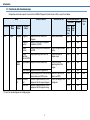


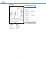
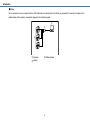
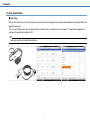
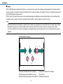
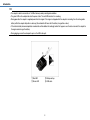
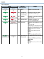
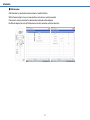
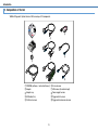
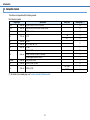

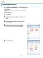
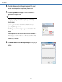

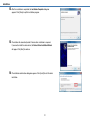


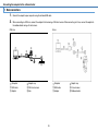
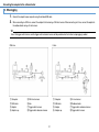
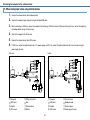
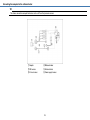
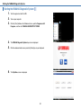
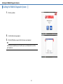
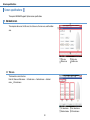
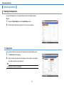

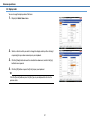
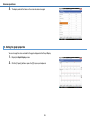
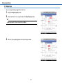
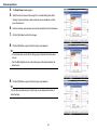
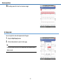

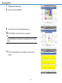
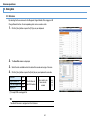
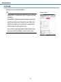
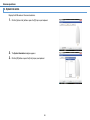
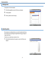
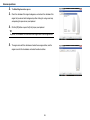

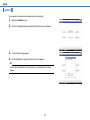
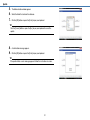
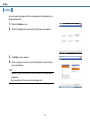
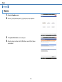
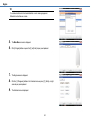
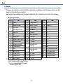
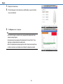

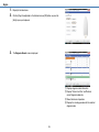
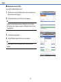
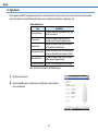
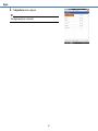
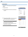
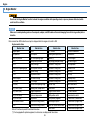
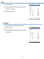
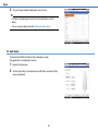
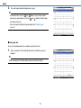

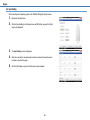

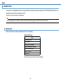
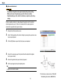
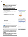
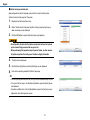
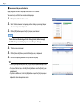
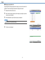
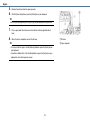

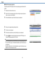
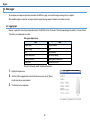
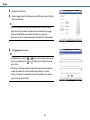
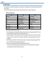
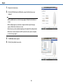


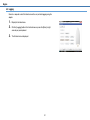
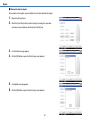
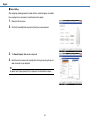
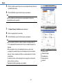
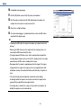
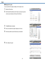

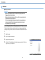
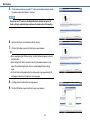
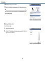
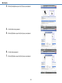

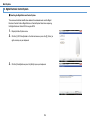
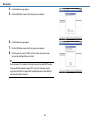
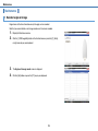
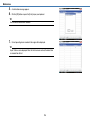
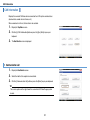
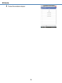
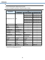


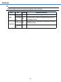

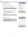


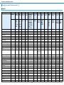


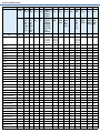
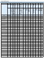
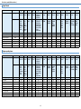
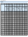
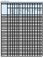
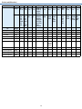
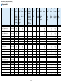
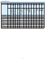
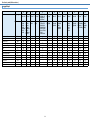
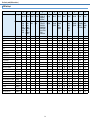
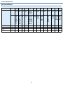
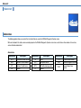


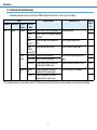
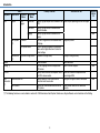
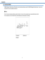
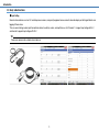
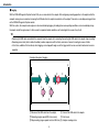
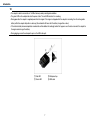
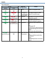


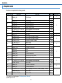


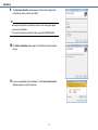

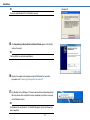
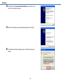
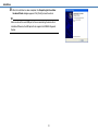
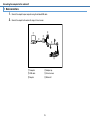
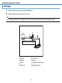
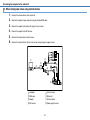
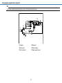
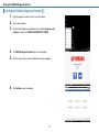
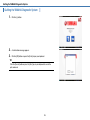
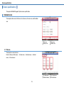


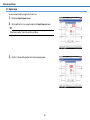
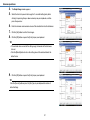
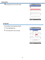
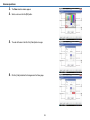
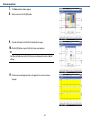
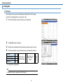

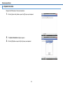
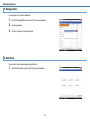

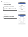


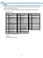
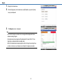
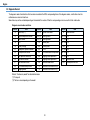
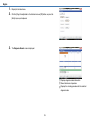
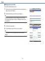
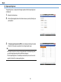
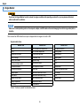
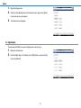
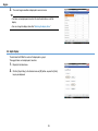

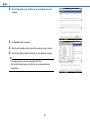
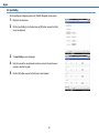
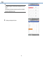
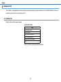

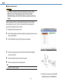

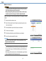

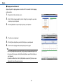


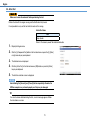
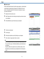
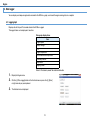
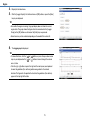
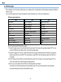
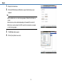
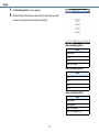
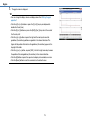
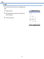
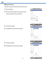

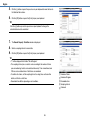
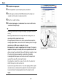

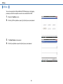
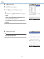

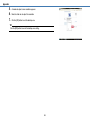
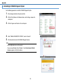
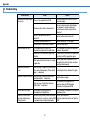
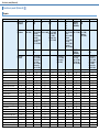
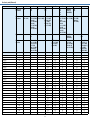
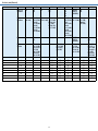
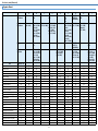
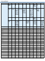
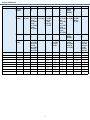
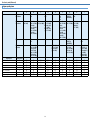
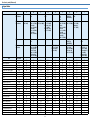
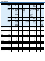

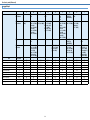


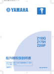


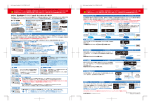

![取扱説明書[15年度CFシリーズ] (2.15 MB/PDF)](http://vs1.manualzilla.com/store/data/006670523_3-e93997b70c35e79f9d00d75a6ca8527d-150x150.png)