1
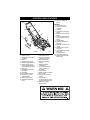
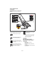
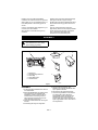
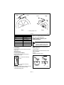
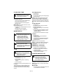
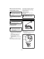
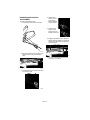
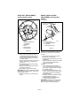
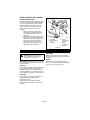
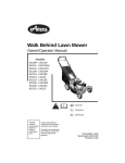
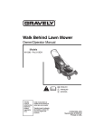
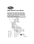
Walk Behind Lawn Mower Owner/Operator Manual Models 911086 - LM21 911087 - LM21S ENGLISH FRANÇAIS ESPAÑOL Transfer model & serial number label from product registration here. Coller l’autocollant du modèle et du numéro de série dans cet encadré. Transferir aquí la etiqueta del modelo y número de serie del registro del producto. 01198200A 2/04 Supersedes 01198200 Printed in USA CONTROLS AND FEATURES 13. Trous de réglage du guidon 11 1 10 9 12 7 2 8 6 13 6 5 4 3 Figure 1 ENGLISH 1. Engine Control 2. Speed Control Rod (Selfpropelled) 3. Primer 4. Side Discharge Cover 5. Side Discharge Deflector 6. Cutting Height Levers (2 Rear Wheel Adjusters, 2 Front Wheel Adjusters) 7. Rear Door 8. Adjustable and Folding Handlebars 9. Grass Bag 10. Recoil Starter Handle 11. Wheel Drive Control (Self-Propelled) 12. Mulchmaster™ Plug 13. Handlebar Adjustment Holes OM1410 FRANÇAIS 1. Commande moteur 2. Tige de command de vitesse (auto-tracté) 3. Poire d’amorçage 4. Plaque d’évacuation latérale 5. Déflecteur latéral d’évacuation 6. Leviers de hauteur de coupe (réglage par les roues) 7. Trappe arrière 8. Guidon réglable et pliable 9. Sac à herbe 10. Poignée du démarreur manuel 11. Commande de l’entraînement des roues (tondeuses autotractées) 12. Déflecteur à paillis Mulchmaster™ 3 ESPAÑOL 1. Control del motor 2. Varilla de control de velocidad 3. Cebador 4. Cubierta de la descarga lateral 5. Deflector de la descarga lateral 6. Palancas de la altura de corte (ajustadores de la rueda) 7. Puerta trasera 8. Manillares ajustables y plegables 9. Bolsa de recolección del césped 10. Manilla de arranque de retroceso 11. Control de la transmisión de la rueda (autopropulsión) 12. Tapón Mulchmaster™ 13. Agujeros para el ajuste del manillar TABLE OF CONTENTS Controls and Features . . . . . . . . . . . . . 3 Storage . . . . . . . . . . . . . . . . . . . . . . . . . 18 Safety . . . . . . . . . . . . . . . . . . . . . . . . . . . 5 Troubleshooting . . . . . . . . . . . . . . . . . 19 Assembly . . . . . . . . . . . . . . . . . . . . . . . . 9 Service Parts . . . . . . . . . . . . . . . . . . . . 20 Operation . . . . . . . . . . . . . . . . . . . . . . . 10 Accessories . . . . . . . . . . . . . . . . . . . . . 20 Maintenance . . . . . . . . . . . . . . . . . . . . 13 Specifications . . . . . . . . . . . . . . . . . . . 21 Service and Adjustments . . . . . . . . . . 15 Warranty . . . . . . . . . . . . . . . . . . . . . . . . 22 INTRODUCTION THE MANUAL PRODUCT REGISTRATION Before using the unit, carefully and completely read your manuals. The contents will give you an understanding of safety instructions and controls during normal operation and maintenance. All reference to left, right, front, or rear are given from the operator’s position, facing the direction of forward travel. The Ariens dealer must register the product at the time of purchase. Registering the product will help the company process warranty claims or contact you with the latest service information. All claims meeting requirements during the limited warranty period will be honored, whether or not the product registration card is returned. Keep a proof of purchase if you do not register your unit. Customer Note: If the Dealer does not register your product, please fill out, sign and return the product registration card to Ariens or go to www.ariens.com on the internet. SERVICE AND REPLACEMENT PARTS When ordering replacement parts or making service inquiries, know the Model and Serial numbers of your unit and engine. Numbers are located on the product registration form in the unit literature package. They are also printed on a serial number label, located on the frame of your unit (Figure 2). Serial Number Label Figure 2 UNAUTHORIZED REPLACEMENT PARTS Use only Ariens replacement parts. Replacing any part on this vehicle with anything other than an Ariens authorized replacement part may adversely affect the performance, durability, or safety of this unit and may void the warranty. Ariens disclaims liability for any claims or damages, whether warranty, property damage, personal injury or death arising out of the use of unauthorized replacement parts. To locate your nearest Ariens Dealer, call 1-800-678-5443 or go to www.ariens.com on the internet. DEALER DELIVERY OM1210 • Record Unit Model and Serial numbers here • Record Engine Model & Serial numbers here Dealer should: 1. Check that all assembly and adjustments have been properly completed. 2. Fill out Original Purchaser Registration Card and return the card to Ariens. 3. Explain Ariens Limited Warranty Policy. 4. Explain recommended lubrication and maintenance. Advise customer on adjustments. Remind customer to change oil in 4 cycle engine crankcase after first two (2) hours of operation. GB - 4 5. Instruct customer on controls and operation of unit. Discuss and emphasize the Safety Rules. Give customer Owner/Operator, Parts, and Engine manuals. Advise customer to thoroughly read and understand them. DISCLAIMER Ariens reserves the right to discontinue, make changes to, and add improvements upon its products at any time without public notice or obligation.The descriptions and specifications contained in this manual were in effect at printing. Equipment described within this manual may be optional. Some illustrations may not apply to your unit. SAFETY WARNING: POTENTIALLY HAZARDOUS SITUATION! If not avoided, COULD RESULT in death or serious injury. WARNING: This cutting machine is capable of amputating hands and feet and throwing objects. Failure to observe the safety instructions in the manuals and on decals could result in serious injury or death. Slopes are a major factor related to slip and fall accidents. Operation on all slopes requires extra caution. Tragic accidents can occur if the operator is not alert to the presence of children. Never assume that children will remain where you last saw them. Gasoline is extremely flammable and the vapors are explosive, handle with care. Stop unit and engine and allow moving parts to stop before leaving operator’s position. CAUTION: POTENTIALLY HAZARDOUS SITUATION! If not avoided, MAY RESULT in minor or moderate injury. It may also be used to alert against unsafe practices. NOTATIONS NOTE: General reference information for proper operation and maintenance practices. IMPORTANT: Specific procedures or information required to prevent damage to unit or attachment. PRACTICES AND LAWS SAFETY ALERTS Look for these symbols to point out important safety precautions. They mean: Attention! Personal Safety Is Involved! Become Alert! Obey The Message! Practice usual and customary safe working precautions, for the benefit of yourself and others. Understand and follow all safety messages. Be alert to unsafe conditions and the possibility of minor, moderate, or serious injury or death. Learn applicable rules and laws in your area. REQUIRED OPERATOR TRAINING Original purchaser of this unit was instructed by the seller on safe and proper operation. If anyone other than the original purchaser will use the unit, ALWAYS provide this manual and any needed safety training before operation. The safety alert symbols above and signal words below are used on decals and in this manual. Read and understand all safety messages. DANGER: IMMINENTLY HAZARDOUS SITUATION! If not avoided, WILL RESULT in death or serious injury. GB - 5 SAFETY DECALS AND LOCATIONS ALWAYS replace missing or damaged safety decals. Refer to Figure 3 for safety decal locations. CAUTION PRECAUCION ATTENTION Leer el manual del operador. Mantenga la unidad alejada de los niños u otras personas cuando esté en funcionamiento. Nunca dirija la descarga hacia otras personas, a que los objetos lanzados pueden provocar lesiones. No poner en funcionamiento la máquina a menos que las guardas estén en posición de funcionamiento o la embolsadora entera esté conectada. Mantenga artefactos de seguridad (defensas, protectores, interruptores, etc.) en su lugar y trabajando. Transversa pendientes, no subir ni bajar. Mire hacia abajo y detras antes y durante retroceso. 07742400B 00 83 08 08 Figure 3 OM1420 1. DANGER Keep safety devices (guards, shields, switches, etc.) in place and working. TO AVOID SERIOUS INJURY OR DEATH Read the operator’s manual. OL3030 OL1801 Keep children and others away from unit while operating. • Go across slopes, not up and down. • Look down and behind before and while moving backward. 2. DANGER OL4370 Never direct discharge toward other people. Thrown objects can cause injury. KEEP HANDS AND FEET AWAY Do not operate mower unless guards are in operating position or bagger is attached. 3. CAUTION! • OL0910 Do not operate mower unless guards are in operating position or entire bagger is attached. OL4540 GB - 6 • • Bag is subject to wear and deterioration. Check bag frequently, replace when necessary. Use original bag to comply with safety specifications. SAFETY RULES If unit is to be used by someone other than original purchaser; loaned, rented or sold, ALWAYS provide this manual and any needed safety training before operation. Read, understand and follow all safety practices in Owner/Operator Manual before beginning assembly. Failure to follow instructions could result in personal injury and/or damage to unit. ALWAYS disconnect wire from spark plug before assembly. Unintentional engine start up can cause death or serious injury. Complete a walk around inspection of unit and work area to understand: • work area • your unit • all safety decals. Clear work area of stones, sticks, wire and foreign objects which might be picked up and thrown. Tall grass can hide obstacles. Know the work area. Stay alert for holes, rocks, rough terrain and hidden hazards. Keep away from drop-offs, ditches, or embankments that could cause operator to lose footing or control of unit. ALWAYS be aware of traffic when operating along streets or curbs. Keep work area clear of all persons, children and pets. Keep children out of the work area and under the watchful care of a responsible adult. ALWAYS operate unit when there is good visibility and light. DO NOT mow wet grass. ALWAYS be sure of your footing. Keep a firm hold on handlebar. Walk, NEVER run. Engine/blade control feature on mower stops engine and blade within 3 seconds whenever operator releases handlebar. Check this feature frequently. If feature fails to operate, disconnect spark plug wire and adjust or have it repaired before using unit. Only trained adults may operate unit. Training includes actual operation. NEVER operate after or during the use of medication, drugs or alcohol. Unit requires complete and unimpaired attention. NEVER allow children to use mower. ALWAYS keep hands and feet away from rotating parts. Rotating parts can cut off body parts. ALWAYS keep hands away from pinch points. Fumes from engine exhaust can cause death or serious injury. DO NOT run engine in an enclosed area. ALWAYS protect eyes, face, and body with adequate safety gear and protective clothes. Wear sturdy footwear, gloves and safety goggles or safety glasses with side shields while operating mower. NEVER operate mower barefoot or when wearing open sandals or canvas shoes. NEVER wear loose clothes, long hair or jewelry that may get caught in rotating parts. ALWAYS stand clear of discharge when operating unit. NEVER direct discharge toward bystanders. Operator is responsible for bystander safety. DO NOT touch hot parts. Allow parts to cool. Keep safety devices or guards in place and functioning properly. NEVER modify or remove safety devices. Read, understand, and follow all instructions in the manual and on the machine before starting. Understand: • How to operate all controls • The functions of all controls • How to STOP in an emergency. DO NOT attempt to start your engine until you know what the controls do and how they work. DO NOT tilt mower when starting it. Keep feet away when starting engine. DO NOT start the engine or operate mower without side discharge cover or side discharge deflector installed. Take all possible precautions when leaving unit unattended. ALWAYS shut off engine and disconnect spark plug wire to prevent accidental starting or unauthorized use. Stop engine if anyone enters the work area. NEVER attempt to make any adjustments to unit while engine is running (except where specifically recommended). Stop engine and wait for all moving parts to stop before servicing. DO NOT make cutting height wheel adjustments while the engine is running. If you strike an object, or if equipment vibrates abnormally, stop engine at once, wait for moving parts to stop and disconnect wire from spark plug. Repair any damage before restarting unit. Keep rear door closed when engine is running unless the grass bag is in place. GB - 7 Stop engine before removing and emptying grass bag. When mulching or bagging, ALWAYS install discharge cover. When side discharging, ALWAYS install side discharge deflector. ALWAYS shut off engine, allow blade to stop and disconnect spark plug wire before clearing clogs or cleaning unit. Check grass bag for wear, damage, and/or deterioration. Replace only with Ariens original equipment replacement parts for safety. To reduce fire hazard and overheating, keep equipment free of grass, leaves, debris or excessive lubricants. Use extra care when approaching blind corners, shrubs, trees, or other objects which may obscure vision. DO NOT mow at too fast a rate. DO NOT change engine governor setting or over-speed the engine. Do not operate mower on gravel or loose material such as sand. Stop mower when crossing drives, walks, or roads to prevent damage or injury from thrown objects. DO NOT pull mower backwards unless absolutely necessary. Look down and back, especially for small children, before and while moving backwards. On self-propelled models, releasing wheel drive control must stop mower’s forward movement. If this feature fails to operate, disconnect spark plug wire and repair before using unit. On self-propelled models, wheel drive must be disengaged when starting engine. DO NOT operate on steep slopes. NEVER leave unit unattended on a slope. Chock wheels if parking on a slope. Mow across the face of slopes, never up and down. Be especially cautious when changing direction on slopes. This product is equipped with an internal combustion engine. DO NOT use on or near any unimproved, forest or brush covered land unless the exhaust system is equipped with a spark arrestor meeting applicable local, state or federal laws. A spark arrestor, if used, must be maintained in effective working order by the operator. See your Ariens Dealer or engine manufacturer’s service center. Fuel is highly flammable and its vapors can explode. ONLY use approved fuel containers. • NO Smoking! • NO Sparks! NO Flames! Allow engine to cool before filling fuel tank. Never fill containers inside a vehicle or on a truck or trailer bed with a plastic liner. Always place containers on the ground away from your vehicle before filling. When practical, remove gas-powered equipment from the truck or trailer and refuel it on the ground. If this is not possible, then refuel such equipment on a trailer with a portable container, rather than from a gasoline dispenser nozzle. Keep the nozzle in contact with the rim of the fuel tank or container opening at all times until fueling is complete. Do not use a nozzle lockopen device. Check fuel supply before starting engine. DO NOT fill gasoline tank indoors, when engine is running, or while engine is hot. Allow engine to cool several minutes before removing fuel cap. DO NOT overfill. Allow about 1/4" (6 mm) of tank space for fuel expansion. Replace gasoline tank cap securely and clean any spilled fuel before starting engine. If fuel is spilled on clothing, change clothing immediately. NEVER store fuel inside where there is an open flame, such as a water heater. ALWAYS drain fuel outdoors away from ignition sources. ALWAYS shut off engine when transporting unit on a truck or trailer. Avoid Electric Shock. DO NOT disconnect wire from spark plug while engine is running. Accidental engine start up can cause death or serious injury. Except where specifically recommended, ALWAYS stop engine, wait for moving parts to stop, allow parts to cool and disconnect spark plug wire before inspecting, servicing, adjusting or repairing unit. Keep mower free of grass, leaves, or other debris build-up. Keep equipment in good condition. Maintain or replace safety and instruction labels, as necessary. Follow engine manufacturer’s safety instruction when servicing engine. Check all hardware at regular intervals, especially blade attachment bolts. Keep all hardware properly tightened. Before tipping unit, remove fuel. Ensure all wheel blocks, jack stands and tie downs will support unit during maintenance. GB - 8 • • Replace worn-out mufflers immediately. Continued use could result in fire or explosion. Sharp edges can cut or amputate fingers or a hand. Wrap blade or wear sturdy gloves to service. Use only replacement parts designed for your unit. See your Ariens Dealer. Allow engine to cool before storing in any enclosure. ALWAYS clean unit before extended storage. See engine manual for proper storage. DO NOT store unit inside a building with fuel in the fuel tank where any ignition sources are present. Use only accessories which have been approved by Ariens and are properly installed. Check attachments frequently and replace worn or damaged components with manufacturer’s recommended parts. ASSEMBLY CAUTION: AAVOID INJURY. Read and understand the entire Safety section before proceeding. CARTON CONTENTS 1 2 3 OM0340 5 OM0320 OM1222 OM0350 1. 2. 3. 4. 5. Mower Unit Side Discharge Deflector Grass Bag Grass Bag Frame Literature Pack 4 OM0330 Figure 4 ASSEMBLY 1. Unfold and adjust handlebar. See Service and Adjustments. 2. Self-Propelled Models: The speed control rod is shipped on the handlebar with hardware in position. Remove hair pin, insert bent end of rod through hole in swivel of speed control bell crank, and retain with hair pin (Figure 5). 3. Fill engine crankcase with oil. See engine manual. 4. Assemble grass bag onto bag frame. GB - 9 5. Set-up mower for bagging, side discharge or mulching. See Mower SetUp in Operation Section. 6. Fill fuel tank. See Operation Section. 7. Check the engine/blade control feature. Try starting the engine without the engine/blade control held against the handlebar. Engine must not start. If engine starts, stop engine and adjust or repair engine/blade control. See Service and Adjustments. 1 3 2 1. Speed Control Rod 2. Hair Pin 3. Speed Control Bell Crank Figure 5 OM0300 OPERATION CONTROLS AND FEATURES Handlebar See Figure 1 for locations. Adjust handlebar to a safe and comfortable height. Refer to Service and Adjustments for instructions. WARNING: Improper operation can lead to injury. Learn what the controls do and how they work. Thoroughly read and understand entire Operator Manual. Recoil Starter Handle When pulled, handle will turn engine over. CUTTING HEIGHT ADJUSTMENT DANGER: Avoid injury from rotating blade. ALWAYS shut off engine before adjusting cutting height. CAUTION: AVOID INJURY. Read and understand the entire Safety section before proceeding. Engine/Blade Control CAUTION: On self-propelled models, both rear wheels must be set at same height or traction drive may not work properly. CAUTION: Check function of Engine/Blade Control regularly. Improper function of control could cause injury. Standard Models The engine/blade control must be held against the handlebar to start the engine and blade. Releasing the control during operation stops the engine and blade. STOP To change cutting height, move cutting height levers one notch at a time on each wheel to set desired height (Figure 6). NOTE: Each wheel on mower must be set at the same height for a level cut. START and RUN OM1230 GB - 10 High Low Low High 1 1 Rear 1. Cutting Height Lever Front Figure 6 Speed control rod should hold the desired speed. If not, adjust speed control bell crank (See Service and Adjustments). Cutting Height Settings Chart Notch Cut grass length LOW 1" (25 mm) 2 1-3/8" (35 mm) 3 1-3/4" (45 mm) 4 2-1/4" (57 mm) 5 2-3/4" (70 mm) HIGH 3-1/4" (83 mm) OM0165 WHEEL DRIVE CONTROL (selfpropelled models) CAUTION: Unit will move forward at engine start if wheel drive control is engaged. ALWAYS release wheel drive control before starting unit. OPTIONAL CONTROLS Primer Bulb Push the primer bulb in to add fuel for easier engine start. Speed Control (self-propelled models) Speed control rod changes the mower’s forward travel speeds. NOTE: Engine must be running for wheel drive to propel unit. To drive forward: Slowly squeeze and hold wheel drive control against handlebar. To stop: Release wheel drive control. High –Push lever all the way forward. Low –Pull lever all the way rearward. Start mowing slowly and use speed control rod to gradually increase speed to a safe, comfortable walking pace. OM0480 GB - 11 STOP GO OM1240 FILLING FUEL TANK Grass Bag Removal CAUTION: AVOID INJURY. Read and understand the entire Safety section before proceeding. To add fuel to fuel tank: 1. Put unit in open or well-ventilated area. 2. Stop engine and allow to cool. 3. Clean fuel cap and surrounding area. 4. Remove cap. IMPORTANT: See engine manual for correct type and grade of fuel. 5. Fill fuel tank. (See Specifications for tank capacity.) 6. Replace fuel cap and tighten. 7. ALWAYS clean any spilled fuel. 1. Shut off unit. 2. Lift rear door. 3. Use handle to lift bag off mounting flange. 4. Close rear door. NOTE: Empty grass bag and clean mower pan after each use. DO NOT allow grass clumps or a grass coating to collect inside of grass bag or mower pan. Remove grass bag from mower, wash bag with hose and allow to dry. To Side Discharge 1. Shut off unit. 2. Install Mulchmaster plug (see below). 3. Remove grass bag. 4. Remove side discharge cover and keep hardware. 5. Attach side discharge deflector to studs on mower. Make sure deflector covers discharge opening. 6. Secure with cover hardware from step 4. MOWER SET-UP CAUTION: DO NOT operate mower unless either side discharge cover or side discharge deflector is installed. Thrown objects may cause damage or injury. Never operate unit with rear door open unless grass bag is in place. CAUTION: If clog or obstruction prevents grass flow, release engine/blade control and disconnect spark plug wire before attempting to clear away any clogs. To Bag CAUTION: Check grass bag frequently for wear or deterioration. Replace worn or damaged bag with Ariens original equipment replacement bag only. To Mulch 1. Shut off unit. 2. Remove grass bag and install side discharge cover. 3. Open rear door and insert Mulchmaster plug with the beveled face to the left. 4. Close rear door. NOTE: Rear door must close flush. NOTE: For maximum mulching performance, install the Mulchmaster Mulching kit. See Accessories. EMERGENCY STOPPING To stop the mower in an emergency: 1. Release the engine/blade control. 2. Release the wheel drive control (selfpropelled models). 3. Allow all moving parts to stop before leaving operator’s position. STARTING AND SHUT OFF 1. Shut off unit. 2. Install side discharge cover. 3. Lift rear door. 4. Hook grass bag frame on mounting flange. 5. Lower rear door. If necessary, lift rear of grass bag frame to lock in position. There should be no openings between bag and mounting surface after installing bag. If necessary clear debris from bag mounting surface. WARNING: Improper operation can lead to injury. Learn what the controls do and how they work. Thoroughly read and understand entire Operator Manual. See Figure 1 for all Controls and Features. NOTE: Start engine on a level surface that is free of debris. Manual Start GB - 12 1. Check each item under Before Each Use in the Maintenance Schedule. 2. For engines with a primer, push primer bulb 2 or 3 times for a cold engine. NOTE: It is unnecessary to prime or choke a warm engine. 3. With engine/blade control held against the handlebar, grasp starter handle and pull rope slowly until it pulls harder. This is the compression stroke. Let rope rewind slowly. 4. Pull rope with rapid continuous full arm stroke to start engine. Allow rope to rewind slowly. IMPORTANT: DO NOT let starter handle snap against bracket. 5. Repeat steps 4 and 5 until engine starts. (If engine does not start, refer to Troubleshooting.) Shut Off 2. Release engine/blade control. Mowing Tips Cut grass when it is dry. Keep mower blades sharp. Do not set cutting height too low. For tall grass, mow twice. Do not mow too fast. Discharge clippings into areas already cut. Vary cutting pattern with each mowing. NOTE: To prevent dirt and grass from collecting on mower pan, avoid operating over bare ground with only patches of grass. Mulching Tips For best mulching performance, cut no more than 1 inch (2.54 cm) of grass per cutting. 1. Release wheel drive control and allow unit to stop completely (self-propelled models). MAINTENANCE MAINTENANCE SCHEDULE CAUTION: AVOID INJURY. Read and understand the entire Safety section before proceeding. Service Performed Ariens Dealers will provide any service, parts or adjustments which may be required to keep your unit operating at peak efficiency. Should engine require service, contact an Ariens dealer or an authorized engine manufacturer's service center. MAINTENANCE SCHEDULE NOTE: Some working conditions (heavy loads, high ambient temperatures, dusty conditions, or airborne debris) may require more frequent service. See engine manual for further maintenance and troubleshooting information. Check Engine/Blade Control Check Wheel Drive Control Check Grass Bag Clean Unit Check Engine Oil Check Mower Blade Check Drive Belt Check Fasteners Check Air Cleaner Change Engine Oil General Lubrication Check Spark Plug Check Engine Cooling Check Muffler * Before Each Use • 25 100 • • • • • • • • • *• • • • After first 5 Hours of operation CHECK ENGINE/BLADE CONTROL The engine and blade must stop within 3 seconds after releasing the control. If the engine and blade continue to run, adjust or repair control immediately. See Service and Adjustments. GB - 13 CHECK WHEEL DRIVE CONTROL (self-propelled models) 2 3 The unit must stop quickly and completely when the control is released. Adjust or repair if necessary. See Service and Adjustments. 1 CHECK GRASS BAG Check grass bag frequently for wear or deterioration. Replace worn or damaged bag with Ariens original equipment replacement bag only. 1 OM0235 Replace CLEAN UNIT Before each use clean unit, muffler and engine surfaces of debris, oil or fuel spills to ensure proper cooling and prevent fires. 4 CHECK ENGINE OIL OM0246 IMPORTANT: Proper oil level must be maintained at all times or engine damage will result. Check the level of the engine crankcase oil before each use. Make sure engine is level when checking oil. See engine manual for instructions. 1. 2. 3. 4. Cutting Edge Square Corner Air Lift Air Lift Erosion Figure 7 CHECK MOWER BLADE CHECK DRIVE BELT See Figure 7. Check blade mounting: blade must be secure and bolt torqued to 37.5 - 50 ft. lbs. (bolt should fully compress lock washer). Check blade for nicks and dull cutting edges. Sharpen if necessary. Check blade for rounded or broken ends, thinned metal or other damage. Replace if necessary. NOTE: Blades should be sharpened and balanced professionally. Contact your Ariens Dealer. To remove blade: 1. Block blade to prevent rotation. 2. Remove bolt, lock washer, flat washer and blade from shaft. To install blade: 1. Replace blade, flat washer, lock washer and bolt on shaft. 2. Torque bolt to 37.5 - 50 ft. lbs. (bolt should fully compress lock washer). Check drive belt and replace if worn or damaged. See Service and Adjustments. CHECK FASTENERS Check all fasteners for proper tightness. Pay special attention to blade hardware and all guards, shields and safety devices. CHECK AIR CLEANER See engine manual for specific information. CHANGE ENGINE OIL IMPORTANT: Change engine crankcase oil after first five (5) hours of operation. Then change oil after every 25 hours of operation. Refer to engine manual for instructions and proper oil type. IMPORTANT: Proper oil level must be maintained at all times or engine damage will result. DO NOT overfill. Be sure engine is level when adding oil. GENERAL LUBRICATION Mower Mower requires no lubrication. CHECK SPARK PLUG Spark plug should be replaced every 100 hours of operation or each year. GB - 14 NOTE: Loose spark plug wire terminals can cause sparking. Replace terminal if damaged. CHECK ENGINE COOLING WARNING: HOT SURFACES can cause death or serious injury. DO NOT TOUCH parts which are hot from operation. ALWAYS allow parts to cool. Every 100 hours of operation or yearly (more often if conditions require) remove blower housing and clean cooling fins. See engine manual for instructions. CHECK MUFFLER Check muffler for debris, cracks, wear, or other damage. CAUTION: Replace worn out mufflers immediately. Continued use could result in fire or explosion. To prevent overheating, air must circulate freely around the cooling fins, cylinder head and block. SERVICE AND ADJUSTMENTS CAUTION: AVOID INJURY. Read and understand the entire Safety section before proceeding. SERVICE POSITION Put unit into service position for easy access to underneath the deck. CAUTION: Avoid fuel spills. Follow steps below to help prevent fuel spills. If fuel leaks into air cleaner, replace air cleaner. ALWAYS clean up any spilled fuel. Figure 8 1. Place unit on a flat, level surface. 2. Remove fuel cap, place a piece of plastic bag over the opening and tighten cap securely. 3. Adjust handlebar forward to service position and secure (Figure 8). 4. Tip unit onto left side, opposite the discharge opening. Make sure unit is secure and will not tip over. OM0217 HANDLEBAR HEIGHT To adjust (Figure 9): 1. Place a hole at the bottom of the braces over the pins on the bracket. Pin IMPORTANT: Remove plastic from fuel cap after unit is upright and service is complete. Hole Figure 9 GB - 15 OM0275 ENGINE/BLADE CONTROL ADJUSTMENT 4. Tighten lower cable nut to 1/8" (3mm) below bracket. Release z-bend bracket. To adjust engine/blade control: 1. Loosen cable nuts away from bracket. 1/8 (3mm ) OM1020 5. Tighten upper cable nut until bracket is secure between cable nuts. OM1030 6. Engage engine/blade control. Measure distance between middle of z-bend and cable bracket. Measurement should be as shown below. 1.325"-1.788" (3.4cm - 4.5cm) OM1010 2. Squeeze z-bend bracket at engine end of cable toward front of unit and hold in place. Quantum OM1051 7. If correct measurement cannot be set, contact your local dealer. Quantum OM1040 3. Pull cable down from bracket until there is no slack in cable. No slack OM1061 GB - 16 DRIVE BELT REPLACEMENT (self-propelled models) WHEEL DRIVE CONTROL ADJUSTMENT (self-propelled models) See Figure 11. 2 6 1-1/2" to 2" (3.8 to 5cm) 1 2 4 3 4 3 5 1 1. Blade 2. Bolt, Lock Washer & Flat Washer 3. Drive Belt 4. Idler 5. Drive Sheave 6. Engine Pulley Figure 10 1. 2. 3. 4. Traction Cable Handlebar Indentation Cable Nuts Wheel Drive Control OM0290 Figure 11 OM1250 To remove drive belt: 1. Set the right rear wheel to its lowest cutting height, and the left rear wheel to the third cutting height. This position provides clearance between friction disc and drive sheave. 2. Remove belt from the idler, then the drive sheave, and finally, the engine pulley (Figure 10). 3. Pull belt through opening under mower pan and over blade. 4. Make sure the idler pulley turns and the idler arm moves freely. 5. Reinstall drive belt in reverse order. IMPORTANT: Be sure the belt seats in sheave and pulley grooves with the idler touching the back (flat) side of belt. 6. Adjust rear wheels to the same cutting height. The wheel drive must start to engage when wheel drive control is between 1-1/2” and 2” (3.8 and 5 cm) away from the handlebar. To check: 1. With engine off, select a slow speed. 2. Slowly pull unit backwards. 3. Slowly squeeze wheel drive control until wheels stop. 4. Measure the distance between the wheel drive control and handlebar at the handlebar indentation. To adjust: 1. If the measurement is more than 2” (5cm), loosen the lower cable nut and then tighten the upper cable nut against the adjuster bracket. 2. If the measurement is less than 1-1/2” (3.8cm), loosen the upper cable nut and then tighten the lower nut against the adjuster bracket. 3. Recheck measurement with the slowest and fastest speeds selected. 4. Repeat adjustment until wheel drive control is properly adjusted. IMPORTANT: If there is not enough thread length for proper adjustment, contact your Dealer for repairs before operating unit. GB - 17 SPEED CONTROL BELL CRANK (self-propelled units) 1 The speed control bell crank holds the speed control rod in position after a speed has been set. The spring washers may become loose with normal wear. If the speed control rod does not stay firmly in position, adjust the speed control bell crank. See Figure 12. To adjust: 1. Remove cover, fully compress the helical spring lock washers with lock nut and then back lock nut off, one quarter turn. 2. If the speed control rod is still too loose, tighten lock nut by small increments until it holds its position. Tightening the lock nut too much will not allow the speed control rod to move at all. 3. Align notch in left hand side of cover with bolt and secure with knob. 2 4 3 5 6 OM0300 1. Lock Nut 2. Helical Spring Lock Washers 3. Speed Control Bell Crank 4. Speed Control Rod 5. Hair Pin Figure 12 STORAGE Grass Bag CAUTION: AVOID INJURY. Read and understand the entire Safety section before proceeding. Wash out grass bag and allow to dry before storage. Grass bag may be stored in position on mower. Engine IMPORTANT: NEVER spray unit with water or store unit outdoors. Store mower in a cool, dry, protected location. Cleaning When storing unit for extended periods of time, remove all fuel from tank and carburetor (run dry). Refer to engine manual. Clean unit thoroughly. Brush off dirt and debris from all surfaces. Touch-up all scratched surfaces to prevent rust. Matching touch-up paint is available from your Ariens Dealer. Do not use abrasives, solvents, or harsh cleaners. Inspection Inspect mower and repair or replace worn or damaged parts to avoid delays when beginning use again. Regularly check all hardware and keep fasteners tight. Know unit is in safe working condition. GB - 18 TROUBLESHOOTING PROBLEM PROBABLE CAUSE Engine will not start 1. Fuel tank empty or low. 2. Spark plug wire loose or off. 3. Engine/Blade control cable detached, broken, or not adjusted properly. 1. Check fuel level. Fill tank if necessary. 2. Check connection. 3. Check cable. Adjust, repair or replace as necessary. Engine is difficult to restart 1. Mower clogged with grass. 1. Clear clippings from under mower. (Allow the mower to clear clippings before shutting off engine.) Cut is poor 1. Worn blade. 2. Too much grass is being removed per cutting. 3. Grass is too wet. 4. Mowing speed is too fast. 1. Check blade (See Maintenance). 2. Raise cutting height. 3. Allow grass to dry. 4. Mow slower. Grass does not disperse evenly 1. Too much grass is being removed per cutting. 2. Grass is too wet. 3. Mowing speed is too fast. 1. Raise cutting height. 2. Allow grass to dry. 3. Mow slower. Mower does not bag clippings 1. Grass bag is overfilled. 2. Mulching plug is installed. 1. Empty grass bag and do not allow it to overfill. 2. Remove mulching plug. Wheel drive does not engage (SelfPropelled models). 1. Wheel drive control not engaged. 2. Drive belt out of position. 3. Drive belt worn or damaged. 4. Rear wheels in different cutting heights. 5. Idler spring detached. 6. Wheel drive control cable detached or broken. 7. Friction disc not adjusted properly or damaged. 8. Bearings damaged. 9. Debris in gear set. 1. Engage wheel drive control. 2. Check drive belt. Adjust as necessary (See Service and Adjustments). 3. Replace belt (See Service and Adjustments). 4. Adjust rear wheels to same cutting height (See Operation). 5. Attach idler spring to notch on idler arm. Contact your Dealer. 6. Check wheel drive control cable. Adjust or replace as needed. See Service and Adjustments. 7. Contact your Dealer. 8. Contact your Dealer. 9. Contact your Dealer. GB - 19 CORRECTION SERVICE PARTS Always use genuine Ariens parts to keep your mower running like new. Mower Model 911086 ACCESSORIES See your authorized Ariens dealer to add these optional accessories. 911087 71102400 Dethatcher Air Filter 21535600 71103700 Leaf Shredder Fuel Filter 21533900 71103000 Grass Bag Blade 01137000 71103200 Rear Discharge Chute 71103500 Mulchmaster Mulching Kit 71104100 Swivel Wheel Kit GB - 20 SPECIFICATIONS Model Number Description Length - in (cm) Height - in (cm) Width - in (cm) Actual Weight - lbs (kg) Cutting Width Cutting Height - in. (cm) 911086 LM21 61.5 (156) 38 (96,5) 23 (58,4) 77 (35) 93 (42,27) 21 (53,3) 6 Positions: 1.00 - 3.25 (2,5 - 8,3) Briggs & Stratton Quantum 3.6 (2,6) Engine, 4 cycle Engine Power Max - HP (kw) Max Rotation Speed of Cutting Edge - RPM (min-1) Governed RPM 3100 3000 +/- 100 12 (197) Displacement Cu. In. (cc) Cylinder Bore Engine Oil Type Crank Case Capacity - Oz. (Liter) Oil System Spark Plug Gap - in (mm) Fuel Type Fuel Tank Capacity - qt (Liter) Primer Bulb Air Cleaner Starting Differential Variable Speeds - MPH (km/hr) Mower Deck Adjustable Handlebar Front Wheel Dia - in (cm) Rear Wheel Dia - in (cm) 911087 LM21S Aluminum SAE 30 20 (0,59) Splash 0.020 (0,51) Unleaded 1.6 (1,5) Standard Paper Element Recoil N/A Standard N/A 0-4 (0-6,4) 14 Gauge - Stamped Steel Four Position 7.0 (17,8) 7.5 (19,1) 10.0 (25,4) 10.5 (26,7) GB - 21 GB - 22 Ariens Company 655 West Ryan Street P.O. Box 157 Brillion, WI 54110-0157 920-756-2141 Fax 920-756-2407 www.ariens.com