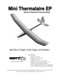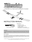
1
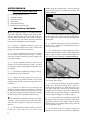
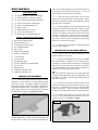
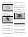
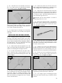
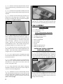
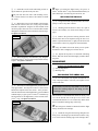
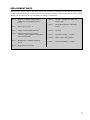
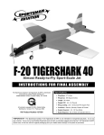
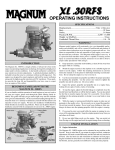
INSTRUCTIONS FOR FINAL ASSEMBLY Thank you for choosing the Wattage Omega 636 EP Glider as your next airplane. Whether you have built and flown other electric airplanes in the past, or if this is your first, you will appreciate the high quality, easy final assembly and excellent flight characteristics of the Omega 636. The Omega 636 is a lightweight 72" T-tail electric glider that is ideal for thermal soaring and general sport flying. The Omega 636 features a white gel-coated fiberglass fuselage, built-up fully-sheeted plug-in wing panels, and a removable sheet balsa stabilizer. The wing panels and stabilizer are covered with real iron-on covering material. The wings are removable for easy transport and feature dual aileron servos for crisp, solid control. The Omega 636 comes with a preinstalled electric motor, a folding propeller assembly and a spinner. With a seven cell flight battery and 30 amp speed control, the Omega 636 climbs with authority and flies with ease. When you open the box, you will notice that you won't have much left to do or to purchase to finish your new airplane. Most of the airplane has already been expertly preassembled for you. Simply install your radio system, bolt the stabilizer and wing halves into place and go fly. It doesn't get much easier than that. We hope you enjoy your new Wattage Omega 636 EP Glider as much as we have enjoyed designing and building it for you. If you have any questions or comments, please feel free to contact us. We have included a product survey in the back of this manual. After you have finished assembling the Omega 636, please take a minute to fill it out and send it to us. We always appreciate hearing the comments and suggestions that you have. The Wattage Omega 636 EP Glider is distributed exclusively by Global Hobby Distributors 18480 Bandilier Circle, Fountain Valley, CA 92728 All contents copyright © 2001, Global Hobby Distributors Version V1.0 1/2001 1 TABLE OF CONTENTS Safety Warning ............................................................... 2 Final Assembly ............................................................. 12 Our Recommendations ................................................... 3 Installing the ESC, Receiver & Flight Battery ...... 12 Additional Items Required ............................................. 4 Applying the Decals .............................................. 13 Tools and Supplies Required ......................................... 4 Balancing ...................................................................... 13 Kit Contents.................................................................... 5 Balancing the Omega 636 ...................................... 13 A Note About Covering ................................................. 5 Control Throws ............................................................ 14 Motor Break-In............................................................... 6 If You're Using a Computer Radio ........................ 14 Breaking In the Motor ............................................. 6 Flying the Omega 636 .................................................. 14 Wing Assembly .............................................................. 7 Basics of Thermal Flying ............................................. 15 Hinging the Ailerons ................................................ 7 Glossary of Terms ........................................................ 15 Installing the Aileron Servos ................................... 7 Notes ............................................................................. 16 Installing the Servo Covers ..................................... 8 Replacement Parts ........................................................ 17 Installing the Aileron Linkage ................................. 9 Product Evaluation Sheet ............................................. 19 Wing Mounting ............................................................ 10 Joining the Wing Panels ........................................ 10 Stabilizer Installation ................................................... 10 Mounting the Stabilizer ......................................... 10 Pushrod Installation ..................................................... 11 Installing the Elevator Servo ................................. 11 Installing the Elevator Pushrod ............................. 11 To make your modeling experience totally enjoyable, we recommend that you get experienced, knowledgeable help with assembly and during your first flights. Your local hobby shop has information about flying clubs in your area whose membership includes qualified instructors. We also recommend that you contact the AMA at the address below. They will be able to help you locate a flying field in your area also. Academy of Model Aeronautics 5151 East Memorial Drive Muncie IN 47302-9252 (800) 435-9262 www.modelaircraft.org Wattage guarantees this kit to be free from defects in both material and workmanship, at the date of purchase. This does not cover any component parts damaged by use, misuse or modification. In no case shall Wattage's liability exceed the original cost of the purchased kit. In that Wattage has no control over the final assembly or material used for final assembly, no liability shall be assumed for any damage resulting from the use by the user of the final user-assembled product. By the act of using the final user-assembled product, the user accepts all resulting liability. SAFETY WARNING This R/C airplane is not a toy! If misused, it can cause serious bodily injury and/or damage to property. Fly only in open areas and preferably at a dedicated R/C flying site. We suggest having a qualified instructor carefully inspect your airplane before its first flight. Please carefully read and follow all instructions included with this airplane, your radio control system and electronic speed control. 2 This instruction manual is designed to guide you through the entire final assembly process of your new Wattage Omega 636 EP Glider in the least amount of time possible. Along the way you'll learn how to properly assemble your new airplane and also learn many tips that will help you in the future. We have listed some of our recommendations below. Please read through them before going any further. ✔ Please read through each step before starting assembly. You should find the layout very complete and simple. Our goal is to guide you through assembly without any of the headaches and hassles you might expect. ✔ There are check boxes next to each step. After you complete a step, check off the box. This will help prevent you from losing your place. ✔ Cover your work table with brown paper or a soft cloth, both to protect the table and to protect the individual parts. ✔ Keep a couple of small bowls or jars handy to put the small parts in after you open the accessory bags. ✔ We have included a glossary of terms beginning on page # 15. Check it out if you come across a term that is unfamiliar to you. ✔ We're all excited to get a new airplane in the air, but take your time. This will ensure you build a straight, strong and great flying airplane. ☛ ✔ If you come across this symbol , it means that this is an important point or an assembly hint. If you should find a part missing or damaged, or have any questions about assembly, please contact us at the address below: Wattage Customer Care 18480 Bandilier Circle Fountain Valley CA 92728 Phone: (714) 963-0329 Fax: (714) 964-6236 E-mail: [email protected] OUR RECOMMENDATIONS The following section describes our recommendations to help you in deciding which types of accessories to purchase for your new Wattage Omega 636. We have tested all of these items with the airplane and found that these products will offer the best in performance, reliability and economy. RADIO SYSTEM The Omega 636 will require a minimum 3 channel radio control system with one standard servo and two sub-micro servos. The radio system we recommend using is the Hitec Focus 3 AM radio with 2 HS-81 Sub-Micro servos. This radio system includes two sub-micro servos, a three channel mini receiver, servo mounting hardware and a setup guide. If you purchase this radio you will also need to purchase one extra standard servo. We recommend using the Cirrus CS-71BB servo (P/N 444110). If you want to purchase a radio system that will be more upgradeable in the future, a four or more channel radio with one standard servo and two sub-micro servos and a mini or micro receiver will work well. If you decide to go this way, our recommendation would be to use the Hitec Flash 4X Glider FM Computer radio with 2 HS-81 Sub-Micro servos. This is a very good radio system that offers the capability to grow as your experience grows. If you purchase this radio you will also need to purchase one extra standard servo. We recommend using the Cirrus CS-71BB servo (P/N 444110). If you already have a standard radio system, you will need to purchase an after-market mini or micro receiver, one standard servo and two sub-micro servos. If you need to purchase these items we recommend the Hitec Micro 555 receiver (P/N 759118), one Cirrus CS-71BB servo (P/N 444110) and two Cirrus CS-21 Sub-Micro servos (P/N 444227). ☛You can use a standard size receiver with the Omega 636; however, the lighter the airplane is the better its overall performance will be. For this reason, we recommend using a mini or micro receiver to save weight. Our Recommendations Cont.8 3 ELECTRONIC SPEED CONTROL To operate the motor, we suggest using a 6 - 10 cell proportional electronic speed control (ESC) that features battery eliminator circuitry (BEC), auto-cutoff and a brake. BEC allows you to eliminate the receiver battery and uses the flight battery to control both the motor and the radio system. Eliminating the receiver battery provides a great weight savings which effectively increases performance. The auto-cutoff feature turns off the motor when the voltage in the battery drops too low to operate the radio system safely. This guarantees safe operation throughout the entire flight. The brake feature prevents damage to the motor and ESC when the propeller folds back during glide. To obtain these features, we suggest using the Wattage IC-30A ESC (P/N 128486). The IC-30A is a high frequency controller that is micro-processor controlled for linear throttle response, and features no-hassle digital setup. FLIGHT BATTERY The battery you choose should be a 7 cell (8.4Volt) 1700Mah Nickel Cadmium (NiCD) battery pack. We recommend using the Trinity RC1700 Flat Pack (P/N 841283). For more climb power but less duration, you can use the Trinity 8 cell (9.6Volt) 1500Mah NiCD Flat Pack (P/N 842005). These two battery packs were originally made for R/C car use, but they are excellent choices for larger electric airplanes like the Omega 636. BATTERY CHARGER Because of the flight battery's large capacity and because it powers both the motor and the radio system, we suggest using an Automatic Delta Peak Charger such as the Promax Activator Digital Peak Charger (P/N 885650). It is vital to the Omega 636's flying performance that the flight battery be fully peak charged every flight, so using a peak charger is very important. ADDITIONAL ITEMS REQUIRED ❑ {1} Hitec Focus 3 AM Micro Radio System ❑ {1} Cirrus Y-Harness # 444728 ❑ {1} Cirrus CS-71BB Standard Servo # 444110 ❑ {1} Trinity AA Batteries - 8 pack # 837801 ❑ {1} Wattage IC-30A ESC # 128486 ❑ {1} Promax Activator Digital Charger # 885650 ❑ {1} Trinity 7C 1700Mah Battery # 841283 ❑ {1} Dubro 3/8" Heat Shrink Material # 867903 ❑ {2} Cirrus 24" Servo Extensions # 444718 ❑ {1} Dubro Hook & Loop Material # 568906 The part numbers for the Cirrus servo, servo extensions and Y-harness shown above are compatible with Hitec and JR radio systems. These items are also available with plugs that are compatible with both Airtronics and Futaba radio systems. Please ask or see your dealer for those part numbers. TOOLS AND SUPPLIES REQUIRED ❑ Kwik Bond 5 Minute Epoxy # 887560 ❑ Straight Edge Ruler ❑ Kwik Bond Thin C/A # 887500 ❑ Builder's Triangle ❑ # 0 Phillips Head Screwdriver ❑ 220 Grit Sandpaper w/Sanding Block ❑ # 1 Phillips Head Screwdriver ❑ Pen or Pencil ❑ Excel Modeling Knife # 692801 ❑ Scissors ❑ Adjustable Wrench ❑ Masking Tape ❑ Needle Nose Pliers ❑ Rubbing Alcohol ❑ Wire Cutters ❑ Paper Towels ❑ Magnum Z-Bend Pliers # 237473 ❑ NHP Epoxy Mixing Sticks # 864204 ❑ Electric or Hand Drill ❑ NHP Epoxy Mixing Cups # 864205 ❑ 1/16" Drill Bit ❑ Trinity Break-In Drops # 840365 ❑ 5/64" Drill Bit ❑ Performance Plus Motor Spray # 340186 4 KIT CONTENTS We have organized the parts as they come out of the box for easier identification during assembly. Before you begin assembly, group the parts like we list them. This will ensure that you have all of the parts before you begin assembly and it will also help you become familiar with each part. If you find a part missing or damaged please call our Customer Service Department at 1-714-962-0329 or send us an email at [email protected] AIRFRAME ASSEMBLIES WING ASSEMBLY ❑ {1} Molded Fiberglass Fuselage w/Motor & Prop ❑ {1} Aluminum Dihedral Brace ❑ {1} Right Wing Panel w/Aileron & Hinges ❑ {1} 2mm x 20mm Steel Pin ❑ {1} Left Wing Panel w/Aileron & Hinges ❑ {2} 3mm x 22mm Machine Screws ❑ {1} Horizontal Stabilizer w/Elevator & Hinges ❑ {2} 3mm x 15mm Machine Screws CONTROL ASSEMBLIES MISCELLANEOUS ITEMS ❑ {1} Nylon Inner Pushrod Tube ❑ {2} Molded Plastic Servo Covers ❑ {2} 2mm x 300mm Threaded Pushrod Wires ❑ {8} 2mm x 6mm Wood Screws ❑ {2} 2mm x 22mm Threaded Rods ❑ {4} Hardwood Servo Mounting Blocks ❑ {2} Nylon Control Horns w/Backplates ❑ {2} 3mm x 15mm Wood Screws ❑ {4} 2mm x 12mm Machine Screws ❑ {3} 40mm Velcro® Strips ❑ {4} Metal Clevises ❑ {1} Decal Sheet Wattage carries a complete line of replacement parts for your Omega 636. Listed on page # 17 are the replacement parts that are available, along with their respective part numbers for easy ordering convenience. These replacement parts can be ordered through your local dealer or directly from Wattage by calling 1-714-964-0329. A NOTE ABOUT COVERING The covering material used on the Omega 636 is real iron-on heat shrink covering material, not cheap "shelf paper." Because of this, it is possible with heat and humidity changes that the covering on your airplane may wrinkle or sag. This trait is inherent in all types of heat shrink material. To remove the wrinkles you will need to purchase, or borrow from a fellow modeler, a heat iron. If you need to purchase one, the Global Heat Sealing Iron # 360900 is recommended. Follow these simple steps to remove the wrinkles: ❑ 1) Plug in and turn on the sealing iron to the medium temperature setting. Allow the iron to heat up for approximately 5 - 7 minutes. ❑ 2) After the iron has reached temperature, lightly apply the iron to the wrinkled section of the covering. Move the iron slowly over the wrinkled section until the covering tightens and the wrinkles disappear. You will notice that the color of the covering will darken when it is heated. When the covering cools back down, it will return to its normal color. ☛If the color layer smears from any of the seams, the temperature of the iron is too hot. Turn the temperature dial down and wait about 5 minutes for the iron to adjust to the lower temperature. You can remove any excess color streaks using a paper towel soaked with a small quantity of Acetone. 5 MOTOR BREAK-IN TOOLS AND SUPPLIES REQUIRED ❑ ❑ ❑ ❑ ❑ ❑ # 1 Phillips Head Screwdriver Adjustable Wrench Needle Nose Pliers Paper Towels Trinity Break-In Drops Performance Plus Motor Spray handles using three rubber bands. This will keep the motor secure enough for the break-in procedure. See photo # 1 below. Photo # 1 BREAKING IN THE MOTOR ☛Before beginning assembly, we recommend that you first break in the motor. Taking the time to do this now will do a couple of things. First, it will improve the performance and life of the motor and, second, it will give you a chance to test your radio system, ESC and flight battery before installing them into the airplane. ❑ 1) Using a # 1 phillips screwdriver, remove the screw that holds the spinner cone in place. Remove the spinner cone and screw and set them aside. ❑ 2) Using an adjustable wrench, remove the hex nut and washer from the propeller adapter. Carefully remove the propeller assembly by gently pulling it off the propeller adapter. ❑ 8) Turn on the transmitter and plug the flight battery into the speed control. If the motor turns on immediately, use the throttle lever on the back of the transmitter to turn off the motor. ❑ 9) With the motor turned off, test the operation of the three servos. All three servos should move when you move the control stick. ❑ 10) Carefully spray a couple of light sprays of Performance Plus Motor Spray inside the motor openings and apply a couple of drops of Trinity Break-In Drops onto each of the two motor bushings. See photo # 2 below. Photo # 2 ❑ 3) Using a # 1 phillips screwdriver, remove the two machine screws that hold the motor in place. Set them aside and remove the aluminum plate and the motor from the fuselage. ❑ 4) Lay the motor, flight battery, charger, radio system and ESC onto your work table. ❑ 5) Charge the flight battery using your peak charger, following the instructions that were provided with the charger. Install 8 AA batteries into the Focus 3 transmitter. ❑ 6) Plug the two sub-micro servo leads into the Y-Harness. Plug the Y-Harness, standard servo lead and the ESC lead into their proper slots in the receiver. Plug the red motor lead into the red lead on the ESC and plug the black motor lead into the black lead on the ESC. ❑ 11) Using a couple of paper towels, wipe off the excess motor spray and oil. ❑ 12) Slowly turn on the motor using the transmitter throttle lever. Position the throttle lever to about 1/3 throttle and let the motor run. While the motor is running, apply a light spray of motor spray inside the motor openings once every minute, followed by a small drop of Break-In Drops on each of the bushings. Do this until the battery is fully discharged (i.e., the motor stops). connectors. If your ESC does not use bullet connectors, you will need to change the connectors on the ESC at this time. ❑ 13) After the battery has discharged and the motor has stopped, spray motor spray through the motor openings until the fluid runs clear. Apply a couple of drops of Break-In Drops to the bushings and wipe away all of the excess using paper towels. ❑ 7) Set the motor between the handles of a pair of needle nose pliers and secure the motor to the ❑ 14) Reinstall the motor, propeller assembly and spinner cone. Reverse the removal steps for installation. ☛The leads that are soldered onto the motor are "bullet" 6 WING ASSEMBLY PARTS REQUIRED ❑ ❑ ❑ ❑ ❑ ❑ ❑ ❑ ❑ {1} {1} {2} {2} {4} {2} {2} {8} {4} Right Wing Panel w/Aileron & Hinges Left Wing Panel w/Aileron & Hinges 2mm x 300mm Threaded Pushrod Wires Nylon Control Horns w/Backplates 2mm x 12mm Machine Screws Metal Clevises Molded Plastic Servo Covers 2mm x 6mm Wood Screws Hardwood Servo Mounting Blocks TOOLS AND SUPPLIES REQUIRED ❑ ❑ ❑ ❑ ❑ ❑ ❑ ❑ ❑ ❑ ❑ ❑ ❑ ❑ ❑ Kwik Bond 5 Minute Epoxy Kwik Bond Thin C/A # 0 Phillips Head Screwdriver Excel Modeling Knife Wire Cutters Magnum Z-Bend Pliers Electric or Hand Drill 1/16" Drill Bit 5/64" Drill Bit Straight Edge Ruler 220 Grit Sandpaper w/Sanding Block Pen or Pencil Masking Tape NHP Epoxy Mixing Sticks NHP Epoxy Mixing Cups HINGING THE AILERONS ❑ 1) Remove the aileron and three hinges from one wing panel. Test fit the three C/A hinges into the hinge slots in the aileron. Each hinge should be inserted far enough into the slots so that the centerline of the hinges is flush with the leading edge. If the hinges cannot be inserted deeply enough, use a modeling knife to carefully cut the hinge slots deeper. See photo # 3 below. Photo # 3 the C/A to wick into the hinges, then turn the aileron over and repeat this procedure on the other side. Let the C/A dry for about 10 minutes before proceeding. ❑ 3) Slide the aileron and its hinges into the precut hinge slots in the trailing edge of the wing panel. Adjust the aileron so that the tips of the aileron don't rub against the edges of the wing panel. ❑ 4) While holding the aileron tight against the wing panel, pivot the aileron down about 45º. Apply 3-4 drops of Kwik Bond Thin C/A to the exposed area of each hinge. Turn the wing panel over and repeat for the other side of the hinges. Allow the C/A to dry for about 10 minutes. Once the C/A has dried, the aileron may be stiff and difficult to move. This is normal. Gently pivot it up and down about five to ten times to free it up. ❑ 5) Repeat steps # 1 through # 4 to hinge the aileron to the second wing panel. INSTALLING THE AILERON SERVOS ❑ 6) Plug one Cirrus 24" aileron extension into each of the two aileron servo leads. ❑ 7) Using a modeling knife, cut two pieces of Dubro heat shrink tubing to a length of 1-1/2". Slide one piece of tubing over each extension lead and up over the plugs where the servo leads and the extensions are connected. Carefully shrink the pieces of tubing using a heat gun or a lighter to secure the plugs firmly in place. ☛The heat shrink tubing will prevent the plugs from coming apart during assembly and, more importantly, during flight. If you don't use heat shrink tubing, electrical tape works well also. ❑ 8) Plug the two aileron extension leads into the Y-Harness, then plug the Y-Harness into its proper slot in the receiver. Plug the ESC into the receiver and the flight battery into the ESC . Turn on the radio system and center the servos using the aileron trim lever on the transmitter. ❑ 9) Install a single long servo arm onto each of the two servos. The arms should be installed 90º to the centerline of the servos. See photo # 4 below. Photo # 4 ❑ 2) With each of the hinges centered, apply 3-4 drops of Kwik Bond Thin C/A to the joint where the hinges and the aileron meet. Allow a few seconds between drops for 7 ❑ 10) Using a modeling knife, carefully cut out the back of the fairing on each of the two molded plastic servo covers. See photo # 5 below. Photo # 5 ❑ 16) After the epoxy has fully cured, place the servo back onto the servo cover. Using a pencil, mark the locations of the servo mounting holes onto the mounting blocks. ❑ 17) Remove the servo. Using a drill with a 1/16" drill bit, drill pilot holes through the two mounting blocks. ☛Drilling pilot holes through the mounting blocks will keep the blocks from splitting when the servo mounting screws are installed. ❑ 18) Install the servo using the rubber grommets, brass collets and wood screws provided with the servo. ❑ 11) Working with one servo cover for now, place one servo onto the bottom of the servo cover. To align the servo properly, the servo arm should be centered inside the molded fairing and it should face the back of the servo cover. The center of the servo horn should be 1" in front of the back edge of the cover. ❑ 19) Using a modeling knife, carefully cut the two mounting blocks down flush with the side of the servo. See photo # 7 below. Photo # 7 ❑ 12) While holding the servo in place, temporarily place two of the hardwood mounting blocks behind the servo mounting tabs. See photo # 6 below. Photo # 6 ☛You have to cut the mounting blocks shorter so they don't hit the wing sheeting when the servo cover is installed in the wing. ❑ 20) Repeat steps # 11 through # 19 to install the second aileron servo onto the remaining servo cover. ☛You will need to cut a notch in one of the hardwood blocks to allow the servo wire to fit behind the block. When installing the blocks, make sure the wood grain runs parallel to the servo cover. ❑ 13) Using a pencil, carefully outline the locations of the two hardwood blocks and the servo onto the servo cover. ❑ 14) Remove the parts from the servo cover. Using 220 grit sandpaper, carefully sand the servo cover where the two hardwood blocks will be glued into place. ☛Do not omit this step. The plastic must be scuffed-up so that the epoxy will adhere properly to it. ❑ 15) Mix a small amount of Kwik Bond 5 Minute Epoxy. Apply a layer of epoxy to the bottom of the hardwood blocks and glue them into place on the servo cover. Allow the epoxy to fully cure before proceeding. 8 INSTALLING THE SERVO COVERS ❑ 21) Working with one wing panel for now, use a modeling knife and remove the covering from over the precut servo lead exit hole and the precut servo bay. The servo lead exit hole is located at the root of the wing, 3-1/2" behind the leading edge. The servo bay is located 22" out from the wing root and 4" behind the leading edge. ❑ 22) Look carefully in the servo bay. You will see one end of a piece of string glued to the wing sheeting. This string runs from the servo bay, through the wing and out the servo lead exit hole. Carefully tie the end of the string to the end of the servo extension lead, just behind the plug. ❑ 23) Grasp the string from within the servo exit hole and gently pull the string until the extension lead comes out of the hole. Remove the string from the plug. ❑ 24) Center the servo cover assembly over the servo bay. Use a couple of pieces of masking tape to hold the cover assembly in place. See photo # 8 below. Photo # 8 ❑ 30) Thread one metal clevis onto the end of one 2mm x 300mm threaded pushrod wire. Thread the clevis on far enough to leave room for adjustments later. ❑ 31) Snap the clevis into the third hole out from the base of the control horn. Using a pencil, draw a mark on the pushrod wire where it approximately crosses the center of the servo horn. This mark should be about 2" in front of the back edge of the clevis. ☛Remember, the servo horn should be 1" in front of the back edge of the servo cover. ☛Even though there is a right and left servo cover, it doesn't matter whether the molded fairing is positioned toward the wing root or the wing tip. The second servo cover will be orientated the same way. ❑ 32) Remove the pushrod assembly. Using Magnum Z-Bend pliers, make a Z-Bend in the wire at the mark you drew. Use a pair of wire cutters to remove the excess wire. See photo # 10 below. Photo # 10 ❑ 25) Repeat steps # 21 through # 24 to temporarily install the second servo cover assembly in the opposite wing panel. INSTALLING THE AILERON LINKAGE ❑ 26) Working with one wing panel for now, place one nylon control horn onto the bottom of the aileron. The control horn should be perpendicular to the hinge line and its centerline should be directly behind the middle of the molded fairing. The clevis attachment holes should be located directly over the hinge line, too. ❑ 27) When satisfied with the alignment, use a drill with a 5/64" drill bit and the control horn as a guide, and drill the two mounting holes through the aileron. ❑ 28) Set the control horn back into place and realign it. Push two 2mm x 12mm machine screws into the base of the control horn and through the aileron. See photo # 9 below. Photo # 9 ❑ 29) Place the nylon backplate onto the machine screws, aligning the two holes in the backplate with the two screws. Using a # 0 phillips screwdriver, evenly tighten both machine screws to draw the backplate into place. Be careful not to overtighten the screws. You don't want to crush the aileron. ❑ 33) Remove the servo cover assembly from the wing, then remove the servo horn from the servo. Using a drill with a 5/64" drill bit, enlarge the fifth hole out from the center of the servo horn. ❑ 34) Attach the servo horn to the Z-Bend, then attach the servo horn to the servo, making sure it's centered. Install and tighten the servo horn retaining screw, provided with your servo, to secure the servo horn into place. ❑ 35) Set the servo cover assembly back into place and realign it. Use four 2mm x 6mm wood screws to secure it to the wing. See photo # 11 below. Photo # 11 ☛There is 3mm thick plywood preinstalled under the wing sheeting for the wood screws to thread into. ❑ 36) Use a couple of pieces of masking tape, taped between the aileron and the wing, to hold the aileron centered. 9 ❑ 37) With the servo horn centered, adjust the clevis until it lines up with the control horn. Snap the clevis into the third hole out from the base of the control horn. See photo # 12 below. Photo # 12 The aluminum dihedral brace is machined in the shape ☛ of a "V". When installing the dihedral brace make sure that you install it with the "V" shape toward the top surface of the wing panel. ❑ 3) Carefully slide the opposite wing panel into place. Push both wing panels firmly together. There should be few or no gaps between the two and they should both line up at the leading and trailing edges. ❑ 4) Carefully apply a couple of drops of Kwik Bond Thin C/A into each of the four threaded wing hold down holes in the fuselage. Allow the C/A to dry completely before proceeding. See photo # 14 below. Photo # 14 ❑ 38) Remove the masking tape from the aileron. Repeat steps # 26 thru # 37 to install the aileron linkage on the opposite wing panel. WING MOUNTING PARTS REQUIRED ❑ ❑ ❑ ❑ {1} {1} {2} {2} Aluminum Dihedral Brace 2mm x 20mm Steel Pin 3mm x 22mm Machine Screws 3mm x 15mm Machine Screws TOOLS AND SUPPLIES REQUIRED ❑ ❑ ❑ ❑ Kwik Bond Thin C/A # 1 Phillips Head Screwdriver Excel Modeling Knife Straight Edge Ruler JOINING THE WING PANELS The C/A will wick into the plywood and strengthen ☛ the threads. ❑ 5) Bolt the wing into place using two 3mm x 22mm machine screws in the leading edge and two 3mm x 15mm machine screws in the trailing edge. STABILIZER INSTALLATION PARTS REQUIRED ❑ {1} Horizontal Stabilizer w/Elevator & Hinges ❑ {2} 3mm x 15mm Wood Screws ❑ 1) Using a modeling knife, carefully remove the covering material from over the two predrilled wing hold down holes in each wing panel. One hole is located 3/4" out from the wing root and 7/16" in front of the trailing edge. The second hole is located 3/4" out from the wing root and 1/2" behind the leading edge. ❑ ❑ ❑ 2) Working with one wing panel, carefully push both the aluminum dihedral brace and the 2mm x 20mm steel pin into their respective slots in the wing root. Push them both in until they bottom out. See photo # 13 below. ❑ 1) Partially thread one 3mm x 15mm wood screw through each of the two predrilled holes in the stabilizer. Thread them in until they just begin to protrude through the bottom surface. See photo # 15 below. Photo # 13 10 TOOLS AND SUPPLIES REQUIRED # 1 Phillips Head Screwdriver Straight Edge Ruler MOUNTING THE STABILIZER Photo # 15 ❑ 2) Remove the elevator and the hinges from the horizontal stabilizer and set them aside for now. ❑ 3) Set the horizontal stabilizer onto the stabilizer mounting platform and align the two wood screws with the two predrilled holes in the platform. Tighten the wood screws firmly to hold the stabilizer in place. ❑ 3) Push the servo up against the left side of the tray. While holding the servo in position, use a drill with a 1/16" drill bit to drill pilot holes for the servo mounting screws. ❑ 4) Install and tighten the servo mounting screws to hold the servo in place. See photo # 16 below. Photo # 16 ❑ 4) With the wing mounted to the fuselage and the stabilizer in place, look carefully from the front of the fuselage at both the wing and the stabilizer. When aligned properly, the stabilizer should be level with the wing. If it is not level, loosen the stabilizer mounting bolts and place a thin shim on the lower side, between the stabilizer and the mounting platform, and retighten the wood screws. See figure # 1 below. Figure # 1 INSTALLING THE ELEVATOR PUSHROD ❑ 5) Using a ruler and a modeling knife, measure and cut the nylon inner pushrod tube to a length of 25-1/4". A=A-1 PUSHROD INSTALLATION PARTS REQUIRED ❑ {1} Nylon Inner Pushrod Tube ❑ {2} 2mm x 22mm Threaded Rods ❑ {2} Metal Clevises TOOLS AND SUPPLIES REQUIRED ❑ ❑ ❑ ❑ ❑ ❑ ❑ ❑ ❑ ❑ Kwik Bond Thin C/A Excel Modeling Knife # 1 Phillips Head Screwdriver Needle Nose Pliers Electric or Hand Drill 1/16" Drill Bit 5/64" Drill Bit Straight Edge Ruler Pen or Pencil Masking Tape INSTALLING THE ELEVATOR SERVO ❑ 6) Thread one 2mm x 22mm thread rod into each end of the pushrod tube. Thread the rods in until 11/16" of each threaded rod extends past the ends of the tube. ❑ 7) Thread one metal clevis onto the end of one of the threaded rods. Thread the clevis on far enough to leave room for adjustments later. ❑ 8) Test fit the four C/A hinges into the hinge slots in the elevator. Each hinge should be inserted far enough into the slots so that the centerline of the hinge is flush with the leading edge. If the hinges cannot be inserted deeply enough, use a modeling knife to carefully cut the hinge slots deeper. ❑ 9) With each of the hinges centered, apply 3-4 drops of Kwik Bond Thin C/A to the joint where the hinges and the elevator meet. Allow a few seconds between drops for the C/A to wick into the hinges, then turn the elevator over and repeat this procedure on the other side. Let the C/A dry for about 10 minutes before proceeding. ❑ 10) After the C/A has dried, snap the clevis into the control horn preinstalled in the bottom of the elevator. See photo # 17 below. Photo # 17 ❑ 1) Install the four rubber grommets and four brass collets onto the elevator servos' mounting lugs. ❑ 2) Place the elevator servo into the servo tray, making sure that the servo output shaft is facing toward the front of the fuselage. 11 ❑ 11) Slide the end of the pushrod assembly into the nylon pushrod housing preinstalled inside the vertical stabilizer. Photo # 19 ❑ 12) Push the elevator/pushrod assembly down until you are able to insert the hinges into the hinge slots in the stabilizer. ❑ 13) Slide the elevator and its hinges into the precut hinge slots in the trailing edge of the stabilizer. Adjust the elevator so that the tips of the elevator don't rub against the stabilizer. See photo # 18 below. Photo # 18 ❑ 20) When satisfied with the alignment, install and tighten the servo retaining screw that was provided with the servo and remove the masking tape from the elevator. FINAL ASSEMBLY PARTS REQUIRED ❑ {3} 40mm Velcro® Strips ❑ {1} Decal Sheet TOOLS AND SUPPLIES REQUIRED ❑ 14) While holding the elevator tight against the stabilizer, rotate the elevator down about 45º. Apply 3-4 drops of Kwik Bond Thin C/A to the exposed area of each hinge. Turn the fuselage over and repeat for the other side of the hinges. Allow the C/A to dry for about 10 minutes. Once the C/A has dried, the elevator may be stiff and difficult to move. This is normal. Gently pivot it up and down about five to ten times to free it up. ❑ 15) Plug the elevator servo lead into the receiver. Plug the ESC into the receiver and the flight battery into the ESC . Turn on the radio system and center the servo using the trim lever on the transmitter. ❑ 16) Use a couple of pieces of masking tape, taped between the horizontal stabilizer and the elevator, to hold the elevator centered. ❑ 17) Locate a plastic "4-point" servo horn that came with your servo. Each of the arms should have at least three holes in it. Using a pair of wire cutters, remove all but one of the plastic arms. ❑ ❑ ❑ ❑ ❑ ❑ ❑ ❑ ❑ Kwik Bond 5 Minute Epoxy # 0 Phillips Head Screwdriver Excel Modeling Knife Electric or Hand Drill 5/64" Drill Bit Pen or Pencil Scissors NHP Epoxy Mixing Sticks NHP Epoxy Mixing Cups INSTALLING THE ESC, RECEIVER AND FLIGHT BATTERY ❑ 1) Connect the red and black motor leads from the ESC to the corresponding leads on the motor. Mount the ESC on the fuselage floor behind the motor using a strip of Dubro Hook & Loop Material. See photo # 20 below. Photo # 20 ❑ 18) Using a drill with a 5/64” drill bit, enlarge the third hole out from the center of the servo horn. Snap one metal clevis into the enlarged hole. ❑ 19) Thread the clevis/servo horn assembly onto the end of the threaded rod until the servo horn lines up with the servo output shaft. Attach the servo horn to the output shaft, making sure that the servo horn is centered. See photo # 19 at top right. 12 ❑ 2) If your ESC is equipped with an on/off switch or an arming switch, use a modeling knife to cut out the on-off switch and/or arming switch holes in the left side of the fuselage, below the canopy. ❑ 3) Install the on-off switch and arming switch using the hardware provided with your ESC. ☛If your ESC does not come with mounting screws, ☛When you install the flight battery, the pieces of Velcro® and the Velcro® strap will both hold the battery in place and keep it from moving forward or aft, too. APPLYING THE DECALS use # 2 sheet metal screws and # 2 flat washers to install the switch. ❑ 4) Mount the receiver in the middle of the fuselage floor in front of the elevator servo, using a strip of Dubro Hook & Loop Material. Plug the elevator and ESC leads into their proper slots in the receiver and feed the antenna through the antenna tube and out the back of the fuselage. See photo # 21 below. Photo # 21 ❑ 7) Using a clean cloth, wipe the airframe down completely to remove any dust or debris. ❑ 8) Working with one decal at a time, use a pair of scissors and carefully cut out the decal along its outer edges. ❑ 9) Remove the protective backing from the decal and stick the decal to the airplane (using the box cover photos to position the decals). Lightly rub the decal with a soft cloth to remove any trapped air from beneath it. ☛If any air bubbles form in the decal you can "prick" the bubbles with a straight pin to release the air. ❑ 5) Mount the battery onto the battery tray, using the preinstalled Velcro® strap to temporarily hold the battery in place. See photo # 22 below. ❑ 10) Repeat the steps above to install the remaining decals. Rub each decal down thoroughly to adhere them into place. BALANCING Photo # 22 TOOLS AND SUPPLIES REQUIRED ❑ ❑ Straight Edge Ruler Masking Tape BALANCING THE OMEGA 636 ❑ 1) It is critical that your airplane be balanced correctly. Improper balance will cause your airplane to lose control and crash. ❑ 6) The location of the flight battery shown above is only approximate. You may have to move it fore or aft to balance the airplane in the next section. After you determine the final location of the flight battery, use Kwik Bond 5 Minute Epoxy to glue a piece of Velcro® to both the top and the bottom of the flight battery at the location of the Velcro® strap. See photo # 23 below. Photo # 23 The Center of Gravity is located 2-3/4" back from the leading edge of the wing, at the fuselage sides. This location is recommended for initial test flying. The C.G. can be moved fore or aft up to 1/4", but it is not recommended that the C.G. be located any farther back than 3" behind the leading edge of the wing. ☛The Omega 636 should be balanced with the flight battery mounted in the fuselage. ❑ 2) Install the wing onto the fuselage and place two short pieces of masking tape onto the bottom of the wing, 2-3/4" back from the leading edge, at the fuselage sides. 13 IF YOU'RE USING A COMPUTER RADIO.... ❑ 3) Place your fingers on the masking tape and carefully lift the airplane. If the nose of the airplane falls, the airplane is nose heavy. To correct this, move the flight battery back just far enough to bring the airplane into balance. If the tail of the airplane falls, the airplane is tail heavy. To correct this, move the flight battery forward only enough to bring the airplane into balance. When balanced correctly, the airplane should sit level or slightly nose down when you lift it up with your fingers. If you are using a four or more channel computer radio with the Omega 636 it presents you with a new and better way to set up your airplane for superior performance. If you're not familiar with your radio system, we highly suggest you read and understand the operating instructions that were provided with it, especially those sections that detail mixing and differential settings. ☛Once you have flown and become familiar with the RECOMMENDED SETUP flight characteristics of the Omega 636, the balance point (C.G.) can be moved fore or aft up to 1/4" in each direction to change the flight performance. Moving the balance point back will cause the airplane to be more responsive, but less stable. Moving the balance point forward will cause the airplane to be more stable, but less responsive. Do not fly the Omega 636 beyond the recommended balance range or an uncontrollable crash could result! 1/2 up 1/2 down Ailerons: 1/2 up 1/4 down (2:1 Differential) Spoilerons: Both ailerons up 1/16" Flaperons: Both ailerons down 3/16" Center of Gravity: CONTROL THROWS 2-7/8" back from the leading edge at the fuselage sides. TEST FLYING Aileron Differential: Elevator: 3/8 up 3/8 down Ailerons: 3/8 up 3/8 down ❑ 1) We recommend setting up the Omega 636 using the control throws listed above. These control throws are suggested for initial test flying. ❑ 2) After you have become familiar with the flying characteristics of the Omega 636, you may want to increase the control throws to the settings listed below. SPORT FLYING Aileron differential corrects for adverse yaw while decreasing the overall drag from aileron control surface deflection. Spoilerons: By moving both ailerons up at the same time, the overall drag of the wing is reduced, therefore the airplane flies faster. Spoilerons should be used if you are flying on a slope in high lift or if you want to try some highspeed runs. Remember, spoilerons do decrease the lift of the wing, so they're not good to use for thermalling. Flaperons: Elevator: 1/2 up 1/2 down Ailerons: 1/2 up 1/2 down ❑ 3) For the elevator, you can increase or decrease the amount of control throw by moving the clevis in or out from the center of the servo horn. Moving the clevis out will increase the control throw. Moving the clevis in will decrease the control throw. For the ailerons you can do the same by moving the clevis closer or farther away from the wing. Moving the clevis away from the wing will decrease the control throw. Moving the clevis toward the wing will increase the control throw. ☛If you are using a computer radio with the Omega 636, please see the next section for our recommended setup. 14 Elevator: By moving both ailerons down at the same time, the overall drag and lift of the wing is increased. This slows down the landing speed and increases the rate of descent. We don't recommend too much flaperon deflection because this will cause the aileron effectiveness to decrease. FLYING THE OMEGA 636 The Omega 636 is a gentle flyer; however, it is designed for more experienced fliers, so we don't recommend it for beginners. To hand-launch the Omega 636, gently grasp the fuselage between your thumb and forefinger at the C.G. location. Hold the airplane above shoulder level and turn on the motor to full power. With the motor running at full power, firmly toss the Omega 636 straight ahead and level. Do not throw it up at a steep angle. Let the airplane fly straight and level to pick up airspeed, then climb up to your desired altitude. Be careful not to climb too steeply after hand-launching or the airplane could stall. In the air, the Omega 636 flies very gently. It thermals very well and also does some aerobatics. Loops, rolls, Cuban Eights, and Split-S's are all possible. It is also a good flyer on the slope, especially in high lift. Landings should be done with power off. Put the Omega 636 in a gentle descent and glide it onto the field. You will probably find you will have to set up your descent pretty far out because the Omega 636 glides so well. If you are using a computer radio, we recommend using flaperons to aid in landing. Remember not to turn too steeply during power-off descents at low airspeed. If you need to turn, apply sufficient power, then reduce power after the turn. BASICS OF THERMAL FLYING The following is intended for those pilots who have mastered flying the Omega 636. Thermal flying is by far the most difficult aspect of glider flying; however, it can be the most rewarding. The beautiful thing about the Omega 636 is that because it is electric powered, you have a much better chance of being able to seek out and locate thermals. For more information on thermals, check your local library or the Internet. There are many books and articles available that detail what thermals are and how they work. Thermal flying is truly an art but there is also a good amount of luck involved in finding the perfect thermal. There are ways to hone your skills so that you can become an artist in flying thermals rather than remain a hopeful novice who blunders into them by accident. The following are some keys to begin the process of becoming a better thermal pilot. The first key is to become very familiar with the way the Omega 636 flies. Knowing the way it responds when entering and exiting thermal lift is essential. There are things you will notice as you fly the Omega 636 more and more. You need to be familiar with the airplane so that you can recognize when it is flying normally and when it is responding to up or down air. It is very hard for the novice to tell what is happening to a new airplane in regards to the air. He or she is uncertain if the movement is due to something that the pilot did or due to air movement. You want the airplane to be properly trimmed out so that it flies smooth and stable and so you know how it responds when you turn. You will seldom hit a thermal straight on in flight. More often you will hit the side of the thermal and it will lift one wing more and literally throw your airplane away from the lift. When your airplane should otherwise be flying level, watch for a sudden lift of a wing tip and turn the airplane into that area. There is a good chance that you hit the side of a thermal and it pushed you away— into the air next to the thermal. If you power up to fly into the thermal, be careful. You might fly right through it. Having located a thermal, turn into it and start circling to locate the area of strongest lift. Tighten up the circle to get the maximum rate of climb. Think of the air as water. No wind is a calm lake. A breeze is a slow moving stream and a heavy wind is a raging river. Often, a pilot hits some lift, starts circling, then goes up and up and stays right in the same spot circling. Then he starts coming down and doesn’t understand why. On a calm day, once you hit lift you can circle right there as it isn’t going anywhere but up. It may die after a short time, but that happens. With wind, picture your lift as an escalator going downwind at the same rate as the wind is blowing. You hit it and start to circle and you go up, but you must have your circling go downwind at the same speed as the wind to stay on the escalator. The lift is moving and if you don’t go with it you lose it. Watch the tail of the airplane bounce up to see if you are hitting lift. When you fly into a thermal it kicks the tail up and thus points the nose down. Despite this “dive” position your airplane may actually be going up in the lift. It depends on the strength of the thermal. That "up tail" is a sign to watch for in thermal spotting. Use your visual keys and work on your skills so you can become accustomed to thermal flying. Don't forget to watch the birds, too. If you see birds with their wings stretched out, circling high above, you can be sure they are in a thermal. Launch your airplane and head in that direction. They won't mind you joining them in the fun! GLOSSARY OF TERMS C/A Glue: An acronym for Cyanoacrylate. It dries very fast like "Super Glue." It comes in many different formulas for different uses. Center of Gravity: Most commonly referred to as the C.G. or balance point, it is the point at which the airplane is in complete balance in all three axes. Clevis: Part of the control system, either made out of nylon or metal. It connects the pushrod wire to the control horn mounted on the control surface. Control Horn: Part of the control system, the control horn is mounted to the control surface. It allows the pushrod to be connected to the control surface. Almost all control horns are adjustable to allow for more or less control surface movement. 15 Cycling: The act of fully charging and discharging the flight battery. Cycling the battery increases performance and duration. Trim Lever: A sliding lever on the transmitter that allows you to make small adjustments to the control surfaces from the transmitter. Dihedral: The upward angle of each wing half. Dihedral creates more stability which makes learning to fly much easier. Vertical Stabilizer: Mounted on the rear of the airplane, it works with the rudder to turn the airplane. It also gives the airplane vertical stability. Elevator: The elevator is the control surface on the back of the airplane that moves up and down. This surface controls pitch. Wing Hold Down Dowel: A length of hardwood dowel or aluminum inserted through the fuselage at the front and back of the wing saddle. It is an anchor for the rubber bands that hold the wing onto the fuselage. Epoxy: A two-part glue containing a resin and a hardener. Epoxy is available in several drying times and is stronger than C/A glue. Epoxy is used in high stress areas such as where wing halves are joined. Wing Saddle: The portion of the fuselage where the wing mounts on to. ESC: An acronym for Electronic Speed Control. See Motor Controller below. Z-Bend: This is a special bend made in the pushrod wire. While it cannot improve your ability to make adjustments, the Z-Bend is the most secure way to attach the pushrod wire to the servo horn. Horizontal Stabilizer: Mounted in the rear of the airplane, the stabilizer works with the elevator to control pitch. NOTES Motor Controller: Usually called an electronic speed control (ESC), the motor controller controls the speed of the motor. Motor controllers can also be simple on and off switches. Peak Charger: A type of battery charger that uses a microprocessor to sense when the flight battery is fully charged. Once peak charged, the charger shuts off so the battery does not overcharge. Pushrods: They connect the control surface and the servo, transferring the movement of the servo directly to the control surface. Receiver: The part of the radio system that receives the signals from the transmitter. Rudder: The rudder is the control surface on the back of the airplane that moves right and left. This causes the nose of the airplane to yaw right and left. Servo: The part of the radio system that produces the movement necessary to move the control surfaces. The servo includes a small motor, gears and a circuit board. Transmitter: The part of the radio system that you control. It transmits the control inputs to the receiver, which transfers that information to the servos. 16 ______________________________________ ______________________________________ ______________________________________ ______________________________________ ______________________________________ ______________________________________ ______________________________________ ______________________________________ ______________________________________ ______________________________________ ______________________________________ ______________________________________ ______________________________________ ______________________________________ ______________________________________ ______________________________________ ______________________________________ ______________________________________ ______________________________________ ______________________________________ ______________________________________ ______________________________________ ______________________________________ ______________________________________ ______________________________________ ______________________________________ ______________________________________ ______________________________________ REPLACEMENT PARTS Wattage carries a complete line of replacement parts for your Omega 636. Listed below are the replacement parts that are available along with their respective part numbers for easy ordering convenience. These replacement parts can be ordered through your local dealer or directly from Wattage by calling 1-714-964-0329. 145170 - Wing Set - Complete w/Wing Joiner, Locater Pin, Servo Mounts and Servo Covers 145176 - Fuselage - Complete w/Canopy and Pushrod Tube 145171 - Aileron Servo Covers - 2 145177 - Motor Mounting Plate w/Mounting Screws 145172 - Canopy w/Wood Mount and Velcro® 145178 - Decal Set 145173 - Pushrod Connector Set - Complete w/Clevises, Threaded Rods, Control Horns and Aileron Pushrods 145174 - Wing Bolt Set w/Stabilizer Mounting Screws 145179 - Propeller Assembly - Complete 145180 - Motor w/Wires and Capacitors 145181 - Horizontal Stabilizer - Complete 145175 - Wing Joiner w/Locater Pin 17 18 ODUCT EV ALU ATION SHEET RODUCT EVA UA PR Telling us what you like and don't like determines what model kits we make and how we make them. We would appreciate it if you would take a few minutes of your time to answer the following questions about this kit. Simply fold this form on the dotted lines, seal with tape and mail it to us. Do not use staples and make sure our address faces out. 1) Kit: Wattage Omega 636 EP Glider 2) Where did you learn about this kit? ❑ Magazine Ads ❑ Friend ❑ Hobby Shop ❑ Other ❑ Internet C u t A l o n g D o t t e d L i n e 3) What influenced you the most to buy this kit? ❑ Magazine Ads ❑ Price ❑ Type of Model ❑ Box Art ❑ Recommendation ❑ Other ❑ Internet 4) Did you have any trouble understanding the written instructions? If yes, please explain. ❑ Yes ❑ No _____________________________________ _____________________________________ _____________________________________ _____________________________________ 5) Did you have any trouble understanding any of the photographs? If yes, please explain. ❑ Yes ❑ No _____________________________________ _____________________________________ _____________________________________ _____________________________________ 6) Were any of the kit parts: ❑ Damaged ❑ Wrong Size ❑ Missing ❑ Wrong Shape If you checked any of the boxes above, did you contact our Customer Service Department to resolve the problem? ❑ Yes ❑ No 7) Was any of the assembly difficult for you? If yes, please explain. ❑ Yes ❑ No _____________________________________ _____________________________________ _____________________________________ _____________________________________ 8) What did you like most about this kit? ❑ Assembly Manual ❑ Parts Fit ❑ Hardware Supplied ❑ Price ❑ Other _____________________________________ _____________________________________ _____________________________________ 9) What did you like least about this kit? ❑ Assembly Manual ❑ Parts Fit ❑ Hardware Supplied ❑ Price ❑ Other _____________________________________ _____________________________________ _____________________________________ 10) Are you satisfied with the finished model? If no, please explain. ❑ Yes ❑ No _____________________________________ _____________________________________ _____________________________________ _____________________________________ 11) How does this kit compare to similar kits by other manufacturers? ❑ Better ❑ As Good ❑ Not as Good Additional Comments: ______________________________________________________________ _________________________________________________________________________________ _________________________________________________________________________________ _________________________________________________________________________________ _________________________________________________________________________________ 19 Fold along dotted line ___________________________ ___________________________ ___________________________ Post Office will not deliver without proper postage (Return Address Here) Global Hobby Distributors Attn: Wattage Customer Care 18480 Bandilier Circle Fountain Valley CA 92728-8610 Fold along dotted line 20