1
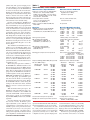
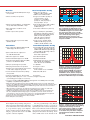
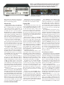
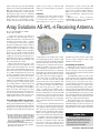
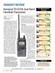
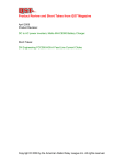
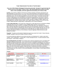
Product Review and Short Takes from QST Magazine March 2008 Product Reviews: Yaesu FT-950 HF and 6 Meter Transceiver Array Solutions AS-AYL-4 Receiving Antenna Short Takes: QSO Wizard: Mac OS X Amateur Radio Visual Aid Copyright © 2006 by the American Radio Relay League Inc. All rights reserved. Key Measurements Summary product review Yaesu FT-950 HF and 6 Meter Transceiver 129 128 140 20 70 20 kHz Blocking Gain Compression (dB) 97 2 98 70 140 2 kHz Blocking Gain Compression (dB) 90 I3 95 20 50 110 20 kHz 3rd-Order Dynamic Range (dB) I3 2 Reviewed by Norm Fusaro, W3IZ Assistant Manager, Membership and Volunteer Programs Department Before the official opening of the JARL Ham Fair in August 2007, hidden under a black veil, Yaesu’s latest player in the mid priced transceiver market waited for its introduction to the world. This is where I first saw the FT-950, the HF and 6 meter amateur transceiver that is being touted as a “baby FT-2000.” The FT-950 may be a scaled down version of Yaesu’s workhorse transceivers but it certainly is not stripped down. With 100 W output on all amateur bands from 160 to 6 meters, general coverage receive, built-in automatic antenna tuner and a host of other features found in competition class transceivers, there is no doubt that this new radio will fill a void in the company’s product line and in the hearts of radio amateurs looking for big rig performance in an economical package. First Impressions When the FT-950 is sitting side by side with the FT-2000, the inherent resemblance is striking but the similarity doesn’t stop at facial features. The ’950 is packed with many of the QRM-fighting and signal-enhancing features that many operators have come to know in the FT-2000 series and in Yaesu’s flagship FT DX 9000 series radios. 1 For example, the FT-950 includes digital noise reduction (DNR), which uses a variety of algorithms to separate signals from noise. It 1QST Product reviews, including the FT-2000, FT-2000D, FTDX9000D and FTDX9000 Contest, are available on the Web at www.arrl. org/members-only/prodrev/. also has a CONTOUR control, used to enhance the desired signal and distinguish it from noise and interference. The FT-950 is also capable of using optional accessories such as Yaesu’s Data Management Unit (DMU-2000) to provide a graphic image of the rig’s operation. It’s also got provisions for adding optional µ-Tune units, precision motorized preselector circuits that can enhance a weak signal or attenuate an interfering signal.2 I used the optional µ-Tune units with the ’950 and they had an obvious effect on received signals. Not being located near a strong broadcast station or other source of interference, I was unable to fully appreciate the preselector’s performance. Noticeably smaller than its big brother, the FT-950 is still a substantial piece of gear that makes a nice statement when sitting on the operating desk. One reason for the smaller form factor is the absence of an internal power supply. This can be a benefit to some people because many operators already own a power supply that is used to run several pieces of gear in the shack. I found that the ’950 worked fine using a big, heavy 35 A Astron analog supply or when juiced with a lightweight Yaesu FP-1023 switching supply. Weighing in at 21.6 pounds, the FT-950 is not what many would consider a “portable” rig, but with all of the big rig features in a smaller package I would consider this a remarkable field radio to be used in a variety of situations such as DXpeditions, Field Day or EOC operations. The front and rear feet 2The DMU-2000 and µ-Tune units were discussed in more detail in the FT-2000D Product Review in October 2007 QST. Mark J. Wilson, K1RO From March 2008 QST © ARRL Product Review Editor 71 50 110 2 kHz 3rd-Order Dynamic Range (dB) +16 I3 +21 +35 20 -40 20 kHz 3rd-Order Intercept (dBm) I3 2 -4 -40 +35 2 kHz 3rd-Order Intercept (dBm) T-R 50 25 10 Tx-Rx Turnaround Time (ms) I3 TX -20 -35 -35 Transmit 3rd-Order IMD (dB) I9 TX -20 -56 Transmit 9th-order IMD (dB) -70 pr028 80 M Key: Dynamic range and intercept values with preamp off. Intercept values were determined using –97 dBm references. 20 M Bottom Line The FT-950 HF/50 MHz transceiver fills a void in Yaesu’s product line. It should appeal to radio amateurs looking for big rig performance in an economical package. [email protected] are sturdy with the front adjustable, so you shouldn’t have any trouble finding a comfortable operating position. In order to offer a transceiver with all of the superb features that are found in the bigger rigs, cost had to be cut somewhere on the FT-950 without sacrificing operation. Jettisoning the aforementioned power supply contributed to the economy of the ’950 as did replacing the FT-2000’s analog meter with an LED bar graph style multimeter that is part of the brightly colored and easy to read display. The meter functions are still there — ALC, speech compression level, SWR and final amplifier drain current and voltage. Perhaps one of the most noticeable changes (or perhaps not, depending on your operating style) is the exclusion of a second receiver. Many operators probably would not consider losing a second receiver a big sacrifice in performance because the rig uses dual VFOs, essential for split operation when working DX stations whose band allocations are different than your own. Working a DX station that is calling CQ takes just takes a quick push of the A-B button to move the DX frequency to the sub VFO, allowing the operator to tune the main VFO to the frequency that the DX station is listening to. Another quick poke at this button returns the rig to the appropriate receive and transmit frequencies, ready to break the pileup. A nice feature of the FT-950, also found on the FT-2000, is the TXW button. Holding the TXW button, conveniently located to the lower left of the main VFO, momentarily swaps the two VFOs allowing the operator to monitor the rig’s transmit frequency. Releasing the TXW button returns the VFOs to the proper TX/RX configuration for working split. Because this is a momentary feature and does not permit the rig to transmit when activated, the TXW should all but eliminate the “wrong VFO” syndrome. The FT-2000 rear panel includes connections for an external VHF/UHF transverter and for an external receive antenna. Both are absent from the FT-950’s rear panel, and that may or may not be an issue depending on your on-air activities. Ergonomics The ergonomic design of the FT-950 makes it a real pleasure to operate. Some of the lesser-used controls are positioned out of the way but remain fully accessible when needed. The more frequently used features utilize larger buttons and knobs and are placed within easy reach. Routine maneuvers, such as toggling between two antenna inputs, simply requires pushing a button located on the front of the radio. The large knurled rubber knob of the main VFO makes tuning signals easy and comfortable. Dial torque is easily adjustable. Similar to the FT-2000 and FTDX9000 transceivers, the FT-950 has a medium sized tuning knob on the lower right of the front of the rig. In the larger radios this knob is used to tune the sub receiver and VFO B. The FT-950 uses this CLAR/VFO B knob for the clarifier (RIT/XIT) or to tune VFO B when the second VFO is activated. Just as on the larger rigs the CLAR/ VFO B knob is also used to select memory channels or to navigate through the general coverage receive bands in menu selectable 1 MHz or 100 kHz increments. The AF GAIN knob and its concentric partner, RF GAIN, use larger than normal knobs, making fine adjustments smooth and easy. A similar sized knob labeled SELECT is to the left of the main VFO, positioned beneath a bank of six buttons that activate the IF shift, IF width, contour, notch filter and optional A Look at the Field In the July 2007 Product Review, we compared some of the features and performance of the radios in the $2500 to $3000 range. With the introduction of the FT-950, there are now four desktop radios within $100 of $1500. They are listed in alphabetical order in Table A starting with the ICOM IC-746PRO, then the Kenwood TS-2000, the Ten-Tec Jupiter and finally the new Yaesu FT-950. This price range is above the entry level, but about half that of the middle ground radios looked at previously. Near this range there are other radios as well, but perhaps not quite direct competition. The new Elecraft K3 100 W kit starts just above this range, but we haven’t reviewed it yet. For most buyers, with usual accessory features, it will end up as competition in the next higher bracket. There are compact portable or mobile radios that are also close to this range, the ICOM IC-7000 perhaps the most obvious choice. The kit Elecraft K2/100 with a few options is in the same range, but both of these are a bit outside this desktop market segment. Either could fill that role, especially for smaller desks. Each of these radios offers 160 through 10 meter operation with a general coverage receiver and IF DSP. They all operate from an external 12.6 V supply. These radios offer distinct choices among the models that will make each appeal to hams with particular needs and interests. Perhaps the most dramatic difference is in V/UHF frequency coverage, which may be a decision maker for many potential buyers. I have summarized the major features and performance characteristics in Table A to make a comparison easier. Note that higher dynamic range values provide better rejection of the effects of nearby strong signals. Still, there are many subjective differences worth reviewing and all are on the ARRL members Web page in the original product reviews. — Joel Hallas, W1ZR, Technical Editor, QST Table A Key Differences Between the Contenders Feature Base Price Power Supply MF/HF/6 Meters IF DSP Dual Receiver 14 MHz BDR (20/5/2 kHz) dB** 14 MHz 3OIMD (20/5/2 kHz) dB** Antenna Tuner SWR Range Firmware Downloadable Electronic Memory Keyer Transmit Audio Equalizer IC-746PRO $1525 Included* Yes + 2 Meters Yes None 125/100/94 97/75/70 3:1*** No Yes Yes TS-2000 $1570 $135 Yes + 2 M, 70 cm Yes V/UHF AM-FM 126/103/87 94/69/66 3:1 Yes Yes Yes Jupiter $1549 $169 MF/HF only Yes None 123/94/93 85/69/67 10:1, $300 Option Yes Yes Yes FT-950 $1475 $170 Yes Yes None 128/111/98 95/91/71 3:1 Yes Yes Yes *Limited time offer, regularly $300. **Preamp off. ***2.5:1 on 6 meters. From March 2008 QST © ARRL µ-Tune units. The operator simply presses one of the buttons to choose which function to control and then presses the SELECT knob to activate or deactivate the selected feature. Turning the knob makes the adjustments. All settings are retained when moving from feature to feature and can be recalled. An improved feature not found on the big rigs is the CLEAR button that is used to return the selected function to its default setting. Pressing and holding the SELECT knob permits access to the CW memory keyer features. I found the keyer easy to program with standard CW paddles and easy to play back on the air. I felt that the record and playback functions could have been separated to avoid accidentally erasing one of the memories. This did not happen to me, but I can easily see how during the heat of battle some operators could overshoot the playback selections and land on a record option, hitting the SELECT knob before noticing the error. You can also use the optional FH-2 keypad to access the memory keyer. The multifunction SELECT knob also permits access to the FT-950’s digital voice keyer features if you’ve installed the optional DVS-6 Voice Memory Unit. With the DVS-6, you can record and play back five messages of up to 20 seconds each. The FH-2 keypad can be used to control the digital voice keyer functions as well. The keypad is more convenient to use than the SELECT knob and is a good investment if you use the internal voice or CW keyers a lot. Menu setup and operation is similar to the FT-2000 series, FT-450 and other recent Yaesu transceivers. Press the MENU button then use the SELECT knob to call up the menu items. The 118 menu items are arranged in groups. Press the SELECT knob and turn it to scroll through the various groups (DISPLAY, MODE-SSB, TX AUDIO and so on). When you have the right group, press SELECT again and then turn the knob to scroll through the related menu items in the group. Rotate the CLAR/VFO B knob to select among the settings for the menu item. Press and hold MENU for at least 1 second to store the new settings. With the limited front panel space, the FT-950 has only four dedicated rotary control knobs in addition to the TUNING and concentric AF/RF GAIN controls mentioned earlier. These controls are for MIC GAIN, keyer SPEED, MONI (monitor level) and SQL (squelch). Several traditional front panel functions have moved to menus. Transmitter power output adjustment (5 W to 100 W) is now controlled from a menu. That’s fine if you normally operate at one power level. It’s less convenient if you need to vary your power regularly. For example, you might need to reduce power temporarily to adjust an external power amplifier or manual antenna tuner for From March 2008 QST © ARRL Table 1 Yaesu FT-950, serial number 7K030158 Manufacturer’s Specifications Measured in the ARRL Lab Frequency coverage: Receive, 0.03-56 MHz; transmit, 1.8-2, 3.5-4, 5.3305, 5.3465, 5.3665, 5.3715, 5.4035, 7-7.3, 10.1-10.15, 14-14.35, 18.068-18.168, 21-21.45, 24.8924.99, 28-29.7, 50-54 MHz. Receive, as specified (sensitivity degrades below 1 MHz). Transmit, as specified. Power requirement: 13.8 V dc; receive, 2.1 A (signal present); transmit, 22 A (100 W out). Receive, 2.0 A; transmit, 18 A; tested at 13.8 V dc. Modes of operation: SSB, CW, AM, FM, FSK, AFSK. As specified. Receiver Receiver Dynamic Testing SSB/CW sensitivity, 2.4 kHz bandwidth, 10 dB S+N/N: 0.5-1.8 MHz, 4.0 µV; 1.8-30 MHz, 0.2 µV; 50-54 MHz, 0.125 µV. Noise Floor (MDS), 500 Hz bandwidth:* Preamp Off 1 2 1.0 MHz –109 N/A N/A dBm 3.5 MHz –120 –129 –136 dBm 14 MHz –119 –130 –137 dBm 50 MHz –119 –130 –138 dBm Noise figure: Not specified. 14 MHz, preamp off/1/2: 29/18/7 dB. AM sensitivity, 6 kHz bandwidth, 10 dB S+N/N: 0.5-1.8 MHz, 28 µV; 1.8-30 MHz, 2 µV; 50-54 MHz, 1 µV. 10 dB (S+N)/N, 1 kHz, 30% modulation: Preamp Off 1 2 1.0 MHz 12 N/A N/A µV 3.9 MHz 4.5 1.3 0.57 µV 50 MHz 5.1 1.4 0.56 µV FM sensitivity, 15 kHz bandwidth, 12 dB SINAD: 28-30 MHz, 0.5 µV; 50-54 MHz, 0.35 µV. For 12 dB SINAD: Preamp Off 29 MHz 2.2 52 MHz 2.7 1 0.58 0.75 2 0.27 µV 0.28 µV Blocking gain compression: Not specified. Gain compression, 500 Hz bandwidth:* 20 kHz offset 5/2 kHz offset Preamp off/1/2** Preamp off 3.5 MHz 129/127/126 dB 112/97 dB 14 MHz 128/127/127 dB 111/98 dB 50 MHz 125/125/123 dB 114/98 dB Reciprocal Mixing (500 Hz BW): Not specified. 20/5/2 kHz offset: –86/–69/–57 dBc. Two-Tone IMD Testing*** Band/Preamp Spacing Input level 3.5 MHz/Off 20 kHz –30 dBm –22 dBm Measured Measured IMD level IMD DR* –120 dBm 90 dB –97 dBm Calculated IP3* +15 dBm +16 dBm 14 MHz/Off 20 kHz –25 dBm –18 dBm 0 dBm –119 dBm 94 dB –97 dBm –39 dBm +22 dBm +21 dBm +20 dBm 14 MHz/1 20 kHz –35 dBm –25 dBm –130 dBm 95 dB –97 dBm +13 dBm +11 dBm 14 MHz/2 20 kHz –44 dBm –31 dBm –139 dBm 95 dB –97 dBm +4 dBm +2 dBm 14 MHz/Off 5 kHz –29 dBm –20 dBm 0 dBm –120 dBm 91 dB –97 dBm –40 dBm +17 dBm +19 dBm +20 dBm 14 MHz/Off 2 kHz –49 dBm –35 dBm 0 dBm –120 dBm 71 dB –97 dBm –33 dBm –13 dBm –4 dBm +16 dBm 50 MHz/Off 20 kHz –33 dBm –25 dBm –119 dBm 86 dB –97 dBm +10 dBm +11 dBm Second-order intercept: Not specified. FM adjacent channel rejection: Not specified. operation on different bands. The VOX adjustments and CW delay are also set via menus. As on other Yaesu transceivers, the ’950 has a C.S (custom switch) button that you can program for quick access to a menu item (your choice, but only one at a time). This is helpful, but some operators might prefer Preamp off/1/2: +71/+71/+71 dBm. 20 kHz offset, preamp on: 29 MHz, 77 dB; 52 MHz, 79 dB. several C.S buttons, or better yet, the ability to assign different functions to one or more of the rotary knobs. For example, some ops might get more use from VOX DELAY or RF POWER controls than from SQL or SPEED. You’ll need a special 10-pin plug for the relay and ALC connections to an external QS0803-PR01 Receiver Receiver Dynamic Testing FM two-tone, third-order IMD dynamic range: Not specified 20 kHz offset, preamp on: 29 MHz, 77 dB†; 52 MHz, 78 dB; 10 MHz offset: 52 MHz, 85 dB. S-meter sensitivity: Not specified. S9 signal at 14.2 MHz: preamp off, 110 µV; preamp 1, 31 µV; preamp 2, 7.1 µV; 50 MHz, preamp off, 136 µV; preamp 1, 38 µV; preamp 2, 6.7 µV. Squelch sensitivity: SSB, 0.1-1.8, 50-54 MHz, 2.0 µV; FM, 28-30, 50-54 MHz, 1.0 µV. At threshold, preamp on: SSB, 14 MHz, 0.55 µV; FM, 29 MHz, 0.51 µV; 52 MHz, 0.44 µV. Audio output power: 2.5 W into 4 Ω at 10% THD. 3.1 W at 0.5% THD into 4 Ω (max vol). IF/audio response: Not specified. Range at –6 dB points, (bandwidth): CW (500 Hz): 449-948 Hz (499 Hz),‡ Equivalent Rectangular BW: 493 Hz; USB: 144-1707 Hz (1563 Hz); LSB: 146-1742 Hz (1596 Hz); AM: 114-1826 Hz (1712 Hz). Spurious and image rejection: HF, 70 dB; 50 MHz, 60 dB. First IF rejection, 14 MHz, 84 dB; 50 MHz, 62 dB; image rejection, 14 MHz, 118 dB; 50 MHz, 71 dB. Transmitter Transmitter Dynamic Testing Power output: HF & 50 MHz: SSB, CW, FM, 100 W (high); AM, 25 W (carrier) HF: CW, SSB, FM, typically 108 W high, 4 W low; AM, typ. 42 W high, 3 W low; 50 MHz: CW, SSB, FM, typ 99 W high, 4 W low; AM, typ. 26 W high, 2 W low. Spurious and harmonic suppression: HF, >60 dB; VHF, 65 dB. HF, 62 dB; VHF, 68 dB. Meets FCC requirements. -40 SSB carrier suppression: >60 dB. HF, 61 dB; VHF, 65 dB. -60 Undesired sideband suppression: >60 dB. HF, 65 dB; VHF, 68 dB. Third-order intermodulation distortion (IMD) products: –31 dB PEP at 100 W 3rd/5th/7th/9th order (worst case band): HF, –35/–40/–53/–56 dB PEP; VHF, –34/–42/–52/–59 dB PEP; CW keyer speed range: Not specified. 4 to 56 WPM. CW keying characteristics: Not specified. See Figures 1 and 2. Transmit-receive turnaround time (PTT release to 50% audio output): Not specified. S9 signal, 25 ms. Unit is suitable for use on AMTOR. Receive-transmit turnaround time (tx delay): Not specified. SSB, 39 ms; FM, 36 ms. Composite transmitted noise: Not specified. See Figure 3. 0 0.01 0.02 0.03 0.04 0.05 0.06 0.07 0.08 Figure 1 — CW keying waveform for the Yaesu FT-950 showing the first two dits in full-break-in (QSK) mode using external keying. Equivalent keying speed is 60 WPM. The upper trace is the actual key closure; the lower trace is the RF envelope. (Note that the first key closure starts at the left edge of the figure.) Horizontal divisions are 10 ms. The transceiver was being operated at 100 W output at 14.2 MHz. QS0803-PR02 0 -20 -80 -100 14015 14017 14019 14021 14023 14025 Figure 2 — Worst-case spectral display of the Yaesu FT-950 transmitter during keying sideband testing. Equivalent keying speed is 60 WPM using external keying. Spectrum analyzer resolution bandwidth is 10 Hz, and the sweep time is 30 seconds. The transmitter was being operated at 100 W PEP output at 14.2 MHz. Size (height, width, depth): 4.5 × 14.4 × 12.4 inches; weight, 21.6 pounds (not including power supply or accessories). Price: Price: FT-950, $1500; DMU-2000 data management unit, $1000; µ-Tune kit A (160), B (80/40) or C (30/20 meters), $500 each. *Initial Lab testing revealed lower than expected IMD dynamic range test results. Subsequent testing of two additional FT-950s indicated that our particular unit was defective. The Noise Floor, Blocking Gain Compression and Two-Tone IMD Testing results shown here are from another off-the-shelf FT-950, s/n 7L040087. **When preamp 2 is switched in, the default roofing filter becomes 15 kHz. It is 3 kHz with preamp off or preamp 1. Measurements were made with default settings. ***ARRL Product Review testing now includes Two-Tone IMD results at several signal levels. Two-Tone, 3rd-Order Dynamic Range figures comparable to previous reviews are shown on the first line in each group. The “IP3” column is the calculated Third-Order Intercept Point. Second-order intercept points were determined using –97 dBm reference. †Measurement was noise-limited at the value indicated. ‡Varies with pitch control setting. QS0803-PR03 0 -20 -40 -60 -80 -100 -120 -140 -160 -180 102 linear amplifier. To speed things along, Yaesu offers an optional cable with the 10-pin plug on one end and bare wires on the other, ready to accept whatever plugs your amplifier requires. Another optional cable allows plugand-play operation with Yaesu’s VL-1000 “Quadra” solid-state amplifier. The 128 page FT-950 Operating Manual is well illustrated and does a good job of explaining the radio’s features and operation. There’s a lot to this radio, and it’s worth spending some time going through the manual and trying all of the features and settings. Yaesu offers a PDF version of the manual on the 103 104 105 106 Figure 3 — Worst-case spectral display of the Yaesu FT-950 transmitter output during composite-noise testing. For the red trace, power output is 100 W at 14.2 MHz. The carrier, off the left edge of the plot, is not shown. This plot shows composite transmitted noise 100 Hz to 1 MHz from the carrier. From March 2008 QST © ARRL Figure 4 — The FT-950’s rear panel includes connections for two antennas, a linear amplifier, and digital mode interface. Other jacks allow for plugand-play connection to Yaesu optional µ-Tune units, data management unit, FC-40 external antenna tuner and VL-1000 power amplifier. Figure 5 — As with other current Yaesu HF transceivers, the display shows filter selection, DSP settings and other important operating parameters at a glance. Web, ideal for searching for specific items or printing a few pages of menu commands to keep at your operating position. FM operation on 6 meters and 10 meters is included. Repeater offset and CTCSS tone encode/decode are selectable via menus. Sounds Great Fighting QRM The transmitted audio on the FT-950 is beautiful right out of the box. For those who like to customize things, the ’950 provides a three band parametric equalizer that can tailor just about any microphone to match or modify any user’s voice characteristics. The FT-950 is very capable of transmitting a full-bodied, well articulated voice. With all of the variables and possible combinations of audio settings with the FT-950, you can also make the audio sound bad. Familiarization and practice with the audio equalization tools is necessary to achieve a desired result. The speech processor in the FT-950 is tricky and requires gentle adjustments to find the proper setting. It is better to rely on your ear or to check with a friend on a quiet band rather than depend on the front panel meter alone to make this adjustment. In addition to the CW memory keyer mentioned previously, the FT-950 includes menu selectable semi break-in and full breakin (QSK) operation. As shown in Figures 1 and 2, keying characteristics are very similar to the FT-2000, with no noticeable shortening of the first character in QSK mode. The menus offer several interesting options. You can enable CW keying while in the SSB mode, either on all bands or just on 6 meters. Although they’re not that common on HF, cross-mode contacts can be useful on VHF. This feature makes it convenient to call an SSB station on CW without changing modes and retuning if your SSB signal isn’t getting through. Another menu option allows you to set the frequency display to show the CW offset or not. Connections for RF frequency shift (FSK) RTTY or AF frequency shift (AFSK) RTTY and sound card modes and packet operation are handled though the rear panel RTTY/PKT jack, a 6 pin mini-DIN connector. The manual includes the pin-out diagram for this and the transceiver’s other connectors all on one page. RTTY parameters such as polarity, shift and tone set are all adjustable via menus. If a PTT connection isn’t available, you can use VOX to key the transmitter in the AFSK modes. The FT-950 provides many of the same receiver enrichment features that are found in the FT-2000 and FTDX9000 series radios. As with the larger radios, it takes some practice to become proficient at using these state-of-the-art digital processing features. The operator who takes the time to read the manual and become familiar with the FT-950 will surely appreciate all that this innovative transceiver has to offer. Filter selection is similar to the FT-2000. Initial selectivity is provided by 15, 6 and 3 kHz wide roofing filters. Roofing filter selection is handled by the R.FLT button, and you can choose any filter manually or let the radio make the selection automatically. Automatic selections are 15 kHz for AM and FM, 6 kHz for SSB and 3 kHz for CW and RTTY. The 15 kHz roofing filter is automatically selected regardless of mode when preamplifier 2 is selected or when the noise blanker is turned on. DSP bandwidth filtering allows a wide range of filter choices for the various modes. Bandwidth is variable in 100 and 150 Hz steps using the WIDTH control, or you can switch in a preset narrower bandwidth by pressing the NAR button. The default wide/narrow settings will work for many operators but it’s easy enough to fine-tune things to your liking. In addition to the standard IF SHIFT and WIDTH controls, the receiver includes several receiver gain settings. Using the IPO (intercept point optimization) switch, you can select one of two preamplifiers or turn the preamps off, whichever is most favorable to the current operating environment. The ATT switch selects from 6, 12 or 18 dB attenuators. In my review of the FT-2000D radio, I described the interference fighting features as “signal enhancing features.” Improving the desired signal and attenuating unwanted signals and noise is the perfect combination for great radio reception. Regardless of the operating situation, familiarization with all of the controls is vital to achieve maximum performance from the FT-950. From March 2008 QST © ARRL The CONTOUR and the DNR are two features that I used a lot on the FT-2000 and I have found them to do a tremendous job at being able to isolate a desired signal. Experimenting with these digital processors and getting to know the effect that they can have on signals is essential to be able to get the most out of the FT-950’s performance. The CONTOUR control allows the operator to move a “low Q notch” across the passband in order to boost or suppress certain frequency components in the IF passband. By altering the passband response, you can improve the readability of a desired signal. This feature is accessed with a push of a button and adjusted via the SELECT knob, and easily accessible menu settings determine the peak/null and width of the notch. In my opinion the CONTOUR control is one of the better tools for signal enhancement and one that I rely on heavily in daily use. For this reason I have chosen to make this the function of the C.S. (custom switch) that allows me to access the CONTOUR menu with a push of a single button rather than scroll through the menus. Noise Reduction System The digital noise reduction system (DNR) is a digital signal processing feature that uses 16 separate and unique processing algorithms designed to attack different noise profiles. The DNR can be quickly engaged with a push of a button but unlike the larger rigs the adjustments are made through the menu system. This does not hinder operation very much because the DNR is a feature that does not require constant adjustment. Like the FT-2000, the ’950 has two IF notch filters. A manual notch filter is turned on and off and adjusted with the SELECT knob. As on the FT-2000, we measured a notch depth of more than 60 dB, and the manually operated notch filter is very good for eliminating a single source of interference within the passband. There’s also a digital notch filter (DNF) intended to automatically clean up several tones at once. DNF is enabled by pressing SELECT knob and dialing up a menu choice to turn it off and on. Unfortunately, as we found during the FT-2000 reviews, the DNF doesn’t behave well when presented with multiple signals or noise in the passband. The FT-950’s DNF effectively notched a single tone by 60 dB when nothing else is in the passband, but with more than one tone, it sometimes adds audible distortion products and notches the upper tone by a varying amount. Also, DNF is either on or off regardless of mode, so when activated it notches out desired CW signals as soon as they are tuned in. DNF settings are stored in memory separately for each VFO. Summary Employing the latest digital technology found in more expensive transceivers, the FT-950 is well suited as a main radio, backup rig or as part of a SO2R or multioperator contest station. New HF licensees or casual operators will appreciate the rig’s basic operation while contesters, DXers, net operators and others will delight in the FT-950’s competition grade heritage. M a n u f a c t u re r : Ve r t ex S t a n d a r d , 10900 Walker St, Cypress, CA 90630; tel 714-827-7600; www.yaesu.com. Array Solutions AS-AYL-4 Receiving Antenna Reviewed by Mark Wilson, K1RO Product Review Editor As the days started to get shorter in late 2006, on a whim I decided to hang a 160 meter dipole from a convenient tree. It’s not much of an antenna, really — perhaps 35 feet high in the center and 15 feet high at the ends, fed with nearly 150 feet of RG-58 and RG-8X. But I managed to have quite a bit of fun with it in the 160 meter contests sponsored by ARRL and CQ. Running barefoot, it was a thrill to work some West Coast and DX stations. I called anyone I could hear, no matter how strong they were. Sometimes they heard me, sometimes they didn’t. I even was able to put together some decent runs during the contest. Many nights the band was noisy, often a constant S7 to S9. It was difficult to hear weaker stations through the noise, the loud static crashes and the jumble of massive signals from nearby stations. Sometimes I used 12 to 18 dB of attenuation in my receiver just to make it palatable. I really needed to look into a dedicated low-noise receive antenna. Over the summer I picked up a copy of ON4UN’s Low-Band DXing and spent a few evenings poring over the detailed chapter on receiving antennas.3 John describes and evaluates antennas ranging from simple to awe-inspiring. Although Low-Band DXing make it clear that other (bigger) receiving antennas such as Beverages and vertical arrays offer better performance, I settled on a small terminated loop mainly because of its small footprint and ease of construction. Array Solutions K9AY Loop System Array Solutions offers a turnkey version of the popular terminated loop receiving antenna first described by Gary Breed, K9AY, in September 1997 QST.4 Consisting of two triangular wire loops about 85 feet long, hung 3J. Devoldere, ON4UN’s Low-Band DXing, 4th ed. Available from your ARRL dealer or the ARRL Bookstore, ARRL order no. 9140. Price, $39.95 plus shipping.Telephone 860-594-0355, or tollfree in the US 888-277-5289; www.arrl.org/ shop/; [email protected]. 4G. Breed, K9AY, “The K9AY Terminated Loop — A Compact, Directional Receiving Antenna,” QST, Sep 1997, pp 43-46. at right angles to one another from a single 25 foot high support, Gary’s antenna caught the imagination of many suburban low-band operators. From the center of the antenna, you need just 15 to 20 feet in four directions, making it possible to put up on a small lot. Some switching, a good ground rod, a variable termination resistor and a 9:1 matching transformer are required to make the antenna work. Depending on your receiver’s sensitivity, you may need an external preamplifier. For this review, we purchased the ASAYL-4 controller and AS-AYL-4 MW wire/mast kit from Array Solutions. The controller, manufactured by Wolf RF Systems, consists of indoor and outdoor units. The indoor unit houses the control circuitry, a 15-dB gain preamplifier and a bandpass filter designed to pass 160 and 80 meter signals but reject those from AM and shortwave broadcast band transmitters. The weatherproof outdoor unit, which mounts at the antenna base, is for switching relays, matching transformer and termination resistors. You can use the controller with your own loops, but we tried the mast/wire kit from Array Solutions. The kit includes a fiberglass mast, wire, guy rope, insulators and all the hardware in one convenient package. Everything is cut to length and ready to assemble. You can also order the kit without the mast. In addition to the material supplied by Array Solutions, you need to provide a coaxial feed line, a 6 conductor control cable (20 gauge wire for runs up to 250 feet) and an 8 foot long, 5⁄8 inch diameter ground rod. A local home center had ground rods and some sprinkler wire perfect for the control cable (seven 18 gauge conductors, with a jacket suitable for direct burial). Assembling the Antenna UPS dropped off two boxes, one with the controller and one with the mast/wire kit. All of the pieces were clearly described in the manual and a quick inventory showed nothing missing. I assembled the antenna over the course of three afternoons the week before Thanksgiving. My heavily wooded lot means that antenna projects generally start with a chainsaw. The first afternoon was devoted to clearing and disposing of a couple of trees and some brush behind the garage and driving the ground rod. Unfortunately I hit a rock after driving the ground rod in 4.5 feet (in this part of New England, I was glad to get that far). I ended up cutting the rod at ground level and later installed a few radial wires under the loops as suggested in the manual. The ground rod also serves as the base for the mast. First you slip a piece of thick wall aluminum tubing over the rod and secure it with supplied bolts. Next comes an aluminum ring that slides over the tubing and fastens Bottom Line The AS-AYL-4 receiving antenna system from Array Solutions is an effective way to improve your listening experience on the low bands, especially if space is limited. From March 2008 QST © ARRL -20 QS0803-PR06 -30 -40 dB -50 -60 -70 -80 1 1.5 2 2.5 3 3.5 4 4.5 5 5.5 6 6.5 7 MHz Figure 6 — Response of the preamplifier and bandpass filter in the AS-AYL-4 loop controller from 1 to 7 MHz as measured in the ARRL Lab. The filter is designed to attenuate unwanted signals in the AM broadcast band below 1.8 MHz and in the shortwave broadcast bands above 4 MHz. with set screws. The bottom of the mast rests on this ring, which has a series of holes for attaching a ground wire from the relay box and for hooking up radial wires. The mast and loops went together on the second afternoon. The loops are made from 88 feet of 13 gauge insulated, stranded wire. The fiberglass mast is four sections, each 6 feet long, 1.5 inches OD, with an 1 ⁄8 inch wall. You build the antenna from the top, first stringing the loop wires through a plastic guy ring that slips over the top section. Then you slip in the next mast section from the bottom. At this point, the instructions say to get a friend to hold the mast while you finish assembly. The next steps are attaching 1⁄8 inch Dacron rope guy lines to another guy ring, slipping that over the top of the third mast section and adding this section to the mast assembly. At this point you slide insulators over the loop wires and finish assembling the guy ropes and fasteners using prescribed dimensions. Then you hammer in the supplied guy anchor stakes at the 90° points (northeast, northwest, southeast, southwest) and loosely attach the guys. Finally you lift the assembly, slide in the last mast section, and set it on the ground rod mount. The mast seemed fairly sturdy and my wife wasn’t all that excited about continuing to work outside on a cloudy 25° day, so I kept going by myself. While adjusting the guys, I pulled the top of the mast a little too far out of vertical and it fell over, cracking a couple of the mast sections at the joints. Ouch! I was able to repair and reinforce the mast joints with some electrical tape and hose clamps, but do yourself a favor and follow the instructions. The mast is perfectly capable of supporting itself and the antenna when assembled as directed. Some of the dimensions didn’t come out exactly as shown in the drawing, but after From March 2008 QST © ARRL some back and forth and moving the guy stakes a bit closer to the mast, I got the guys adjusted and the mast plumb. I spent the third afternoon attaching the switch box to the mast, attaching the loop ends and ground wire to the appropriate terminals, and running about 200 feet of feed line and control cable. The control box needs 12 V dc at 400 mA and a coax jumper to the receive antenna jack on your transceiver. The control box used a phono jack for the receiver connection and an SO-239 UHF type coax jack for the loop feed line. Putting the Loops to Work With the wiring finished, there wasn’t much left to do but turn it on and start listening. There is only one adjustment — the eight-position TERMINATION resistance switch. As explained in the manual and shown in more detail in the original QST article, the K9AY loop horizontal radiation pattern has a very broad front lobe with a deep null off the back. The null in the vertical pattern is deepest at around 30 to 40° elevation. The termination resistance establishes the optimum front-to-back ratio, and the optimum value varies with local ground conditions and frequency. After some experimentation over a couple evenings, I couldn’t improve on the suggested default values for 160 and 80 meters. On air results were quite interesting. The first thing I noticed was the absence of noise and the clarity of desired signals. Listening on the dipole, with S-7 or stronger noise most of the time, it’s a struggle to hear weak stations. Not so with the loops. Although signals are significantly weaker, with the noise gone they clearly stand out and are easy copy. My receiver is sensitive enough that I use the preamplifier/filter in the loop controller perhaps half the time on 160 meters and only occasionally on 80 meters. Sometimes the antenna, with the preamp/filter off, improves listening when 40 and 30 meters are noisy. The loops exhibit noticeable directivity and are effective in reducing the strength of signals off the back. The null seems to range from about two S-units to five or six S-units depending on propagation and my distance from the undesired signal. One interesting question arose a couple weeks after installation. Winter arrived with a bang in early December, and four storms in a row deposited about 24 inches of snow on the ground, covering the lower loop wires. A quick consult with ARRL’s antenna expert Dean Straw, N6BV, reassured me that snow is actually not very conductive and likely would not noticeably affect the pattern or create additional losses. We have even more snow on the ground as this is written, and the antenna still works. The outdoor relay box is Figure 7 — The green fiberglass mast, black wire and black Dacron guy ropes all help the assembled AS-AYL-4 MW mast/ wire kit blend into the background. The gray relay box is mounted several feet off the ground with the ends of the loop wires attached to posts on top. still above the snow line, but the white stuff accumulated on top where the loop wires attach to exposed stainless steel machine screws. The box seems to be well sealed against weather, but I decided to add a plastic bag to keep the snow away. After using the K9AY loop system for a month, it would be difficult to go back to listening on my dipole. After improving my transmit antenna next summer I may want to try a bigger receive antenna, but for now I can hear more DX than I can work with my low dipole and 100 W. If you’d like to hear better on 160 and 80 meters, and especially if space is limited, the K9AY loop system from Array Solutions is worth a close look. Array Solutions recommends their AS-196 or AS-197 receive front end protector for those with a close by transmit antenna. The two are similar, except the 197 model also includes a lightning arrestor. Distributor: Array Solutions, 350 Gloria Rd, Sunnyvale, TX 75182; tel 972-203-2008; www.arraysolutions.com. Price:AS-AYL-4 controller, $325; AS-AYL-4 MW mast/wire kit, $195 ($110 without the mast); AS-196, $38; AS-197, $58. short takes QSO Wizard: Mac OS X Amateur Radio Visual Aid permit you to save the log data in Cabrillo formats as required for ARRL and CQ HF and VHF contests. After Cabrillo formatting, the data may be printed, PDF’d, or copied and pasted into e-mail. After a contact, QSO Wizard has a cool QSL card generator that automatically completes all the contact information from the log, but allows you to personalize the card by using any image for the card’s background and by allowing you to include individual remarks regarding the contact. You can print the card for real mail or PDF it for e-mail. For future contacts, QSO Wizard has a scheduling feature that allows you to set up one-time and recurring on-the-air skeds. You can configure the software to alert you of each sked 1 to 15 minutes ahead of schedule, as you desire. Stan Horzepa, WA1LOU 1 Glen Avenue Wolcott, CT 06716-1442 [email protected] OrcaStar* Software bills QSO Wizard as a Mac OS X application that provides “visual aids to assist amateur radio operators in identifying, locating, selecting, beam pointing, scheduling, and logging contacts world-wide.” After you configure the software with your preferences, it is off and running with an easyto-use and pleasing-to-the-eye graphical-user interface (GUI) featuring an Earth globe display centered on your location. On three sides of the globe are the buttons and fields that you use to control the application. OrcaStar* Software built its Mac OS X QSO Wizard around an The globe displays the current easy-to-use and pleasing-to-the-eye graphical user interface night and day based on your local (GUI) featuring a global display of the Earth. time (and calculated from your Mac’s clock). The software also displays a location’s latitude and longitude. Reviewer’s Impressions The software augments the great circle Greenwich Mean Time (GMT) and the local Using QSO Wizard is very intuitive. I only time at the station you are in contact with or path display by also showing the approximate consulted the documentation to fine-tune the antenna beam width of its main lobe, as well software and to learn more in depth about its are attempting to contact. Point and click on the location of the as the effect on the backside of the beam. various features. The average user, that is, other station and the software displays the This display is fairly accurate because you someone not reviewing the software for QST, great circle path on the globe as well as in customize it according to the actual antenna can probably get by without ever looking at the numerical Azimuth field in the Contact you are using. the documentation. In addition to the Azimuth information, Data panel of the GUI. I like the global view of the Earth that If the location of the other station is in the the Contact Data panel also displays the other QSO Wizard features. This view gives you opposite hemisphere of your station location, station’s alternate call sign prefix (if any), a true impression of the planet and its relaselect Opposite Lat & Lon in the Display location (country/island, continent, state/ tionship to time, size, location and direction View pull-down menu and then point and province, city/town, ITU and CQDX zones, (especially direction) that no flat map projecclick on the location. The Continent selection maidenhead grid number, latitude, longitude, tion can provide. (Hey — Japan is really over in the Zoom pull-down menu allows you to time zone) and distance (“range”) from your here, not over there!) view more details. This is especially helpful station. The Contact Data panel also indicates QSO Wizard is a fine addition to the softin areas where a bunch of small countries are if there is a QSL Service (bureau) in the other ware toolbox of any Mac ham shack. It looks grouped closely together, for example, South- station’s location. good and as a visual aid, looks are important. When your contact begins, you click east Asia, Europe and Latin America. Alternatively, you can obtain the path by on the QSO Begin button and the software It also works as advertised; I encountered no means of a call sign prefix look-up. Select Call creates and displays a new entry in its log, “gotchas” or program errors. The software Sign Prefix in the Select Category pull-down which pops out from the right side of the ran without a glitch and did not stop until I menu of the Locate panel, type the prefix in GUI. Some of the information appears in the told it to quit. the Search Prefix field, then press the Return log automatically, that is, the date and time key to display information about the location of the beginning and end of a contact. You The Fine Print OrcaStar* Software (www.orcastar.com) must manually input other information: frein the fields of the Contact Data panel. You can select a location from a database quency, mode and signal reports. At the end sells QSO Wizard for $49 and recommends (the software includes databases of DXCC of a contact, clicking on the QSO End button running the application at a minimum on Mac OS X version 10.2.7, but preferably on Mac entities, worldwide cities, cities by country, completes the logging of the contact. QSO Wizard includes templates that OS X version 10.4 (or later). and cities by state/province) or you can enter Steve Ford, WB8IMY QST Editor [email protected] From March 2008 QST © ARRL