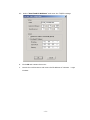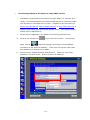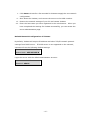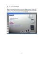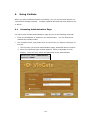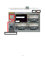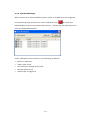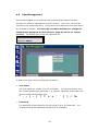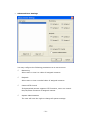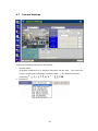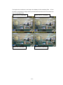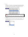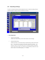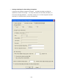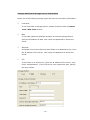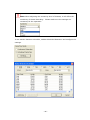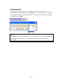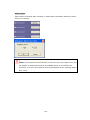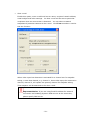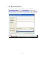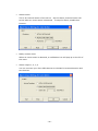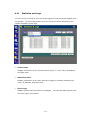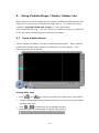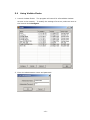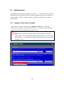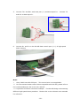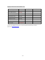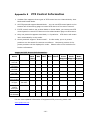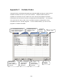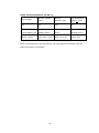
1
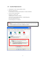
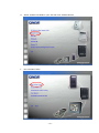
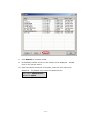
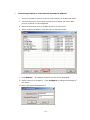
VioGate-340
IP Surveillance Server
User Manual
Version 1.0.0
©Copyright 2006.
QNAP Systems, Inc.
January 9, 2006
All Rights Reserved.
TRADEMARKS
QNAP® and VioGate™ are registered trademarks of QNAP Systems, Inc.
Microsoft®, Windows® and Internet Explorer® are registered trademarks of
Microsoft Inc.
All other brand or product names are trademarks of their
respective companies or organizations.
WARRANTY
QNAP guarantees all VioGate-340 IP surveillance servers have passed strict and
complete test and can operate normally in general condition.
In case of system
malfunction within the warranty period under normal operation of this product,
QNAP will provide product maintenance service.
NOTICE
This product can only operate indoor. Please do NOT place the product outdoor or
put any objects on the product.
-2-
Table of Contents
1.
Overview of VioGate.......................................................................5
1.1
About VioGate........................................................................ 5
1.2
Features................................................................................ 5
1.3
New Functions........................................................................ 6
1.4
System Requirements ............................................................. 7
1.5
Package Contents ................................................................... 8
1.6
System Overview.................................................................... 8
2.
Install VioGate ...............................................................................9
3.
VioGate CD-ROM...........................................................................16
4.
Using VioGate...............................................................................18
5.
6.
4.1
Accessing Administration Page.................................................18
4.2
System Configuration .............................................................26
4.3
System Settings ....................................................................28
4.4
Network Settings ...................................................................29
4.5
IP Security ...........................................................................31
4.6
User Management..................................................................32
4.7
Camera Settings....................................................................34
4.8
Recording Settings.................................................................39
4.9
Event Handling......................................................................44
4.10
Event Action Settings .............................................................50
4.11
Statistics and Logs.................................................................57
4.12
System Tools ........................................................................58
Using VioGate Player/ Finder/ Master Lite...................................61
5.1
Using VioGate Player..............................................................61
5.2
Using VioGate Finder..............................................................62
5.3
Using VioGate Master Lite .......................................................65
Maintenance.................................................................................68
6.1
Restart/ Shut down VioGate ....................................................68
6.2
Reset Administrator Password & Network Settings ......................69
6.3
System Update......................................................................71
6.4
Restore to Factory Default.......................................................71
Appendix A Terms and Glossary .........................................................72
Appendix B Dynamic Domain Name Registration................................74
Appendix C Connecting VioGate via PC ...............................................78
-3-
Appendix D Connecting VioGate via RS-422/ 485 Port .......................81
Appendix E PTZ Control Information ..................................................85
Appendix F VioGate Finder .................................................................86
Appendix G Using VioGate with IP Sharing Router .............................88
Appendix H GPIO Connections............................................................89
-4-
1.
Overview of VioGate
Note: Unless otherwise specified, VioGate mentioned herein refers to
VioGate-340 IP Surveillance Server.
1.1
About VioGate
VioGate-340 adopts advanced MPEG-4 image compression technology and
hardware compression chipset to minimize image and maintain DVD (720x480)
quality resolution for instant display. VioGate-340 is both a network image
server and a network video monitoring module.
The management software
VioGate Master supports monitoring and managing various VioGate products over
the network at the same time.
VioGate-340 can also partner with QNAP NAS
(network attached storage) server for backup and storage of remote video
recording.
1.2
Features
•
4-channel Full-D1 (720x480) instant MPEG-4 hardware compression
•
SMART recording mode for automatic adjustment recording speed
•
Supports 2 x 3.5” hard disks to preserve recording data for longer period
•
Built-in Gigabit network chipset for high speed data transfer
•
Multiple event alert triggering mode, e.g. motion detection triggering email or
SMS notification
•
Support multiple high speed dome cameras and control modes
-5-
1.3
New Functions
1.3.1 SMART Recording
VioGate-340 supports SMART Recording technology.
When the monitoring
screen stays the same for 5 minutes, VioGate will adjust the bit rate and frame
rate for recording automatically. When moving object is detected in the
monitoring screen, the system will automatically resume the bit rate and frame
rate to original settings.
For more information, please refer to Chapter 4.8.
1.3.2 Backup storage path
VioGate-340 provides two storage paths for saving recording and snapshot files.
You can select to save recording and snapshot files on local disk, NAS, remote PC
or an FTP site.
The second storage acts a backup storage path.
When the
primary storage path fails, currently recording files can be automatically switch to
the second storage within the time period specified by user to enhance continuous
and steady data storage.
For more information, please refer to Chapter 4.8.
1.3.3 Dual hard disk function
VioGate-340 supports two IDE hard disks at maximum and provides linear disk
volume to maximize storage capacity and increase the time for reserving
recording and snapshot files. For more information, please refer to Chapter 4.12.
1.3.4 PTZ camera
VioGate-340 supports pan/tilt/zoom cameras which are video cameras with
enhanced control mechanism. You can select one-click operation or press button
for continuous actions, and increase adjustable camera rotation angles in Camera
Settings page. For more information, please refer to Chapter 4.7.
-6-
1.4
System Requirements
•
Analog B/W or color camera (NTSC or PAL)
•
Network requirements:
RJ-45 Ethernet connection and dynamic or static IP address
•
Client side PC requirements:
Pentium 4 or above CPU
256MB system memory or above
VGA card (recommended resolution: 1024x768 pixels)
Microsoft Windows 2000/ XP
Internet Explorer 5.5 or above
Note: To connect VioGate by IE browser, “Security level for this zone” in
Internet Options must be set to Medium or lower.
-7-
1.5
Package Contents
•
4-channel MPEG IP surveillance server VioGate-340
•
Power cord
•
Network cable
•
CD-ROM (user manual and software inclusive)
•
GPIO connector
•
Quick Installation Guide
1.6
System Overview
Power Indicator
Hard Disk Indicator
Front View
GPIO
Connector
Rear View
Power Connector
1000 Mbps
Network Port
Power Switch
RS-232
Comport
RS-422/485 Comport
-8-
Video Input
Connector
Configuration Reset Switch
2.
Install VioGate
Please follow the steps below to install VioGate.
If you are not familiar with
network settings, consult your Internet service provider (ISP) or network
administrator for the details.
•
Connecting the server to local network with DHCP server
i
ii
iii
i.
Connect VioGate to the local network with the enclosed CAT-5 Ethernet
cable.
ii.
Connect camera to video input connectors of VioGate via video cable.
Up to 4 cameras can be supported.
iii.
Connect the power cord to VioGate and turn on the server.
-9-
iv.
Insert VioGate CD-ROM in your PC and click VioGate Series.
v.
Run VioGate Finder.
- 10 -
vi.
Click Refresh on VioGate Finder.
vii. All available VioGate servers in the subnet will be displayed.
Double
click on the correct device.
viii. Upon successful connection to VioGate, enter the user name and
password. The default user name and password are:
User name: administrator
Password: admin
- 11 -
•
Connecting VioGate to local network by static IP address
i.
Connect VioGate to a hub or router in local network via an Ethernet cable.
ii. Connect camera to video input connectors of VioGate via video cable.
Up to 4 cameras can be supported.
iii. Connect the power cord to VioGate and turn on the server.
iv. Insert VioGate CD-ROM in your PC and run VioGate Finder.
v. Click Refresh.
All available VioGate servers will be displayed.
vi. Select a server to configure. Click Configure to change the settings of
the server.
vii. Enter user name and password.
- 12 -
viii. Select “Use Fixed IP Address” and enter the TCP/IP settings.
ix.
Click OK and restart the server.
x.
Launch the web browser and enter the IP address of VioGate.
VioGate.
- 13 -
Login
•
Connecting VioGate to the Internet using ADSL service
i.
If VioGate is connected to the Internet through ADSL (i.e. dynamic IP is
used), it is recommended to use Dynamic DNS service to connect VioGate
with an easy-to-remember server name.
Register an account name on
http://www.dyndns.org, http://update.ods.org, or http://www.dhs.org, to
obtain a user name, password and a domain name.
(For further details,
please refer to Appendix B).
ii.
Please refer to Appendix C for details of connecting VioGate to PC.
iii.
Click on the setting icon
page, choose
on the left of the screen.
In the setup
“Network Settings” and select “Use broadband
connection to the Internet (PPPoE)”. Then enter the correct user name
and password to connect to the ADSL.
iv.
Check the box “Enable Dynamic DNS Service”.
password, and host name.
Enter the user name,
Select “Dynamic IP address”.
- 14 -
v. Click Save and wait for a few seconds for VioGate to apply the new network
configuration.
vi. Shut down the VioGate, and connect the server to the ADSL modem.
vii. Restore the network settings of your PC and restart VioGate.
viii. Enter the host name you have registered in the web browser.
When you
have completed the settings for VioGate successfully, you can access the
server administration page.
Default Network Configuration of VioGate
By default, VioGate will acquire IP address and other TCP/IP network protocol
settings from DHCP server.
If DHCP server is not supported on the network,
VioGate will use the following default settings:
IP Address: 192.168.0.1
Subnet Mask: 255.255.255.0
Login the server with the default administrator account:
User name: administrator
Password: admin
- 15 -
3.
VioGate CD-ROM
QNAP provides different software for various surveillance products. When using
VioGate-340, you will need to install VioGate Finder, VioGate Player, and VioGate
Master Lite. To use these programs, click VioCard-300.
- 16 -
You may select to install three programs dedicated for more convenient use of
VioGate-340.
After installing the programs, you can find the shortcuts on the
desktop of your PC.
Run these shortcuts to use the programs.
Field
Description
VioGate Finder
To find all available VioGate servers on the same network
VioGate Player
To view recorded data of all cameras
VioGate Master Lite
To monitor multiple VioGate servers available on the
same network
- 17 -
4.
Using VioGate
When you have installed VioGate successfully, you can use the web browser to
connect and manage VioGate.
VioGate supports Microsoft Internet Explorer 6.0
or above.
4.1
Accessing Administration Page
You can access VioGate administration page by one of the following methods:
•
Enter the IP address of VioGate in the web browser.
You can find the IP
address by VioGate Finder.
•
Run VioGate Finder, and double click on the server you want to configure on
the list.
i. The first time you access administration page, download ActiveX control.
ii. When the following login window appears, select a language for web
display.
Enter the user name and password of the administrator.
Default user name: administrator
Password: admin
- 18 -
iii. Upon successful login to the server, click
on the left column of the
monitoring page to enter system configuration page.
Help
Select display mode
Playback
System configuration page
- 19 -
Logout
4.1.1 Display Mode
You can select the desired display mode for the monitoring page.
Button
Description
View Single Camera
Adjust Window Size
Full-Screen Mode
Picture-in-Picture Mode
Quad Mode
Sequential Mode
Login VioGate as an administrator, you can click the button
to access
system administration page to view and modify all settings.
4.1.2 Manual Recording Video
Click
to record the selected camera’s live video to local PC.
Click the button
again to stop recording. The recorded files will be saved as vg3 format.
play the files with VioGate Player in the CD-ROM.
4.1.3 Manual Snapshot Taking
Click
to save a still image file to the computer.
- 20 -
You can
4.1.4 System Warnings
When events set in Event Handling section (refer to Chapter 4.9) are triggered,
the monitoring page will show an event notification icon
to inform the
administrator on the current status of the server. Double click the warning icon to
view the detailed description.
Event notification will be shown in the following conditions:
•
Motion is detected
•
Video input is lost
•
Connection to storage device fails
•
Storage space is full
•
Alarm input is triggered
- 21 -
4.1.5 Playback Video Files
To playback video files recorded, click
to enter the video playback page.
Back to live video
Help
Logout
Adjust screen view
Full view
Snapshot
Play/ Pause
Stop
Frame by frame
Fast Forward
- 22 -
•
Select Video Files
Select the following options to play video files:
Select the video file to play on the drop-down menu.
Search video files by specified date and time.
Search video files by events.
Select to play files stored on local PC.
Select files stored on the disk of VioGate.
•
Save Video Files
To save a playing file on a particular remote storage device, click
files can be saved as vg3 format.
- 23 -
.
The
•
Play Video Files
Use the following controls to play the video:
Play
Stop
Fast playing video file
Play video frame by frame
Adjust playback screen size
、
Take snapshot
- 24 -
4.1.6 Other Function Buttons
Start recording manually
Take snapshots manually
Adjust PTZ camera
Adjust PTZ camera focus
viewing angle
Function keys of PTZ camera
i.
: Adjust focusing lenses to minimize scope.
ii.
: Adjust focusing lenses to maximize scope.
iii. Click other buttons to adjust PTZ camera lenses.
iv. When VioGate uses Merit Lilin and Pelco D protocols, use your mouse to press
and hold the button to adjust camera direction pf the PTZ camera, you can
then move the camera angle continuously.
release the mouse.
- 25 -
To stop moving the angle, simply
4.2
System Configuration
The sections in System Configuration are shown below:
System Settings
Network Settings
IP Security
User Management
Camera Settings
Recording Settings
Event Handling
Statistics & Logs
System Tools
Server Name
Description
Software Version
Time Zone
Date & Time
Obtain IP address automatically
Assign IP address settings manually
Use broadband connection to the Internet (PPPoE)
Enable Dynamic DNS Service
Specify DNS Server
Enable Multicast
Allow All Connections
Allow Connections from the List Only
Deny Connections from the List
Add
Modify
Remove
Advanced Settings
Resolution
Bit Rate
Frame Rate
Brightness
Contrast
Hue
Saturation
Pan/Tilt/Zoom: Camera
ID, Mode, Protocol
Enable Recording
Disable Recording
Event Type
Event Action Settings
Active Users
Historical Users
Event Logs
System Update
Backup/ Restore
Restart/ Shutdown System
Hardware
Disk Tools
- 26 -
Icons on System Settings Page
System Settings
Network Settings
IP Security
User Management
Camera Settings
Recording Settings
Event Handling
Statistics & Logs
System Tools
- 27 -
4.3
System Settings
Enter the basic information for the system such as the server name, date and time,
and verify the current software version.
•
Server Name
Enter a unique server name for VioGate.
20 characters.
The server name can contain up to
The name cannot contain the following characters:
",;\:|*?><'`[]/%
•
Description
Enter a description of VioGate (126 characters at maximum), e.g. the
administrator name, department name, or the location of the server.
•
Version
The firmware version of VioGate will be displayed in this field.
•
Time Zone; Current Date and Time
Select the time zone according to the location of the server, and adjust the
date and time accordingly.
If you enter invalid date and time settings, you
may encounter the following problems:
9 If you are using web browser to view live video, the time displayed will not
be the same as the time shown on the personal computer.
9 Incorrect date and time information will be displayed when you try to play
video files or view event logs.
Note: Daylight time saving will be automatically adjusted for
different time zones.
- 28 -
4.4
Network Settings
Select the method VioGate uses to connect to the network. Enable multicast
function if necessary.
If you are not certain how your server connects to the
external network or about TCP/IP settings, contact your network administrator.
•
Obtain IP address settings automatically (DHCP)
Often used in conjunction with cable modem and corporate networks, the
system will obtain IP address and other TCP/IP information automatically.
If
your network supports Dynamic Host Configuration Protocol (DHCP), VioGate
will obtain IP address and other TCP/IP information automatically from the
DHCP server.
- 29 -
•
Assign IP address settings manually
Specify the IP address and other settings if you are using ADSL connection
service.
If the server’s external network uses ADSL service to connect to the
Internet, specify a valid IP address provided by the ISP. Enter the following
settings:
•
-
IP address
-
Subnet Mask
-
Gateway
Use broadband connection to the Internet (PPPoE)
PPPoE is often used in dial-up ADSL broadband service.
Enter the user name
and password provided by the ISP to connect to the Internet.
The server will use DHCP for network connection when PPPoE connection fails.
•
Enable Dynamic DNS service
Note: If you assign IP address settings manually to connect to the
Internet, and want to enable dynamic DNS service, specify a DNS
server.
To enable external access to VioGate by a domain name, activate dynamic
domain name service.
Apply for an account and register a dynamic domain
name from a dynamic domain name service provider.
Appendix B for further details.
Please refer to
After you have registered a dynamic domain
name and completed the setup, VioGate will automatically update the dynamic
IP address with the service provider’s server.
•
Specify DNS Server
To assign a specific DNS server, enter the server’s IP address.
•
Enable Multicast
Multicast enables the server to broadcast data to a specified group of clients
simultaneously to control network flow.
- 30 -
4.5
IP Security
Specify the connections to be allowed and denied to access VioGate. Choose one
of the following options to restrict access from a network or an IP address (host)
to the server:
•
Allow all connections (default setting)
Allow connection from all hosts to the server.
•
Allow connections from the following list only
Allow connection from hosts specified on the list only.
Note: When this function is enabled, you can only use PC that the IP
address is listed on the connection list to find VioGate by VioGate
Finder.
The IP address not included in the list will not be able to
detect VioGate not listed in allowed connections.
•
Deny connections from the following list
Deny connection from hosts specified on the list.
Note: When setting the connection lists, make sure your PC is
included in the list of hosts that connection to the server is allowed.
Otherwise when this setting is applied, VioGate will disconnect your PC
when you apply the new settings.
- 31 -
4.6
User Management
This section enables you to maintain user accounts and configure account
privilege for effective management of server access. The server can provide
services to any authorized users.
The system has a default account that cannot
be renamed or deleted. It is strongly recommended that you change the
administrator password the first time you login the server for system
security. The default user name and password are:
User name: administrator
Password: admin
To add a new user, enter the following information.
•
User name
The user name can contain up to 32 characters.
It is case-insensitive, and
can contain double-byte characters, e.g. Chinese, Japanese, and Korean, but
cannot contain the following ones:
"
•
,
;
\
:
|
*
? >
<
'
`
[
]
/
%
Password
The password is case-sensitive and can contain up to 16 characters.
recommended to set a password longer than 6 characters.
- 32 -
It is
•
Advanced User Settings
You may configure the following permissions to a user account:
9
Monitoring
Allow users to view live video of assigned cameras.
9
Playback
Allow users to view recorded video of assigned cameras.
9
Camera PTZ Control
If the attached camera supports PTZ functions, users can control
Pan/Tilt/Zoom functions of assigned camera.
9
System Administration
The user will have the right to change all system settings.
- 33 -
4.7
Camera Settings
Define the following settings for the camera:
i.
Camera name
20 English characters or 10 Chinese characters can be used.
The name can
contain only English alphabets, numbers, dash (-), or Chinese characters
(excluding
" , ; \ : | * ? > < ' ` [ ] / %)
ii. Resolution
- 34 -
The higher the resolution, the larger the display of the recording files.
If the
bit rate is unchanged, image quality will decrease but this will not increase the
size of recording files.
NTSC Full D1 (720x480)
NTSC Half D1 (720x240)
NTSC CIF (352x240)
NTSC QCIF (176x112)
- 35 -
iii. Bit rate
Select the bit rate for camera.
recording files.
Bit rate controls the storage space required by
You can refer to the approximate disk space required every
day by each channel for all bit rate options.
The total bit rate of the four
channels of VioGate will be affected by network bandwidth.
Note: MPEG-4 applies dynamic storage technology.
Storage capacity
varies according to the motion of image recorded by the camera.
iv. Frame rate
The faster the frame rate, the smoother the display image is displayed.
It is
recommended to set the frame rate as 15fps for optimized smoothness and
quality of the image.
- 36 -
v. Brightness
vi. Contrast
vii. Hue
viii.Saturation
You can adjust the best image for each channel of VioGate-340 when different
cameras are implemented.
If cameras of relatively less optimized default
settings are used, you can adjust the settings here for better image quality.
- 37 -
•
Pan/ Tilt/ Zoom
If the camera connected to VioGate supports P/T/Z function, you can operate
it with the control unit on the monitoring page.
To use P/T/Z function, configure the following settings:
9
Camera ID/ Speed
Select the ID of P/T/Z camera to control and the moving speed of
operation.
Camera ID can be 255 at maximum. Speed refers to the
moving speed of PT control unit. The larger the number, the faster the
moving speed. Please refer to the user manual of the camera for further
information.
9
Mode
If manual mode is selected, the camera will stay still and you can control
the angle via the monitoring page.
When preset mode is selected, you
can select preset points for PTZ camera.
PTZ camera will move
according to each preset position (1-10) every 10 seconds.
9
Protocol
The system supports multiple PTZ protocols: Computar YCH-02,
DynaColor, SONY VISCA, Merit Lilin, Panasonic WV-CS564, Honeywell
GC-655, Honeywell GC-755, VideoTrec, VideoTrec SP-8006W, and Pelco
D-Type.
Note: For further PTZ support information, please refer to Appendix E.
- 38 -
4.8
Recording Settings
To save live video and activate video playback function, enable recording function.
VioGate supports multiple-interval scheduled recording.
•
Recording Mode
9
Continuous Recording
VioGate will continuously record video stream to the storage.
9
Scheduled Recording
VioGate will start to record according to specified day, start time and end
time.
The system also supports overnight scheduled recording.
For
instance, when you set the start time for recording as 6pm on Monday
and the end time as 9am, the system will automatically defines the end
time as 9am on the following day, i.e. Tuesday.
- 39 -
•
Storage Settings for Recording/ Snapshot
Configure the storage settings of VioGate.
maximum as built-in storage.
VioGate provides two disks at
You may also select to use NAS, Windows, or
FTP as the storage platform. Firmware version 2.1.0 or later supports second
storage for recording when primary storage fails.
- 40 -
Storage Platform & Storage Access Information
Select one of the following storage types and enter the necessary information.
9
Local Disk
To use local disk as storage device, please format the disk in System
Tools—Disk Tools section.
9
NAS
To use NAS (Network Attached Storage) as external storage device,
enter the IP address of NAS, user name and password to access the
server.
9
Windows
If VioGate is set to save files to a share folder on a Windows server, enter
the IP address of the server, user name and password to access the
server.
9
FTP
To save files to an FTP server, enter the IP address of the server, user
name, and password. If the FTP server uses a particular port, specify
the port number.
- 41 -
Storage Path
Enter two different paths (folders) to store the recorded video files and
snapshot pictures.
Note:
i.
To save video files via FTP, enter a valid path.
ii. Both recording and snapshot files are stored in the same path.
Disk Full Settings
Select an action to be taken when available storage space falls under a
specified limit:
9 Overwrite the oldest recorded files
9 Stop saving newly recorded files
Note: When saving files on an FTP server, the system will not be able
to detect the storage size of the FTP server.
Therefore, you will not
be able to set the limit for storage space. The system will overwrite
old files or stop saving files when there is no available space on the
FTP server.
- 42 -
Switch storage space
Set the number of minutes VioGate should wait to switch to another storage
space when the original one fails. Note that you have to enable second
storage first before setting this function.
Smart Recording
Smart Recording is a function to optimize recording quality and recording
space of VioGate.
When Smart Recording is enabled, VioGate will determine
recording performance according to the change of input image. When the
screen does not change (nearly still image), VioGate will enter Smart
Recording mode after 5 minutes.
will drop at the same time.
The frame rate will drop to 1fps and bit rate
VioGate will determine the frame rate according
to the complexity of the monitoring image.
When a moving object enters the
monitoring area, VioGate will resume from Smart Recording mode and uses
previous frame rate and bit rate settings to acquire the best recording quality.
Note: Please make sure the camera is installed in an environment
where the brightness is higher than the minimum brightness required
by the camera to avoid too much noise which may lead to inability to
action of Smart Recording function.
- 43 -
4.9
Event Handling
When an event occurs, the system will automatically trigger alarms, and be
configured to ensure correct capturing and recording of video files.
are listed below:
•
Motion Detection
•
Video Input Loss
•
Network Failure
•
Storage Connection Failure
•
Storage Space Full
•
Alarm Input 1, 2, 3, 4
- 44 -
The events
Motion Detection
VioGate provides up to 256 detection areas to replace the monitoring screen of
your camera.
When motion detection is enabled, any movement detected in the
monitoring area will trigger a notification sent by the system.
focus for motion detection.
Select area of
Click Advanced under Motion Detection, and select
the camera movement and its dissection. Then select the sensitivity of motion
detection for the specified area.
It is recommended to select higher sensitivity
level if the camera is located in indoor environment.
If the camera is located in
outdoor environment where motion often occurs, it is recommended to select
lower sensitivity level for motion detection.
VioGate also supports motion detection for multiple time periods according to your
selection.
- 45 -
Note: When adjusting the sensitivity level of VioGate, it will affect the
sensitivity of Smart Recording.
Please make sure the settings are
necessary for the operation.
To set motion detection schedule, enable Scheduled Detection and configure the
settings.
- 46 -
Video Input Loss
You can select different settings of notification when an image is missing from one
of the frames.
This notification will sound the alarms that you have programmed
when image source is missing.
Network Failure
When the Internet access of the video server is disrupted, an alarm will sound. In
addition to voice alert when Internet access is disrupted, all other notification will
be reactivated when Internet access is restored.
This does not include GPIO
connection installed on your own.
Storage Connection Failure
When the video server has difficulties in storing files, i.e. the power supply to the
main file server is interrupted, a system alarm will sound.
- 47 -
Storage Space Full
The system will sound when the free space falls below a preset limit.
To
customize the storage capacity, click Setting. Enter the capacity in percentage
in the window after the command function.
When you have input the capacity,
click OK and then Save.
Note: GPIO device supports only 0-24V (voltage).
use voltage of less than 24V.
It is recommended to
For further information, Appendix H GPIO
Connections.
- 48 -
Alarm Input
Select other command input function or make them notification alarms for other
actions or function.
Note: If you choose to store the files on an FTP server, the video server will
not be able to detect the amount of available space on the FTP server.
Therefore, you will not be able to set the percentage for the "Storage Space
Full" event.
- 49 -
4.10
Event Action Settings
You can perform multiple event actions for a single event, and connect GPIO
devices to generate alarms.
- 50 -
•
Recording
To activate recording function of particular cameras when an event action is
detected, enable Recording function in Event Action and modify the settings.
To specify the storage path for recording files, click Storage Settings.
- 51 -
Select the storage path for recording and enter relevant information.
Configure disk full settings and relevant action to take, i.e. overwrite the oldest
recorded files or stop saving newly recorded files.
Note that you can enable
second storage and configure the storage settings.
When video input loss detection is activated for a channel set for recording, in
case that channel, e.g. channel 1, loses video input, the consecutive channel,
channel 2, will replace the primary channel for recording.
- 52 -
•
Snapshot
To activate snapshot function of particular cameras when an event action is
detected, enable Snapshot function in Event Action and modify the settings.
To specify the storage path for snapshot files, click Storage Settings.
When video input loss detection is activated for a channel set for snapshot
taking, in case that channel, e.g. channel 1, loses video input, the consecutive
channel, channel 2, will replace the primary channel for taking snapshot.
- 53 -
•
Alert e-mail
Enable this option, enter a valid mail server name, recipient’s email address,
email subject and other settings. An alert e-mail will be sent to particular
recipients when an event action is detected. You can select to attach
snapshots of particular cameras in the e-mail.
Click Test to send an e-mail to
test the function.
When video input loss detection is activated for a channel set for snapshot
taking, in case that channel, e.g. channel 1, loses video input, the consecutive
channel, channel 2, will replace the primary channel for snapshot taking.
That snapshot will be attached to the alert e-mail.
Important Notice: If you are using fixed IP address for network
connection and enabling dynamic DNS service at the same time,
please specify DNS server.
- 54 -
•
Alert SMS (Short Message Service)
When an event action is detected, an SMS message will be sent to a particular
phone number.
You must purchase SMS package from TW SMS
(http://www.twsms.com/) or VOLA (http://www.vola.it/) to acquire user
name and password, and use the points for SMS service.
After entering all
necessary information, you can send a test message before saving the settings.
Important Notice: VioGate must be able to connect to the Internet.
- 55 -
•
Alarm buzzer
This is an internal buzzer of the server.
sound when an event action is detected.
Set the alarm, and the buzzer will
To step the alarm, disable this
function.
•
Notify remote client
When an event action is detected, a notification icon will pop up on the PC of
the users.
•
Alarm output 1, 2, 3, 4
You can connect up to four GPIO devices to VioGate for action detection and
set the alert.
- 56 -
4.11
Statistics and Logs
You can view the record of users currently logged on and previously logged on to
the system.
In event logs section, you can check all events detected by the
system and back up the logs.
•
Active Users
Display information of all currently active users, i.e. user name, IP address,
and login time.
•
Historical Users
Display information of all users who have logged in VioGate including user
name, IP address, and login time.
•
Event Logs
Display system warning and error messages.
all event logs in this section.
- 57 -
You can also back up and clear
4.12
System Tools
You can use the following system tools to configure VioGate.
•
System Update
You can download the latest system firmware from QNAP website
(www.qnap.com.tw) and update your system. Your system will acquire
enhanced functions or higher stability after system update. Please make sure
the firmware is correct and read the relevant release notes before update.
- 58 -
•
Backup/ Restore
You can back up and restore system settings and user information to your
computer, and reset the system to default.
•
Restart/ Shut down System
You can select to restart or shut down VioGate in this section.
When VioGate
is recording and the built-in disk is used to store recording files, please shut
down the server by this setting so that magnetic head of the hard disk will
resume to its place to avoid system malfunction due to sudden power
suspension. When the option Shut down System is selection, please turn
off the power of the server after 30 seconds.
- 59 -
•
Hardware
This option is enabled by default. When it is enabled, you can press the
configuration reset switch of the server for a few seconds until you hear an
alert sound, the administrator password and network settings will restore to
default.
After resetting the system, all connections to VioGate will be
allowed.
Note: If this option is disabled, you will not be able to reset system by
pressing the switch.
•
Disk Tools
In this section, you can select disk mode: single disk or dual disk linear.
You
can also view current disk status of VioGate and space available, format and
check the disk in this section.
Note: Dual disk linear can only combines the storage capacity of two
disks to lengthen the time for saving recording data but does not
provide RAID protection.
- 60 -
5.
Using VioGate Player/ Finder/ Master Lite
When selecting to record image files by VioGate, VioGate will automatically save
video files in vg3 format to a specified storage device.
The video files will be
named as yyyy-mm-dd hh-mm-ss.vg3 (i.e. year-month-date
hour-minute-second.vg3).
You can connect to VioGate and copy the video files
to PC, and launch VioGate Player to view the file content.
5.1
Using VioGate Player
Launch VioGate CD-ROM in your PC and install VioGate Player. When finished,
double click VioGate Player shortcut on desktop to run the program.
The
following screen will be shown:
Playing Video Files
•
Click
•
Use the function buttons on the bottom left corner of the screen to play, pause,
and
to select and remove the video files on the playlist.
and stop video files.
•
Click
•
Move the arrow on the slide bar to adjust video playing.
or
to adjust the size of playback window.
- 61 -
5.2
Using VioGate Finder
1. Launch VioGate Finder.
The program will search for all available VioGate
servers in the network. To modify the settings of a server, select an item on
the list and click Configure.
2. Enter the administrator name and password.
- 62 -
3. Enter the information for VioGate and click OK.
4. Click Details to view the information of VioGate.
- 63 -
5. To launch the searched result again, click Refresh.
6. To close the program, click Exit.
- 64 -
5.3
Using VioGate Master Lite
Software Features:
1. 1/4/9/12/16/20 channel simultaneous display
2. Supports 32-channel display at maximum
3. Supports picture-in-picture and rotational display
4. Free combination of monitoring screen
5. Remote monitoring high speed dome camera
6. Supports reception of alert messages from remote VioGate
7. Various warning modes
Install VioGate Master Lite from VioGate CD-ROM. Double click the VioGate
Master Lite shortcut to launch the program.
Enter the user name and password to login VioGate Master Lite.
Default user name: user
Password: user
- 65 -
The first time you use VioGate Master Lite, the program will search for all available
VioGate servers on the network.
You can also click Add to add VioGate server
manually.
Enter the IP address or domain name, port number, user name and password to
add the server for VioGate Master monitoring.
- 66 -
You can then use VioGate Master to manage multiple VioGate servers.
- 67 -
6.
Maintenance
VioGate has been specially designed to run 24 x 7. The server also provides a
dedicated power protection system to protect against system crash caused by
power outage.
Please read this section carefully for information of system
maintenance.
6.1
Restart/ Shut down VioGate
To shut down or restart VioGate, go to System Tools page.
instructions to restart or shut down the system.
Follow the
You can also shut down the
system by pressing the power button of the server.
Note: When recording is enabled, data will be written to hard disk
continuously. Do not shut down power supply directly or it will cause
disk damage.
Any improper operation of the system will lead to data
damage or loss.
- 68 -
6.2
Reset Administrator Password & Network Settings
If you forget the administrator password, you will not be able to login VioGate and
perform system administration.
To reset the administrator password and
network configuration of VioGate to default, please do the following:
1. Press the configuration reset button of VioGate for a few seconds until a beep
sound is heard.
The network configuration will be reset.
2. Connect VioGate via a web browser to configure the settings.
Login with the
default administrator name and password:
User name: administrator
Password: admin
Note: If the configuration reset button is disabled in System
Tools—Hardware Settings page, you will not be able to reset
administrator password and network configuration by pressing the reset
switch.
When allowed connections are set in IP Security and configuration reset
switch is disabled, you must remember the allowed IP addresses, user
account and password.
Otherwise you may not be able to find the
correct IP address of VioGate and reset the system.
VioGate must be
sent to QNAP to reset configuration and all data on the server will be lost.
- 69 -
- 70 -
6.3
System Update
When you have successfully registered the product, you will receive email
notification on firmware update from QNAP.
You can update the system and
enjoy new functions free.
To update VioGate firmware version, go to System Tools – System Update page.
Make sure you have obtained the latest firmware version. Browse and select the
appropriate image file and upload it to VioGate.
6.4
Restore to Factory Default
To restore VioGate to factory default, connect to the server via web browser.
to System Tools – Backup/Restore page and select to restore the system.
- 71 -
Go
Appendix A
Terms and Glossary
TCP/IP (Transmission Control Protocol/ Internet Protocol)
TCP/IP was originally developed by the Defense Department of the States to allow
dissimilar computers to talk.
Today, this protocol is used as the basis for the
Internet. Because it must span such a large distance and cross multiple, smaller
networks, TCP/IP is a routable protocol, meaning it can send data through a router
on its way to its destination.
DHCP (Dynamic Host Configuration Protocol)
It is a method for assigning a permanent Internet Protocol (IP) addresses or on
the fly to individual computers in an organization’s network.
Usually it is
performed by a DHCP server.
FTP (File Transfer Protocol)
This is a method of moving files from system to system using TCP/IP with FTP
application.
DHCP IP
A dynamic IP address is assigned to your computer by your ISP’s server so that
other computer servers can find your computer when you are connected to the
Internet.
This IP address changes because whenever your computer reconnects
to the Internet, a different IP address will be assigned to your machine.
Static IP
It is a fixed IP address assigned to your computer.
IP address is a 32-bit digit
used to differentiate each single entity on a network. The IP address is divided
into 4 groups of eight bits separated by dots, e.g. 192.168.0.1.
PPPoE (Point-to-Point Protocol over Ethernet)
The Point-to-Point Protocol over Ethernet (PPPoE) feature allows a PPP session to
be initiated on a simple bridging Ethernet connected to the client.
The session is
transported over ATM link via encapsulated Ethernet-bridged frames.
The
session can be terminated at either a local exchange carrier central office or
Internet service provider (ISP) point of presence.
- 72 -
DNS (Domain Name System)
Domain Name System identifies each computer as a network node on the Internet
using an Internet protocol address system to translate from domain name to IP
address and vice-versa.
DDNS (Dynamic Domain Name System)
Dynamic DNS (DDNS) service enables clients and servers to automatically
register themselves in the database without needing administrators to manually
define records.
Multicast
Multicast is the technique that allows network data from a single source to be
simultaneously transmitted to a selected set of destinations (also called a host
group).
A main advantage of multicast is that it saves network bandwidth by
sending only one copy of data over the network.
- 73 -
Appendix B
Dynamic Domain Name Registration
VioGate supports DDNS service provided by DynDNS, ODS, DHS, and DyNS.
For
example, you can go to the web site of DynDNS (http://www.dyndns.org/) and
register for a dynamic domain name. Configure and activate DDNS service, then
the Internet users will be able to access your VioGate via this dynamic domain
name.
When the ISP assigns a new WAN IP address, VioGate will update the new
address to the DynDNS server automatically.
Registration Procedure
Please follow the steps below to register a dynamic domain name.
Note: This guide is for reference only.
If there are any changes, please refer to
the instructions or documents on the web site.
1.
Open the browser and connect to http://www.dyndns.org/. Click Sign Up
Now to begin registration.
- 74 -
2.
Check the box “I have read and agree to the Acceptable Use Policy above”.
- 75 -
3.
Enter the user name, email address and password to create an account for
DDNS service.
Please verify your email address to receive the confirmation
message from the server.
Then click Create Account to proceed.
- 76 -
4.
If the following web page appears on the screen, your account has been
successfully created and a confirmation message has been sent to your
e-mail address.
Please follow the instructions in the e-mail to activate your
account within 48 hours.
5.
When you have finished the confirmation process, you can apply for your own
dynamic domain name.
- 77 -
Appendix C
Connecting VioGate via PC
To access VioGate by a PC, connect the computer to VioGate by a crossover cable.
Configure the network settings of your PC and VioGate in the same network
domain.
To connect VioGate by default IP address, please configure the network
settings of your PC as below:
IP address: 192.168.0.2
Subnet Mask: 255.255.255.0
Please follow the steps below to access VioGate by a PC. The example is based on
Windows XP.
1. Right click “My Network Places” shortcut on the desktop, and choose
“Properties”.
Right click your network device, and choose “Properties”.
- 78 -
2. Highlight Internet Protocol (TCP/IP), and click “Properties”.
- 79 -
3. Set the IP address and subnet mask as the following:
4. Restart your personal computer. Launch the web browser (Internet Explorer),
and enter the IP address of VioGate 192.168.0.1 in the address bar.
Upon successful connection to VioGate, enter the default user name and
password to login the administration page:
User name: administrator
Password: admin
- 80 -
Appendix D
Port
Connecting VioGate via RS-422/ 485
To connect the PTZ camera using the RS-422/485 port, you will need a cable to
connect the camera to the server, and a D-Type 9-pin connector.
The four
connectors for data transfer are shown in the picture below.
To make a communication control wire, follow the steps below (*):
1.
Prepare a D-Type 9-pin female header and the wires necessary for RS-485.
Cat.5E network cable will be used in this example.
transfer.
- 81 -
Take four wires for data
2.
Weld the wires to D-Type 9-pin female header.
3.
Cover the header carefully.
4.
VioGate header is finished.
- 82 -
5.
Connect TX+ and RX+ with twist pair (**) as data output D+. Connect TXand RX- as data input D-.
6.
Connect D+ and D- to the RS-485 data control input (***) of high speed
dome camera.
Note:
*
Sony VISCA uses RS-232 port. This control wire is not applicable.
**
For the communication control wires compatible with RS-485, please refer to
the recommended wire list in the user manual.
*** DynaColor D7720A is used as an example.
different high speed dome providers.
The RS-485 design varies among
Please refer to the relevant user manuals
for reference.
- 83 -
High Speed Dome Recommendation List:
Protocol Name
Interface
Preset Mode
Manual Focus
DynaColor 7720A
RS-485
╳
╳
Sony VISCA VI-D30
RS-232
╳
╳
Merit Lilin
RS-485
○
╳
Panasonic WV-CS564
RS-485
○
╳
Honeywell GC-755
RS-485
╳
╳
Honeywell GC-655
RS-485
╳
╳
Computar YCH-02
RS-485
○
○
VideoTrec
RS-485
○
╳
VideoTrec SP-8006W
RS-485
○
╳
Pelco D-Type
RS-485/422
○
○
For the most updated information of recommended high speed dome models,
please visit www.qnap.com.tw.
- 84 -
Appendix E
PTZ Control Information
1. VioGate-340 supports three types of PTZ control service: Manual Mode, Auto
Mode and Preset Mode.
2. All PTZ protocols support Manual Mode.
You can use PTZ control panel on the
bottom left of Monitoring page to control PTZ device of the active channel.
3. If PTZ control mode is set as Auto Mode or Preset Mode, you cannot use PTZ
control panel to control PTZ device on the administration page via IE browser.
4. Only one protocol supports Auto Mode, i.e. DynaColor.
PTZ device will rotate
360° automatically in this mode.
5. Some protocols support "Preset mode".
In this mode, up to 10 preset
positions can be stored for camera surveillance.
preset positions will be displayed in order.
Monitoring screen of the
Please refer to the list below for
further information:
Supported PTZ Protocols Information:
Protocol
Name
Interface
Baud
Rate
(bps)
Start
Bits
Stop
Bits
Data Parity
Bits Check
Manual
Auto
Preset
Focus
Mode
Mode
Support Support Support
Computar
YCH-02
DynaColor
D7720A
Honeywell
GC-655
Honeywell
GC-755
Merit Lilin
RS-485
4800
1
1
8
None
Yes
No
Yes
RS-485
9600
1
1
8
None
No
Yes
No
RS-485
9600
1
1
8
None
No
No
No
RS-485
9600
1
1
8
None
No
No
No
RS-485
9600
1
1
8
None
Yes
No
Yes
Panasonic
WV-CS564
Pelco
D-Type
RS-485
9600
1
1
8
None
No
No
Yes
RS-485/
RS-422
2400
1
1
8
None
Yes
No
Yes
Sony
VISCA
EVI-D30
VideoTrec
RS-232
9600
1
1
8
None
No
No
No
RS-485
9600
1
1
8
None
No
No
Yes
VideoTrec
SP-8006W
RS-485
9600
1
1
8
None
No
No
Yes
For the most updated information of supported PTZ protocols, please visit
www.qnap.com.tw.
- 85 -
Appendix F
VioGate Finder
VioGate Finder is a dedicated program provided by QNAP to help you search for all
available VioGate servers in your local network.
VioGate Finder shows all
available surveillance servers within the local network and displays the basic
information such as servers’ names, workgroups and IP addresses. You may also
set up the server name, date, time, and basic network configuration of the
surveillance server via this program.
To use VioGate Finder, you can run the
program in VioGate CD-ROM.
All surveillance servers
can be identified using a
unique server name
Set up server
name, date,
time, and basic
network
Indicates the IP
address of the
server
View detailed
information
about the
selected
Re-search
surveillance
servers in the
network
- 86 -
Version
Number
Server Type
Exit the
program
You may obtain
information such as
server name,
software version,
MAC address, and
basic network
configurations.
Enter the administrator name
and password. You can then
change the server name,
date, time, and basic network
configurations.
- 87 -
Appendix G
Using VioGate with IP Sharing Router
Configuration for the virtual server on an IP sharing router connecting to
VioGate: a fixed IP address mapping approach.
If VioGate is in the same network with an IP sharing router using a fixed IP address,
it can be accessed via some assigned ports of the virtual server on the IP sharing
router mapping to the given ports on VioGate.
Assign two different ports for
monitoring live video on VioGate and playing the recorded video files.
In this case, the following settings of the configuration for the virtual server on the
IP sharing router should be reset:
•
Monitoring live video
You can assign any available port on the IP sharing router to map to port 80
on VioGate.
•
Playing recorded video files
You can assign port 21 only on the IP sharing router to map to port 21 on
VioGate.
- 88 -
Appendix H
z
GPIO Connections
Connections for Input/ Output devices
GPIO Input/ Output
Connectors
Description of Output Connector (From left to right)
Cm1
Common 1
NC1
Normal Close 1
NO1
Normal Open 1
Cm2
Common 2
NC2
Normal Close 2
NO2
Normal Open 2
Cm3
Common 3
NC3
Normal Close 3
NO3
Normal Open 3
Cm4
Common 4
NC4
Normal Close 4
NO4
Normal Open 4
Description of Input Connector (From left to right)
In1
Input 1
Gnd
Ground 1
In2
Input 2
Gnd
Ground 2
In3
Input 3
Gnd
Ground 3
In4
Input 4
Gnd
Ground 4
- 89 -
z
Specifications for General Inputs
The general inputs can take DC voltage from 0~24V. Voltage above 24V is
not recommended.
Input
5 VDC
12 VDC
z
Voltage Range
Logic 0
0.5V Max
Logic 1
4.5V Min
Logic 0
0.5V Max
Logic 1
11V Min
Specifications for General Outputs
Relay Contact Ratings
Contact form
1 FORM C (SPDT)
Contact capacity
coil = 0.36W
Resistive load
1A/125 VAC
(cos θ = 1)
2A/24 VDC
Inductive load
0.3A/30 VDC
(cos θ = 0.4 L/R = 7 msec)
Rated carrying current
2A
Max allowable voltage
AC 120V. DC 60V
Max allowable current
2A
Max allowable power
48W
Contact material
Ag Alloy
- 90 -
Relay Coil Specifications (At 20˚C)
Normal Voltage
Normal
Coil Resistance
(VDC)
Current (mA)
(ohm + 10%)
5V
5V
66.7
75
Power
Pull-in
Drop-out Voltage
Max Allowable
Consumption (W)
Voltage (VDC)
(VDC)
Voltage (VDC)
About 0.36W
75% max 3.75V
10% min 0.5V
110% 5.5V
Coil Voltage
After connecting your external device, you can plug the connector into the
GPIO connectors on VioGate.
- 91 -