1
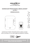
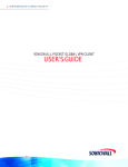
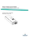
MODEL: AQ-DM-2
FILE NAME: IB-STI-IDK2A-4, 081001.cdr
R
iPod TM + MP3
TM
INSTRUCTION MANUAL
TM
iPod nano 3G
4G, 8G
TM
iPod touch
8G, 16G
TM
iPod classic
80G, 160G
TM
iPod 5G
30G, 60G, 80G
EXT
MHz
AQ-DM-2B
Keep Dry
Model AQ-DM-2B
Water/Dust Proof MP3/iPod TM Digital Media Locker TM
With
Floating RF LCD Wireless Remote Control
Please read this Instruction Manual
before installation and operation
LOCATION OF CONTROLS
TM
MP3/iPod Water/Dust Proof Digital Media Locker
TM
2
3
4
5
6
1
7
8
9
2-MD-QA
Keep Dry
10
Part
Description
1
2
3
4
5
6
7
8
9
10
Digital Media Locker Knob and Protective Door
Auxillary Locker Knobs
ON/Off Power Button
Water/Dust Protection Inner Gasket
3.5mm Aux Input Jack for MP3 Devices
Water Retarding and Drainage Groove
ON/Off Power LED
TM
Security Strap for Digital Media Devices (MP3/iPod )
TM
iPod Connector
TM
iPod TM Cradle (totally 5 iPod Cradle adaptors)
1
GETTING STARTED
CONTENTS:
Please make sure the following items are included.
a) AQ-DM-2 Digital Media Locker TM
b) Water/Dust Proof RF Wireless Remote Control
c) Ten (10) Finishing Covers for Stainless Mounting Screws
d) Five (5) iPod TM Cradles
e) Ten (10) Stainless Steel Wood Screws
f) Two (2) CR-2032 Batteries
INSTALLATION
Cable Connection
1. Plug and Play Connector: The AQ-DM-2 incorporates a 12 pin "plug
and play" connector harness. Owner product application options may
require an "optional" connector option. Contact your dealer for details.
2. FM Radio: The AQ-DM-2 has U.S. and Euro FM Frequency capability.
In both applications, make sure the FM Antenna is fully extended at the
highest possible level (Height) for best performance.
3. RCA Inputs: The AQ-DM-2 was developed with flexibility to use RCA
based Audio Media. The AQ-DM-2 has 1 set of RCA Audio Auxiliary
Inputs so you can connect other RCA based devices.
FM Radio
Antenna jack
12 pin
Harness Cable
Left Audio
Right Audio
RCA Output Jack
AQ-DM-2
Keep Dry
For non-OEM use, wiring harness must be
ordered separately
Part number AQ-UNH-1 or AQ-UNH-2
3
LOCATION OF CONTROLS
RF LCD Wireless Remote Control
EXT
A
MHz
B
Open
Close
I
I
Part
Description
A
B
C
Remote Control LCD
Remote Control Buttons
Battery Door.
C
Buttons
Music Mode
FM Radio Mode
Power
Press once: Change from Operation mode to Standby mode.
Press and hold: Change from Standby mode to Operation mode.
12V
trigger
Press once: Toggle external power
Press and hold: No change
Press once: Toggle external power
Press and hold: No change
Volume
up
Press once: Volume UP 3 decibels
Press and hold: Fast volume up
Press once: Volume UP 3 decibels
Press and hold: Fast volume up
Volume
down
Press once: Volume DOWN 3 decibels
Press and hold: Fast volume down
Press once: Volume DOWN 3 decibels
Press and hold: Fast volume down
FM Radio
Press once: Change to FM Radio Mode
Press and hold: No change
Press once: No change
Press and hold: No change
Memory +
Press once: No change to memory
Press and hold: No change to memory
Press once: Increase Memory Location
Press and hold: No change
Memory
Press once: No change to memory
Press and hold: No change to memory
Press once: Toggle to Memory Mode
Press and hold: No change
Memory -
Press once: No change to memory
Press and hold: No change to memory
Press once: Decrease Memory Location
Press and hold: No change
Music
Press once: No change to Ipod/ MP3
Press and hold: No change to Ipod/ MP3
Press once: Toggle to ipod/ Music Mode
Press and hold: No change
Fast
Rewind
Press once: Last track
Press and hold: Fast Rewind
Press once: -50kHz
Press and hold: Scan backward
Pause/
Play
Press and hold: Turn iPod
Fast
Forward
Press once: Next track
Press and hold: Fast Forward
Press once: Toggle Play/Pause
TM
OFF
Press once: Mute
Press and hold: No change
Press once: +50kHz
Press and hold: Scan forward
if your music player is not an IPod, TM
You will only be able to use the volume and power control on the remote Control
In order to prolong remote battery life the LCD will shut off in 10 seconds if no
other button is pressed. To turn remote back on press power once and then
press the command desired.
4
GETTING STARTED
Remove the Water/Dust Proof RF Wireless Remote control from the Digital
TM
Media Locker . Unscrew the waterproof cap on the back of the remote control ,
place the CR-2032 in the RF Remote control and replace the waterproof cap.
Always ensure to connect and disconnect your media player
with dry hands.
Always activate the on-off button when operating the Digital Media
TM
Locker . By doing so, your battery life will be extended.
Important Notes on the Use of Remote Control
The remote control LCD will display " - -" whenever it is turned ON.
TM
This display will remain until Radio mode or iPod mode is selected.
The LCD will also display " - -" if it is out of its 20ft range.
This remote control use state-of-art technology and will inform you if the
dock is receiving the command from the remote control. In any case,
if the LCD display "- -" again in either mode, this means that your
remote control is out of range of reception. Please try the feature again.
Power ON Button
TM
To activate the Digital Media Locker , press the on/off button. On will be
indicated by a RED LED.
TM
For applications where normal Digital Media Locker operation requires an
independent 12V battery (Boat, RV), power down the AQ-DM-2 via the RF
remote control. This will insure against independent battery drain. Other
applications using 12V power converters are compatible with the AQ-DM-2.
RF Wireless Remote Control Synchronizing
Each Digital Media Locker TM comes with a matching RF Wireless LCD Remote
control to maximize wireless performance. For all newly purchased remote
controls, you will need to activate/Synchroize those remote controls to the
AQ-DM-2 by following the steps below:
a. Press and hold the
button (Play/Pause) on the remote control and then
press the
Power button simultaneously for 2 seconds.
The LCD will display "Pair".
MHz
b. Turn on the Digital Media Locker TM by pressing the power button on the
AQ-DM-2 within 10 seconds after the remote is paired.
(A Red LED light will turn on under the power button to indicate the unit is
turned on.)
c. Once synchronizing is complete,
the LCD will return to the
MHz
original screen setting.
EXT
EXT
If you loose your remote control and buy another new remote control, please follow the
above to start pairing before normal usage.
5
GETTING STARTED
12 Pin Harness Cable Connection
Aquatic AV recomm ends the use of a optional "plug and play" connector for best
performa nce (AQ-UNH-1). This connector is not included.
For detailed informa tion, please call the re-seller. If you choose
not to use the "plug and play" option, you can use the wiring schema tic below.
All open wire connections should be soldered, and protected against
Water/Dust for best long term performa nce.
8 ohm
+
8 ohm
+
Please put a
fuse into the box
Left Rear Speaker
LR-(2) (Green/Black color)
LR+(3) (Green color)
Left Front Speaker
LF-(5)
LF+(6)
(White/Black color)
(White color)
FUSE BOX
+12VDC(1) (Red color)
Not connected (4)
(Yellow color)
External
Trigger +12VDC (7)
(Blue color)
DC Ground (10)
(Black color)
Right Front Speaker
8 ohm
+
8 ohm
+
RF-(8)
(Gray/Black color)
RF+(9) (Gray color)
Right Rear Speaker
Must use 8 ohm speaker or
damage may occur to the AQ-DM-1R
RR-(11) (Purple/Black color)
RR+(12) (Purple color)
Mounting the Unit
1. Mounting templates are included. Aquatic AV
recommends to utilize the "measure twice, cut
once" Method.
2. Once the mounting hole is complete, make sure
the outside surface is clear of debris. The
AQ-DM-2 has an external water/dust proof
gasket, but it needs a clean surface for best
performance.
AQ-DM-2B
Keep Dry
3. The AQ-DM-2 has ten (10) front wood screws.
Drive the 10 pcs of screws with a screw driver.
During final mounting, apply equal pressure to
all points for best water/dust outer seal performance.
4. Review all outside surfaces of the AQ-DM-2 to insure proper water/dust
seal. This is important for the long term environmental protection
performance for iPod or MP3 devices.
5. After the installation is complete, install the finishing covers over the
stainless screws with silicone. We recommend a marine grade silicone as
an adhesive.
4
LISTENING TO PLAYERS
Listening to iPod TM:
TM
1. Power up the Digital Media Locker .
2. Take Plastic cover off 30 pin connector and replace when not in use. .
3. Attach your iPod TM device to the iPod TM 30 pin connector.
TM
4. Secure the iPod device with the anchor straps provided.
5. Secure the digital media locker TM water/dust protective door.
EXT
MHz
EXT
MHz
6.
Press and hold
(POWER) on the remote control to turn it
ON. The LCD will show "--" as shown on the right.
7.
Press SOURCE (MUSIC) on the remote control to change to Music Mode. Use
below buttons for the features.
Button
Press once
Press and Hold
Last Track
Fast Rewind
Toggle Play and Pause
Fast Forwarding
Next Track
Turn iPod TM Sleep
Listening to MP3
1. Power up the Digital Media Locker TM.
2. Attach the MP3 device to the 3.5mm connector.
3. Secure the MP3 with anchor straps provided.
4. Secure the Digital Media Locker TM water/dust protective door.
5. RF Wireless remote Control of Volume only.
Adjusting Volume Level
1. Press
(VOLUME UP) once to increase the volume by 3 decibels.
2. Press
(VOLUME DOWN) once to reduce the volume by 3 decibels.
3. Press and hold either UP or DOWN and the Digital Media Locker TM will
increase or decrease audio volume continuously.
TM
If you are listening iPod and you change your mode to Radio or standby mode, the iPod
automatically turned OFF. The Charging screen will appear.
6
TM
will
LISTENING TO FM RADIO
Radio Mode
FM radio is only available when you are in the FM Radio Mode.
To Enter FM Radio Mode:
1. Press FM (FM RADIO) on remote control to change to
EXT
MHz
FM radio mode. If this is the first time you listen
to FM radio, the frequency will be 88.1MHz as a defualt as shown on the
remote LCD.
To Scan or Navigate Channels:
(FAST REWIND) or
1. Press
channel in increments of 50kHz.
(FAST FORWARD) change
2. Press and hold either
(FAST REWIND) or
(FAST
FORWARD) will scan forward or back for the next station.
A "Scan" will appear on the LCD.
Saving Radio Channel to Memory
If you want to save ths current frequency into memory.
MHz
1. Press
MHz
MEM
(MEMORY) once to toggle to memory mode.
2. Press M+ (MEMORY +) or
the location of memory.
M-
(MEMORY-) to change
MHz
3. Press and hold MEM (MEMORY) to save the previous
shown frequency to the location.
MHz
4. Press
MHz
MEM
(MEMORY) once to toggle to manual mode.
Listening Saved Radio Memory
1. Press
MEM
(MEMORY) once to toggle to memory mode.
2. Press M+ (MEMORY+) or
location of memory.
3. Press
MEM
M-
(MEMORY-) to change the
(MEMORY) once to toggle to manual mode.
7
MHz
MHz
MHz
OTHER FEATURES
External Trigger
Aquatic AV understands the need for more flexible remote applications. With
the Digital Media Locker, Aquatic AV has provided an independent 12V
"accessory" trigger, activated by the RF Wireless Remote that provides user
to activate non-iPod, MP3 related devices. This could include any 12V based
devices like 12V lights or surveillance camera.
EXT
MHz
1. In any operational mode, press the lightning bolt
(12V
TRIGGER) key to activate. Press again to deactivate.
2. We strongly recommend you to speak with our tech service staff or your
dealer if you're are considering to activate this feature.
Load on External Trigger should not exceed 300mA.
Amplifier Sleep Mode
TM
The Digital Media Locker's power amplifier will automatically go into "Sleep"
mode in about 5 minutes of no audio sensing. For applications with the 12V
independent battery operation, this will extend the battery life. Maximum
power drain during "Sleep Mode" is 10mA.
iPod
TM
Charging
TM
When specified iPod devices are connected to the AQ-DM-1R 30 pin
TM
connector, iPod battery will charge.
To avoid rusting as a result of electrical potential in the connector, the battery
TM
TM
of your iPod devices must not be totally drained. If your iPod is not
charged at all then the unit will not charge it.
Remote Control LCD Auto OFF
To maximize battery life of the RF Wireless Remote Control, the LCD of the RF
Wireless Control remote will be OFF if no key is pressed in 10 seconds. To
re-activate the LCD display, press
(POWER) once to bring the remote
control to normal operation.
8
iPod
iPod
TM
TM
Cradles and Replacing iPod 30pin Connectors
Cradles
There are 5 cradles included for docking below iPods
iPod
1
iPod
TM
TM
TM
:
classic 160GB;
5G 60GB, 80GB
Keep Dry
2
iPod
TM
4
nano 3G, 4GB, 8GB
Keep Dry
iPod
3
iPod
TM
TM
TM
TM
touch 8GB, 16GB
Keep Dry
classic 80GB;
5 iPhone
5G 30GB
Keep Dry
Keep Dry
iPod
iPod
30 pin Connector Replacement
TM
Under harsh operation conditions, the iPod 30pin Connector may deteriorate.
TM
To ensure best performance, you can buy a new iPod 30pin Connector for
replacing the deteriorated 30pin connector.
TM
Inspect the 30pin iPod connector for deterioration, water, rust, or damaged
terminals before each use frequently to avoid operational problems or
TM
damage to the iPod . Check the connector each time before inserting the
TM
iPod . Always Replace the 30 pin connector cover after every use.
Follow below steps to change for the 30pin connector.
1. Pull out the cradle.
2. Unscrew the two (2) mounting screws.
TM
3. Pull out the iPod 30pin connector.
4. Replace the new one.
5. Replace the cradle.
1
2
5
TM
Order iPod connectors
(408) 559-1668 or a
local dealer
4
3
2
9
5
SPECIFICATION
Technical Specification
General
Power Supply
Current drain when OFF
Current drain in Standby Mode
Remote Control Frequency
:
:
:
:
12V 5A min.
<1mA
<10mA
2.4GHz
Remote Control Battery
External Trigger
IP Rating
UV
Remote Water/Dust Rating
:
:
:
:
:
3.0V (1 pc CR3123)
12.0V, 300mA max.
IP66
500 hours of UV without degradation
IP66
FM Radio
FM Radio Sensitivity
FM antenna
FM Radio Reception
Number of Preset
Digital Amplifier
Distortion
Frequency Response
: 8uV
: Dipole Antenna (not included)
: Stereo
: 6
Auto Amplifier Standby Mode
: <0.1% THD at 1kHz
: 20Hz - 20kHz
: 5 minutes +/- 10 seconds
Digital Amplifier Output
: 50W rms per channel at 4 Ohm load.
TM
iPo d is a tradema rk of Ap ple Co mp uter, Inc., registered in the U. S. and other countries.
FCC STATEMENT
FCC ID: WBQAQPAVRFMPIP
MADE IN CHINA
This device complies with Part 15 of the FCC Rules. Operation is subject
to the following two conditions: (1) this device may not cause harmful
interference, and (2) this device must accept any interference received,
including interference that may cause undesired operation.
NOTE:
This equipment has been tested and found to comply with the limits for a
Class B digital device, pursuant to Part 15 of the FCC Rules. These limits
are designed to provide reasonable protection against harmful
interference in a residential installation. This equipment generates, uses
and can radiate radio frequency energy and, if not installed and used in
accordance with the instructions, may cause harmful interference to radio
communications. However, there is no guarantee that interference will not
occur in a particular installation.
If this equipment does cause harmful interference to radio or television
reception, which can be determined by turning the equipment off and on,
the user is encouraged to try to correct the interference by one or more of
the following measures:
-- Reorient or relocate the receiving antenna.
-- Increase the separation between the equipment and receiver.
-- Connect the equipment into an outlet on a circuit different from that to
which the receiver is connected.
-- Consult the dealer or an experienced radio/TV technician for help.
The manufacturer is not responsible for any radio or TV interference
caused by unauthorized modifications to this equipment. Such
modifications could void the user authority to operate the equipment.
10