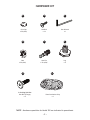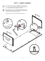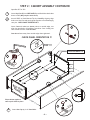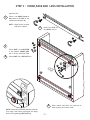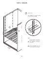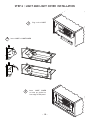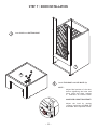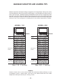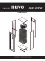
1
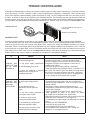
CELLAR
nuvo
k o o l s pac e
110/220
TM
ASSEMBLY & OPERATION MANUAL
READ BEFORE YOU START
1. LOCATING YOUR WINE CELLAR - Remember, it is not an appliance, it is a piece of furniture
A.
Provide 4” minimum clearance for both sides and back, keep the top completely clear.
Under no circumstances should the unit be “built-in” in any way.
B.
Never locate your wine cellar outdoors or in an area with extremes of temperature and
humidity.
Garages, attics, unfinished basements, laundry rooms, breezeways, closets, bedrooms or
any unventilated room. In other words these units must be installed in air-conditioned
environments which do not “trap” the warm air being exhausted.
C.
Temperatures in surrounding area must not exceed 80 °F (25 °C) with humidity levels not
to exceed 70% R.H. (Relative Humidity). Never set your temperatures below default (57ºF)
whenever ambient conditions are warm (above 75ºF) or humid (above 50%R.H.).
D.
Outlet power must be a DEDICATED separately fused, grounded, 15 Amp 110 - 120 V line or
7.5 Amp - 240 V line rated for your unit (CHECK BOX OR SERIAL NUMBER LABEL ON UNIT
FOR YOUR LINE VOLTAGE REQUIREMENTS).
E.
You must monitor your unit DAILY. If unit is in “Alarm”, unplug the unit inmediately. Always
check for any water (condensate) leaks.
Vintage Keeper will not be liable or responsible for incidental or consequential damages.
(See Warranty).
F.
Place unit in a clean area and allow access to the exterior surfaces for periodic vacuuming
of the condensor coil. (See troubleshooting for details.)
G.
Always remove all bottles before relocating your wine cellar.
2. AREA FOR ASSEMBLING YOUR WINE CELLAR
Choose a clear 12’ by 12’ area with a level floor and carpeting to help reduce scratching of surfaces.
3. TOOLS
*
*
*
*
Hex wrench (included)
Phillips screwdriver
Carpenter’s level
Helper or two is strongly recommended
4. TEST THE COOLING UNIT
Plug it in for a few minutes on a table top, to verify that controls and display are functional, and that
the unit is producing cool air after a few minutes of operation.
Note that the electronic controller has a one-minute cautionary delay between initial plug-in and
start-up of the compressor.
BEFORE YOU START !
NOTE: Fill out the WARRANTY REGISTRATION FORM with the serial number located on the LEFT
SIDE of unit.
~2~
HARDWARE KIT
A
B
C
Hex Bolt
x 14
Hex Wrench
x1
D
E
F
Cam
x 20 (x24)*
Cam Pin
x 20 (x24)*
Leg
x4
Cam Cap
x 20 (x24)*
H
G
In Cooling Unit Box
Hex Bolt (Flange)
x2
Panel Insulation Strip
x1
*NOTE : Hardware quantities for Model 220 are indicated in parenthesis.
~3~
STEP 1 : PANEL PREPARATION
CAUTION :
1. Watch for sharp staples on boxes.
2. DO NOT STEP ON PANELS
3. The manual will give a recommended
order to open boxes, it saves space and time.
H
PANEL EDGE
H
H
1
Open Box VP1.
!
1
Install INSULATION STRIP (H) to Back,
Top, and Bottom Panels. PUSH IN
FULLY!
2
Insert Cam Pins (E) by hand in BACK
PANEL’S predrilled holes down to
TAB.(May require some force)
H
CAUTION : DO NOT BREAK CAM PIN TABS!
DO NOT HAMMER!
TAB
TAB
BACK PANEL
E
~4~
STEP 2 : CABINET ASSEMBLY
1
Attach Top and Bottom to Back by CAREFULLY aligning edge holes
over Cam Pins and gently push together to avoid damaging cam
pins. DO NOT BANG OR SLAP PANELS TOGETHER!!!
2
Insert Cam, push all the way in under panel level (may require
some force) and make sure Arrow points to outside edge, use
allen key provided or #3 phillips screwdriver.
Cam Arrow faces away from outside edge when tightened
ME
TA
L
2
2
1
PANEL EDGE
CAM in LOCKED
POSITION
ME
TAL
BO
T
PA TO
NE M
L
����
~5~
STEP 2 : CABINET ASSEMBLY CONTINUED
Open Box VP5 or VP2.
1
2
Insert Cam Pins (E) into SIDE PANEL’S predrilled holes both sides
down to TAB. (May require some force)
Attach SIDES to Back/Bottom/Top by Carefully aligning edge
holes over Cam Pins and gently push together to avoid damaging
cam pins. CHECK PANEL ORIENTATION !!!
����
Insert Cam and make sure Arrow points to outside edge, use
allen key provided or #3 phillips screwdriver. Start locking one
cam at each end first. Lock all Cams.
1
Cam Arrow faces away from outside edge when tightened.
E
CHECK PANEL ORIENTATION !!!
TOP !!!
2 HOLES FOR MODEL 110
2
3 HOLES FOR MODEL 220
����
BO
T
PA TO
NE M
L
Place cabinet against a
wall to push sides in place.
A
3
3
Insert Cam Cap (A) in all Cam Holes.
~6~
��
��
STEP 3 : HINGE,BASE AND LEGS INSTALLATION
Open Box VP3.
1
Fasten one HINGE (found in
door box) to the SIDE of the
cabinet with Hexbolts (B).
F
NOTE : Hinge can be on either
side of the cabinet.
2
Install four LEGS (F)
into BASES fully in.
F
B
3
Fasten BASE to the BOTTOM
of the cabinet (FRONT BASE
has to be set with Base Tabs
4
3
FR
ON
TB
AS
E
Fasten BASE with HEX BOLTS (B)
1
CA
BO B I N
TT E T
OM
4
3
B
C
5
5
NOTE: Fasten base with base tab away from the
front edge, then fasten and adjust the hinge
before fully tightening HEX BOLTS (B)
~7~
Raise cabinet and check for potential air
leaks at panel joints from inside.
STEP 4 : SHELVES
1
Open box VP4
Hook SHELVES into hangers starting
from the bottom of cabinet
PRESS
1
TOP
1
2
BOTTOM
HINT :
CENTER SHELVES ON HANGERS
CA
BO B I N
TT E T
OM
~8~
1
Snap SHELVES into hangers
on one side
2
Push the SHELVES down to
snap into opposite side hangers
STEP 5 : COOLING UNIT INSTALLATION
1 GET HELP BEFORE INSTALLING AND KEEP CHILDREN CLEAR OF CELLAR CONSTRUCTION AREA.
Get helper to help guide unit, keep light cord clear of edge inside cellar and to prevent tipping of cellar. MAKE
SURE INSULATION STRIP IS IN CORRECT ORIENTATION. Run light cord through Cut-out. Slide unit into the back
opening by angling unit A to allow light cord to clear and straighten to push in B . Screw allen bolts (G) through
bottom flange holes. Make sure unit is level!
CHECK
DO NOT!!!
INSIDE CELLAR
INSULATION
STRIP
KEEP UNIT LEVEL
SHELF
LEVEL TO
OPENING
SIDE VIEW
STRAIGHTEN AND
PUSH THROUGH
B
GET HELPER TO
LIFT UNIT LEVEL
AND PULL FROM
INSIDE
A
G
CORD MUST
CLEAR OPENING
(G) x2 Flange
bolts in
cooling unit
box.
C
DO NOT OVER
TIGHTEN
NOTE: If unit is operated according to specifications overflows will not occur. Excess
condensation is only caused by extreme conditions. Unit will shut off at 72 °F and will
restart when temperature drops or unit is repluged. (In this case insert 3/8” O.D. hose
to drain hole, cut to appropriate length.)
Optional (not required)
except as emergency drain.
~9~
Container
STEP 6 : LIGHT AND LIGHT COVER INSTALLATION
1
2
Plug cord to LIGHT
Insert LIGHT to LIGHT COVER
3
Insert LIGHT COVER
to holes pre drilled on
front edge of TOP panel.
~ 10 ~
STEP 7 : DOOR INSTALLATION
1
Insert DOOR onto BOTTOM HINGE
1
C
2
B
2
Install TOP HINGE with HEX BOLTS (B)
NOTE :
Adjust final position of the door
before tightening the bolts and
move cellar into place, leaving
4” clearance all around cellar.
MAKE SURE CABINET IS AIRTIGHT!
Adjust the level by turning
(counter clockwise) the LEGS (F)
as needed. Use a carpenter’s level.
F
~ 11 ~
CONTROLS :
FEATURES:
-
OPERATION:
PLUG IT IN
(wait one minute)
and ENJOY!
Default SET temperature 57º F/14º C (ideal for wine storage).
DISPLAY:
Calibration option of the temperature sensor.
Display of actual temperature by request.
SET temperature range 52ºF-64ºF.
Digital temperature sensor.
Dual display Fº/Cº.
Settings are stored in memory for power failures.
Pre programed software will reach the quietest most efficient operation.
KEYS
57
- The display will show the detected temperature until the temperature will fall within 3º of the SET POINT.
- If the temperature is above the default 57º F + 1º or other preset value, after a delay of 1 minute the fan will
start, followed by the compressor within the next minute.
- The unit will cycle ON/OFF based on the temperature reading. Fan speeds are automatically set by the controller
to achieve optimum performance.
- Minimum ON and OFF cycle times are imposed by software, to prevent "short cycling".
CONTROLLER
OPERATION
TO DISPLAY:
BEFORE
AFTER
Actual temperature: PRESS
57º
56º
PRESS
70º
57º
57º
57º
SET temperature:
TO MODIFY SET
TEMPERATURE
(range is 52-64ºF):
DISPLAY EXAMPLE
ACTION
PRESS and RELEASE
To increase:
PRESS
once per degree
57º
58º
To decrease:
PRESS
once per degree
57º
56º
57º
14º
57º
57º
Wait 5 seconds
57º
F0
USE
F0
F1
F0
-1
The new value will be memorized and the controller will reset automatically.
TO CHAANGE FROM
ºF to ºC: or ºC to ºF
PRESS and HOLD
TO CALIBRATE:
PRESS and HOLD
until buzzer sounds in 5 seconds
The new value will be memorized and the controller will reset automatically.
while holding PRESS
or
for each degree of offset
and RELEASE
NOTE: A negative offset
will result in a warmer cabinet and a positive offset
will result in a cooler cabinet.
The new value will be memorized and the controller will reset automatically.
SAFETY FEATURES:
ALARM:
- If the temperature exceeds 72º F the unit will shut down, a sound warning will start and the dispaly will blink
alternating with the temperature reading.
- This function is disabled in the first 4 hours “ Cool Down” period or after any reset for another 4 hours.
- The unit will restart and continue the cooling and cycling if the temperature falls below 72º F.
TO RESET:
- Unplug and re plug the unit.
AL
MAXIMUM CAPACITIES AND LOADING TIPS
Maximum capacities and sample loading arrangements for Vintage Keeper Tuscany wine cellars
are illustrated below. Note the variations in shelf height, to accommodate the widest variety of
bottle types and sizes. Standard Burgundy and Bordeaux bottles are best arranged with necks
facing out; some taller bottles may need to be arranged neck to neck. Never stack bottles more
than two rows high on a shelf; all shelves must be installed as directed. Avoid placing bottles
directly in front of the cooling unit’s circulating fan for more uniform temperature in cabinet.
MODEL 110
13
Max 4" dia.
bottles
MODEL 220
WARNING*
7
Max 3.5" dia.
bottles
3 rows 3" dia.
or
2 rows 4.5" dia.
26
Max 4" dia.
bottles
14
7
14
7
14
7
14
7
14
7
7
Max 3.5" dia.
bottles
14
14
7
14
7
14
7
14
7
14
20
WARNING*
3 rows 3" dia.
or
2 rows 4.5" dia.
40
Max: 220 3" bottles
Max: 110 3" bottles
*WARNING:
Bottles in black will be in the cold air stream and could block airflow efficiency in some
circumstances (warm or humid areas). This area of the cabinet should have the coldest
temperature and may be used as your “chilling” section.
~ 13 ~
TROUBLE SHOOTING GUIDE
Although each Vintage Keeper cooling unit has been carefully tested at every stage of manufacture, occasional problems
arise, the majority of which are due to rough or careless handling during shipping or installation. Other problems may
derive from improper cabinet assembly, power interruption or surge, low line voltage (less than your unit rating of 105V
or 240V), or failure to clean the unit regularly (see illustration below). The following may help you determine what the
problem may be; what steps you can take to correct it, and what further steps may be required. Additional Trouble-Shooting information and downloadable documents are available in the “Support” area of our web site: www.koolspace.com
Cleaning the coil
Coil is located at the top of
back panel.
Vacuum it periodically
IMPORTANT NOTE:
In order to provide maximum protection for your valuable wine collection, the following steps are highly advisable.
First and foremost, have your wine collection adequately insured. Second, install a battery-powered heat-sensitive alarm
to warn of any loss of cooling due to power interruption. Third, monitor your storage and ambient conditions on a regular,
daily basis. Fourth, install a high quality surge suppressor to protect against sudden power fluctuations. Fifth, clean the
unit as directed, on a regular basis, every 3 to 4 months vacuum the cooling unit coils (check our website for more info).
Sixth make sure to check water level in the DRAIN CUP periodically and empty. Be advised, also, that Drobot-Vintage
Keeper cannot in any event be liable or responsible for incidental or consequential damages.
IF:
CHECK:
THEN:
- Is the unit plugged in?
- Note that the unit has a 1-minute cautionary delay
between plugging in and full start-up; this is a built-in
COOLING UNIT - Is the power supply operational? safeguard to protect the compressor in the event of
DOES NOT RUN
sudden power failure
AT ALL WHEN - Is the LED display functional?
- Note that the power supply must be a dedicated,
PLUGGED IN
separately-fused and grounded 15 Amp, 120V line or 7.5
- Is there any evidence of shipping Amp, 240 V line rated for your unit. Must not use an extendamage on the cooling unit or
sion cord. Do not share the outlet with other _appliances
packaging materials?
- If the unit is receiving power yet fans or compressor fail
to run, unplug for ten minutes, then try again
COOLING UNIT - Is the storage temp properly
RUNS BUT DOES set?
NOT COOL
SUFFICIENTLY
- Is the cabinet properly
assembled, with all joints air
tight?
- Note that the unit may take a few days to achieve the
desired storage temperature, even in a properly located,
airtight cabinet
- Take steps to reduce ambient temperatures and
compensate for additional heat gain if any cabinet walls
receive direct sunlight
- If gaps are visible at any panel joints, ensure that you
- Is the door properly adjusted to
have tightened all cams in all panels, to ensure
seal tightly when closed?
an airtight seal as detailed in our instructions
- Take steps to improve circulation of air to and from the unit
- Is airflow to and from the
- Adjust the door, if necessary, to seal tightly by
cooling unit unobstructed?
re-positioning the upper hinge and improving the cabinet
level
- Is the ambient air temperature
- Increase your SET TEMPERATURE
within the specified range?
- Clean the fan and grille areas
- If the problem persists, go to our website at
- Are any exterior surfaces of the
www.koolspace.com and perform the “cooling unit
cabinet exposed to sunlight?
diagnostic” in the support section.
CELLAR
nuvo
k o o l s pac e
Toll free: 1-888-274-8813
www.koolspace.com
110/220
TM