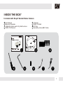
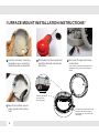
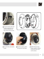
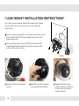
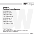
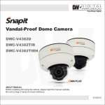
1
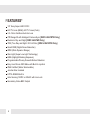
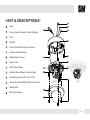
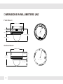
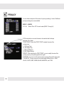
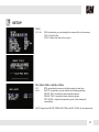
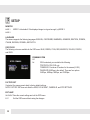
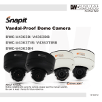
Vandal-Proof Dome Camera
DWC-V4367WD
DWC-V4367WTIR
ABOUT MANUAL
Before installing and using the camera, please read this manual carefully.
Be sure to keep it handy for future reference.
12132012
PRECAUTIONS
Do not open or modify.
Do not open the case except during maintenence and installation, for it may be dangerous and can
cause damages.
Do not put objects into the unit.
Keep metal objects and flammable substances from entering the camera.
It can cause fire, short-circuits, or other damages.
Be careful when handling the unit.
To prevent damages, do not drop the camera or subject it to shock or vibration.
Do not install near electric or magnetic fields.
Protect from humidity and dust.
Protect from high temperature.
Be careful when installing near the ceiling of kitchen or a boiler room, as the temperature may rise
to high levels.
Cleaning:
To remove dirt from the case, moisten a soft cloth with a soft detergent solution and wipe.
Mounting Surface:
The material of the mounting surface must be strong enough to support the camera.
FCC COMPLIANCE
This equipment has been tested and found to comply with the limits for a Class B digital device,
pursuant to part 15 of the FCC rules. These limits are designed to provide reasonable protection against
harmful interference, when the equipment is operated in a residential environment. This equipment
generates, uses, and radiates radio frequency energy; and if it is not installed and used in accordance
with the instruction manual, it may cause harmful interference to radio communications.
WARNING: Changes or modifications are not expressly approved by the manufacturer.
2
TABLE OF CONTENTS
Introduction
Installation
Features
4
Parts and Descriptions
5
Dimensions
6
Inside the Box
7
Mounting the Camera
Connecting to Monitors
Module OSD Menu
Troubleshooting
8-13
14-15
Adjusting the Camera Lens
16
Adjusting the 3-Axis Gimbal
17
18-29
30
Warranty Information
31-32
Specifications
33-34
3
FEATURES*
1/3” Sony Super HAD CCD II
620 TV Lines (B&W), 600 TV Lines (Color)
3.3~12mm Varifocal Auto Iris Lens
70ft Range IR with Intelligent Camera Sync [DWC-V4367WTIR Only]
Electronic Day and Night [DWC-V4367WD Only]
TDN (True Day and Night / IR Cut Filter) [DWC-V4367WTIR Only]
Smart DNR (Digital Noise Reduction)
WDR (Wide Dynamic Range)
Star-Light (Super Low Light Technology)
HME (Highlight Masking Exposure)
Programmable Privacy Zones & Motion Detection
Easy Icon Driven OSD Menu with Built-In Joystick
IP68 Certified (Water Submersible)
Junction Box Included
UTP & RS485 Built-In
Auto Sensing 12VDC or 24VAC with Line Lock
Secondary Video-BNC Output
4
PART & DESCRIPTIONS*
1
2
Lens
2
Power Input Connector (Dual Voltage)
3
UTP
4
RS-485
5
Primary Video-BNC Output Connector
6
Camera Control Board
7
Bubble Dome Cover
8
Upper Case
9
Flush Mount Base
10
Surface Mount Base / Junction Box
11
Assembly Screws (#8 - 32 x 0.75)
12
Secondary Video-BNC Output Connector
13
Safety Wire
14
Mounting Screws
3
5
4
10
14
13
9
6
12
1
NO IR
11
IR
8
7
5
DIMENSIONS IN MILLIMETERS (IN)*
Flush Mount
137(5.39”)
101(3.98”)
17(0.67”)
28(1.1”)
98.8(3.89”)
121
(4.76”)
54(2.13”)
Surface Mount
139(5.47”)
36(1.42”)
118.8
(4.68”)
29(1.41”)
53.8(2.12”)
6
121
(4.76”)
INSIDE THE BOX*
Included with Snapit Vandal Dome Camera
1
2
3
4
User Manual
Mounting Template
4 Machine Screw and 4 Dry Wall Anchors
TORX-T20 Wrench
5
6
7
8
L-Wrench
TORX-T20 Bolt
DC Plug
Secondary Video-BNC Cable
7
8
7
SURFACE MOUNT INSTALLATION INSTRUCTIONS*
Drill holes into the drywall and
insert the drywall mounts into
the holes.
4
Mount the surface mount
base (junction box) to the
wall.
8
Pull wires through and make
connections.
5
If you need to keep the wiring within the
camera housing, refer to the diagram
below.
5
UTP
RS48
DC 12V
AC 24V
Route wiring behind
the inner posts
(dark gray area).
3
RS48
2
UTP
Use the camera’s mounting
template or your camera to
mark the holes as required.
DC 12V
AC 24V
1
To use the side conduit, remove the
security screw with the supplied
3.0mm Allen key, and unscrew the
conduit plug.
5
Snap the camera module onto
the base by aligning the red
and black markings on the
base and the camera module.
6
Secure the three (3) assembly
screws.
7
Adjust the camera’s position
by using the 3-Axis Gimbal.
8
Tighten the three locking
screws in with the L-Wrench
to secure the dome cover
over the camera.
9
FLUSH MOUNT INSTALLATION INSTRUCTIONS*
For a flush mount housing, detach the surface mount base,
which is also known as the junction box, from the flush
mount base.
1
Use the mounting template to mark the holes for the screws
and a larger hole for the top extruded component of the
flush mount base.
2
The three assembly screws (ST4X35) fixed to the flush
mount base should be used to mount the camera to the
surface of the wall or ceiling.
ST4X35
3
Secure the three (3) assembly
screws.
10
4
Adjust the camera’s position
by using the 3-Axis Gimbal.
5
Tighten the three locking
screws in with the L-Wrench
to secure the cover dome
over the camera.
WALL MOUNT INSTALLATION INSTRUCTIONS*
1
Check to see all parts are in
the box.
2
Insert the wires from the
camera through the wall
mount housing.
3
Use the mounting template to
make pilot holes. Use the dry
wall anchors and woods screws
to attach the assembly.
4
Attach the camera’s surface
mount base (junction box) to
the wall mount.
5
Connect all cables and snap
the camera module onto the
base.
6
Adjust the camera and
secure the dome cover over
the camera module.
11
PENDANT MOUNT INSTALLATION INSTRUCTIONS*
1
Check to see all parts are in
the box.
2
Attach the top shield to the
pendant mount.
3
Run all necessary cables
from the ceiling to the mount.
4
Use the mounting template
to make pilot holes. Use the
dry wall anchors and wood
screws to attach the assembly
to the wall.
5
Connect all cables and verify
camera is operating properly.
6
Attach the camera to the
ceiling mount and secure the
dome cover properly.
12
CORNER MOUNT INSTALLATION INSTRUCTIONS*
1
Check to see all parts are in the box.
2
Attach the two compression fittings to the
corner bracket.
3
Attach the wall mount bracket to the corner
mount using the machine screws.
4
Mount the camera assembly to the corner of
the wall, using wall mount anchors and
machine screws.
13
CONNECTING TO MONITORS*
Use the diagram below to connect to a Monitor or CRT Monitor properly.
DC 12V / AC 24V
CCTV Monitor
IR
NO IR
300.0mm(11.8”)
Second Video Output
Monitor
Power Connection: 12VDC & 24VDC Dual Voltage (Auto Polarity Detection and Protection)
All cameras are equipped with a second video output for on-site configuration.
14
UTP SYSTEM*
Passive to Passive
Monitor
Passive UTP
UTP Cable (Max.300ft)
DVR(Digital Video Recorder)
Including the Passive UTP
Passive to Active
Monitor
Active UTP
UTP Cable (Max 3,000ft)
DVR(Digital Video Recorder)
Including the Passive UTP
15
ADJUSTING THE CAMERA LENS*
Follow the instructions provided below to make any lens adjustments.
Focus
Zoom
IR
1
2
3
4
ZOOM: TELE
FOCUS: FAR
-
WIDE
NEAR
NO IR
Loosen the zoom and focus handles by rotating them counter-clockwise.
Adjust the field of view by moving the handle RIGHT(TELE) to zoom in or LEFT(WIDE) to zoom out.
After the desired zoom position has been established, adjust the Focus the same way as described
above.
Once the desired adjustments have been made, tighten the handles back by turning them clockwise.
16
ADJUSTING THE 3-AXIS GIMBAL*
The Gimbal mechanism yields maximum rotation and placement as shown below.
NO IR
Rotation 360
NO IR
Tilting 90o
o
IR
NO IR
Panning 360
o
IR
IR
o
Tilting 75
17
MODULE OSD MENU*
EXPOSURE
COLOR
LENS
WB MODE
BACKLIGHT
OFF / BLC / HME / WDR
AGC
RED GAIN
0 ~ 255
BLUE GAIN
0 ~ 255
COLOR MODE
NORMAL / COOL / WARM
EXIT JUMP
MANUAL / DC
OFF / LOW / MID / HIGH / HIGHEST
STARLIGHT
OFF / x2 ~ x1024
3D DNR
OFF / LOW / MID / HIGH / SMART
EXIT JUMP
AWC / ATW / MANUAL / PUSHLOCK
DAY & NIGHT
D&N MODE
MIRROR / OFF
0 ~ 100
0 ~ 30
NIGHT C.
NIGHT A.
0 ~ 100
EXIT JUMP
SAVE & EXIT / EXIT
SAVE& EXIT / EXIT
PRIVACY
MASK 1
OFF / ON
MASK 2
OFF / ON
MASK 3
OFF / ON
MASK 4
EXIT JUMP
MASK 5
OFF / ON
MASK 6
OFF / ON
MASK 7
OFF / ON
MASK 8
OFF / ON
EXIT JUMP
SAVE & EXIT / EXIT
OFF / ON
SAVE& EXIT / EXIT
SLC
OFF / ON
NIGHT UP
EXIT JUMP
OFF / ON
SET-UP
TITLE EDIT
OFF / ON
DPC SET
OFF / AUTO
MONITOR
MODE 1 / MODE 2
LANGUAGE
ENGLISH / 繁體中文 / 简体中文 / 日本語 /
DEUTSCH / FRENCH / ITALIAN /
RUSSIAN / SPANISH / DUTCH
OSD COLOR
BLUE / GREEN / CYAN / RED /
MAGENTA / YELLOW / PURPLE /
GRAY
COMMUNICATION
OFF / ON
FACTORY SET.
NO / YES
EXIT JUMP
SAVE & EXIT / EXIT
18
SHARPNESS
GAMMA
MANUAL / 0.45 / 0.60 / 1.0
SAVE& EXIT / EXIT
AREA SET
AREA 1~4 > OFF / ON
SENSITIV.
1 ~ 30
SHOW INDI.
OFF / ICON / TRACE
EXTER-OUT.
OFF / ON
MIRROR
AUTO / COLOR / B&W
SAVE& EXIT / EXIT
MOTION
FUNCTION
EXIT
SAVE & EXIT
EXIT
EXPOSURE
LENS
Manual
DC
Manual mode supports the fixed board lens or the manual iris
lens.
DC mode supports the auto-iris varifocal lens.
NOTE: Both MANUAL and DC mode have FOCUS TARGET. You can adjust
the focus by finding the highest number on the FOCUS TARGET.
See page 16 for focus information.
ELC Levels and DC Levels are adjustable. The higher the number, the brighter
the image.
E. Shutter sets the shutter speed levels from 1/60 to 1/100000.
*For LENS-MANUAL Mode, the default E.SHUTTER is AUTO.
*For LENS-DC Mode, the default E.SHUTTER is 1/60. Select DC-AUTO for outdoor use.
Select 1/100FLC to run camera in flickerless mode.
Note: The STARLIGHT option cannot be controlled if the E.SHUTTER setting is
above 1/60.
19
EXPOSURE
BACKLIGHT
OFF
BLC
BACK LIGHT COMPENSATION
MANUAL
User can manually adjust the BLC level in five areas of the scene (TOP, BOTTOM, CENTER, LEFT, RIGHT).
Increase the BLC levels to make the image brighter.
SMART
This is recommended. Camera will automatically detect and adjust the BLC zone. BLC levels to choose
from include: LOWEST, LOW, MID, HIGH.
HME
HIGHLIGHT MASKING EXPOSURE
HME masks highlights to allow objects to appear clearly on the screen. If ON is selected, HME levels are
adjustable. The lower the number, the darker the masking areas.
WDR
(TRUE) WIDE DYNAMIC RANGE
True WDR in this camera is not supported by a double scan CCD. However, this special DSP can automatically
perform two scans depending on the lighting.
20
EXPOSURE
AGC (AUTO GAIN CONTROL)
OFF / LOW / MID / HIGH / HIGHEST
STARLIGHT
OFF / x2 ~ x1024
AGC enhances the picture brightness in low light conditions. A higher
level AGC setting makes the images brighter; however, it could increase
the amount of noise.
Starlight mode automatically activates slow shutter function when the
image is too dark. x4 is the default. We do not recommend you to
increase the setting, for it causes the image to lag.
Note: Starlight menu cannot be controlled if the E.SHUTTER setting is
above 1/60.
3D DNR (DIGITAL NOISE REDUCTION)
OFF / LOW / MID / HIGH / SMART
EXIT JUMP
SAVE & EXIT
EXIT
3D-DNR reduces the noise on the screen in low light conditions and
allows for clearer images, even at night. The SMART option will adjust
the camera to prevent lagging when there is motion.
Save the current settings and exit the OSD menu.
Exit the OSD menu without saving the changes.
21
COLOR
WB MODE
Auto White Balance Control mode compensates for color
temperature changes between 2000K and 18000K.
ATW
Auto Tracking White Balance Control mode compensates for color
temperature changes between 2500K and 9500K.
MANUAL
Users can control the white balance manually by changing RED
GAIN and BLUE GAIN (see below).
PUSHLOCK Pushlock is to fix the white balance based on the current lighting.
AWC
RED GAIN
0 ~ 255
Adjusts the amount of red in the image.
BLUE GAIN
0 ~ 255
Adjust the amount of blue in the image.
COLOR MODE
NORMAL
Color is similar to actual color.
COOL
Color has more blue.
WARM
Color has more red.
EXIT JUMP
SAVE & EXIT Save the current settings and exit the OSD menu.
EXIT
Exit the OSD menu without saving the changes.
22
DAY & NIGHT
D&N MODE
AUTO
Camera switches between day and night automatically depending
on light level. Camera will stay in color mode when there is enough
light. Camera will switch to B&W at night or other low light
environments.
*
COLOR
B&W
NIGHT C.
0 ~ 100
NIGHT A.
If AUTO is selected, please define the following settings:
*BURST: If ON is selected, the camera provides a color burst signal
in night mode. If OFF, no color burst signal is provided.
*COLOR->B&W: Adjusts the light level at which the camera switches from
*day (color) to night (B&W) mode. The higher the number, the lower the light level.
*B&W->COLOR: Adjusts the light level at which the camera switches from
*night (B&W) to day (color) mode. This number should be lower than the value
*of COLOR->B&W above.
*SMART IR: ON/OFF. If using IR LEDs, ON is recommended.
*READ TIME: Time interval delay before switching from day mode to night
*mode. It is adjustable from 3 seconds to 12 seconds.
*EX_IR INT.: AUTO/EXT. If using IR LEDs built into the camera, select AUTO.
*If using external IR LEDs separately, select EXT.
Camera always stays in day/color mode.
Camera always stays in night/B&W mode.
Color will be reduced in low light conditions.
(This level cannot be adjusted when 3D-DNR is ON.)
Edge sharpness will be reduced in low light conditions.
(This level cannot be adjusted when 3D-DNR is ON.)
EXIT JUMP
SAVE & EXIT Save the current settings and exit the OSD menu.
EXIT
Exit the OSD menu without saving the changes.
0 ~ 100
23
FUNCTION
MIRROR
OFF
MIRROR
Flips the image horizontally.
SHARPNESS
0 ~ 30
Sets the image sharpness. The higher the number, the sharper
the image.
GAMMA
0.45 / 0.60 / Select the desired gamma level. 0.45 is default setting.
1.0 / MANUAL
SLC (SIDE LIGHT COMPENSATION)
OFF / ON
Increase the brightness on sides of the image.
NIGHT-UP
OFF / ON
Adjusts sensitivity in low light conditions by set-up level. If ON is selected, the set-up level becomes higher,
and the images become brighter.
EXIT JUMP
SAVE & EXIT Save the current settings and exit the OSD menu.
EXIT
Exit the OSD menu without saving the changes.
24
MOTION
The camera can detect the movement and display an alarm on the screen
when movement is detected.
AREA SET
AREA 1 ~ 4
SENSITIV.
1 ~ 30
OFF / ON
If ON, motion areas can be selected and moved accordingly.
Select Areas 1-4 and adjust using controls for TOP, BOTTOM,
LEFT, or RIGHT.
Sensitivity level of the motion detection is adjustable. Motion
Detection will be more sensitive at a higher number.
SHOW INDI.
OFF / ICON Set the Show Indicator to OFF, ICON, or TRACE. If ICON is selected, a
TRACE
a bell will appear in the upper right hand corner when motion is
detected. If TRACE is selected, the area where motion was detected
will be highlighted.
EXTER OUT (ALARM SIGNAL, EXTERNAL OUTPUT)
OFF / ON
If ON is selected, you can set how long the alarm is displayed on
the screen when motion is detected (0 ~ 15 seconds).
EXIT JUMP
SAVE & EXIT Save the current settings and exit the OSD menu.
EXIT
Exit the OSD menu without saving the changes.
25
PRIVACY
You can hide some parts of the screen for privacy masking. A total of 8 different
privacy masking zones are available.
MASK 1 ~ MASK 8
OFF / ON
Select ON or OFF for each mask (MASK 1 through 8).
If ON is selected you can set the area to be masked and the shape
and color of the mask.
*START POINT: Select the START POINT to adjust the size of the
*privacy zone.
*L_TOP (Left Top)
*R_TOP (Right Top)
*L_BOT (Left Bottom)
*R_BOT (Right Bottom)
*MODIFY: After selecting the START POINT, you can modify the size of the
*privacy zone by moving the joystick left or right.
*POSITION: You can move the privacy zone by moving the joystick left or right.
*COLOR SET: Privacy zones can be set with eight different colors - GRAY,
*BLACK, WHITE, RED, GREEN, BLUE, MAGENTA, and CYAN.
26
SETUP
TITLE
OFF / ON
If ON is selected, you can display the camera title on the screen.
*CLR: Clear the title.
*POS: Position the title on the screen.
DPC (DEAD PIXEL CANCELLATION)
OFF
DPC automatically removes defective pixels in real time.
AUTO
If AUTO is selected, you can define the following settings:
*WHITE THR: Cancels the white defective pixels.
*BLACK THR: Cancels the black defective pixels.
*DPC LEVEL: Adjusts the sensitivity level of the dead pixel
*cancellation.
NOTE: Adjust the WHITE THR/BLACK THR and DPC LEVEL at the same time.
27
SETUP
MONITOR
MODE 1
MODE 2
MODE 1 is the default. If the displayed image is not good enough, try MODE 2.
LANGUAGE
The camera supports the following languages: ENGLISH, CANTONESE, MANDARIN, JAPANESE, DEUTSCH, FRENCH,
ITALIAN, RUSSIAN, SPANISH, AND DUTCH.
OSD COLOR
The following colors are available for the OSD menu: BLUE, GREEN, CYAN, RED, MAGENTA, YELLOW, PURPLE,
and GRAY.
COMMUNICATION
OFF
ON
If ON is selected, you can define the following:
*PROTOCOL: PELCO-D only.
*CAMERA ID: Provide an ID number for the camera (0~255).
*BAUDRATE: 9600bps is the default. There are four options:
*2400bps, 4800bps, 9600bps, and 19200bps.
FACTORY SET
If selected, the camera reverts back to factory default settings.
NOTE: FACTORY SET does not affect the LENS, DAY & NIGHT, CAMERA ID, and DPC SETTINGS.
EXIT JUMP
SAVE & EXIT Save the current settings and exit the OSD menu.
EXIT
Exit the OSD menu without saving the changes.
28
EXIT
EXIT
SAVE & EXIT Save the current settings and exit the OSD menu.
EXIT
Exit the OSD menu without saving the changes.
29
TROUBLESHOOTING
Before sending your camera for repair, check the following or contact our technical specialist.
FOR NO VIDEO
Check the coaxial cable and make sure it is connected securely.
Check the lens’ iris adjustment at the camera’s OSD menu.
Check the power supply and make sure the camera has the proper voltage and current.
FOR OUT-OF-FOCUS VIDEO
Check the clear dome cover and the lens for dirt or fingerprints. Use a soft cloth and gently clean.
Check the lens’ manual focal and zoom adjustment. The use of a field test monitor is recommended.
30
WARRANTY INFORMATION*
Digital Watchdog (referred to as “the Warrantor”) warrants the Digital Watchdog Camera against defects
in materials or workmanship as follows:
LABOR: For the initial five (5) years and one (1) year on IR LED from the original purchase date,
if the camera is determined to be defective, the Warrantor will repair or replace the unit with a new
or refurbished product at its option at no charge.
PARTS: In addition, the Warrantor will supply replacement parts for the initial five (5) years and
one (1) year on IR LED.
To obtain warranty or out of warranty service, please contact a Technical Support Representative at
1-866-446-3595 Monday through Friday from 8:30AM to 8:00PM Eastern Standard Time.
A purchase receipt or other proof of the original purchase date is required before warranty service
is rendered. This warranty only covers failures due to defects in materials and workmanship which
arise during normal use. This warranty does not cover damage which occurs in shipment or failures
which are caused by products not supplied by the Warrantor or failures which result from accident,
misuse, abuse, neglect, mishandling, misapplication, alteration, modification, faulty installation,
set-up adjustments, improper antenna, inadequate signal pickup, maladjustment of consumer
controls, improper operation, power line surge, improper voltage supply, lightning damage, rental
use of the product or service by anyone other than an authorized repair facility or damage that is
attributable to acts of God.
31
LIMITS AND EXCLUSIONS*
There are no express warranties except as listed. The warrantor will not be liable for incidental
or consequential damages (including damage to recording media without limitation) resulting
from the use of these products or arising out of any breach of the warranty. All express and
implied warranties, including the warranties of merchantability and fitness for particular purpose,
are limited to the applicable warranty period set forth above.
Some states do not allow the exclusion or limitation of incidental or consequential damages, or
limitatons on how long an implied warranty lasts, so the exclusions or limitations listed above
may not apply to you. This warranty gives you specific legal rights, and you may also have other
rights that vary from state-to-state.
If the problem is not handled to your satisfaction, then write to the following address:
Digital Watchdog, Inc.
ATTN: RMA Department
5436 W. Crenshaw Street
Tampa, FL 33634
Service calls which do not involve defective materials or workmanship as determined by the
Warrantor, in its sole discretion, are not covered. Costs of such service calls are the responsibility
of the purchaser.
32
SPECIFICATIONS*
VIDEO
Image Sensor
1/3" Sony Super HAD CCD II
Total Pixels
811 (H) x 508 (V), 411K Pixels
Effective Pixels
768 (H) x 494 (V)
Frequency
15.734KHz (H), 59.95Hz (V)
Synchronization
Internal or Line Lock
Horizontal Resolution
620 TV Lines [B&W], 600 TV Lines [Color]
Minimum Illumination
F1.2 (30IRE): 0.14 Lux [Color]
F1.2 (30IRE): 0.03 Lux [B&W]; 0.0 Lux [B&W] for IR Model
S/N Ratio
50dB (AGC off)
Video Output
CVBS: 1.0Vp-p / 75 Ω
LENS
Focal Length
3.3-12mm
Lens Type
DC Auto Iris
OPERATIONAL
Sharpness
0 ~ 30
Gamma
USER / 0.45 / 0.60 / 1.00
Star-Light
OFF / x2 ~ x1024
3D-DNR
OFF / LOW / MIDDLE / HIGH / SMART
33
OPERATIONAL
Back Light
OFF / BLC / HME / WDR
White Balance
AWC / ATW / MANUAL / PUSHLOCK
Privacy Zones
OFF / ON (8 Programmable Zones)
Language
ENGLISH / MANDARIN / CANTONESE / JAPANESE / GERMAN
FRENCH / ITALIAN / RUSSIAN / SPANISH / DUTCH
ENVIRONMENTAL
Operating Temperature
-29oC ~ 55oC (-20oF ~ 131oF)
Operating Humidity
Less than 90% (Non-Condensing)
Storage Temperature
-29oC ~ 70oC (-20oF ~ 158oF)
IP Rating
IP68 (Protects against dust and immersion beyond 3ft.)
ELECTRICAL
Power Requirement
Dual (12VDC & 24VAC)
Power Consumption
12VDC: 2.1W, 175mA / LED ON 4.5W, 375mA
24VAC: 2.2W, 91.7mA / LED ON 4.6W, 191.7mA
MECHANICAL
Housing Material
Aluminum
Dome Cover Material
Polycarbonate
Dimensions
∅139 X 118.8 mm (∅5.47 X 4.7 in)
Weight
2.028; 2.05 [IR Model]
*Specification is subject to change without prior notice.
34
MEMO*
35
5436 W Crenshaw St. Tampa, FL 33634
Tel : 866-446-3595 / 813-888-9555
Fax : 813-888-9262
www.Digital-Watchdog.com
[email protected]
Technical Support Hours : Monday-Friday
8:30am to 8:00pm EST