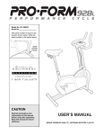
1
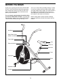
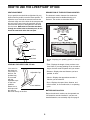
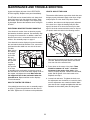
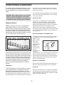
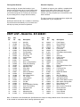
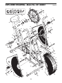
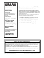
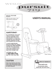
¨
Model No. 831.288261
Serial No.
_
Write the serial number in the space
above for future reference.
Serial
Number
Decal
Patent Pending
CAUTION
Read all precautions and instructions in this manual before using
this equipment. Keep this manual
for future reference.
USER'S MANUAL
SEARS, ROEBUCK AND CO., HOFFMAN ESTATES, IL 60179
TABLE OF CONTENTS
IMPORTANT PRECAUTIONS . . . . . . . . . . . . . . . . . . . . . . . . . . . . . . . . . . . . . . . . . . . . . . . . . . . . . . . . . . . . .2
BEFORE YOU BEGIN . . . . . . . . . . . . . . . . . . . . . . . . . . . . . . . . . . . . . . . . . . . . . . . . . . . . . . . . . . . . . . . . . . .3
ASSEMBLY . . . . . . . . . . . . . . . . . . . . . . . . . . . . . . . . . . . . . . . . . . . . . . . . . . . . . . . . . . . . . . . . . . . . . . . . . . .4
HOW TO USE THE LIFESTYLER¨ DT1000 . . . . . . . . . . . . . . . . . . . . . . . . . . . . . . . . . . . . . . . . . . . . . . . . . . .6
MAINTENANCE AND TROUBLE-SHOOTING . . . . . . . . . . . . . . . . . . . . . . . . . . . . . . . . . . . . . . . . . . . . . . . . .8
CONDITIONING GUIDELINES . . . . . . . . . . . . . . . . . . . . . . . . . . . . . . . . . . . . . . . . . . . . . . . . . . . . . . . . . . . . .9
PART LIST . . . . . . . . . . . . . . . . . . . . . . . . . . . . . . . . . . . . . . . . . . . . . . . . . . . . . . . . . . . . . . . . . . . . . . . . . . .10
EXPLODED DRAWING . . . . . . . . . . . . . . . . . . . . . . . . . . . . . . . . . . . . . . . . . . . . . . . . . . . . . . . . . . . . . . . . .11
ORDERING REPLACEMENT PARTS . . . . . . . . . . . . . . . . . . . . . . . . . . . . . . . . . . . . . . . . . . . . . . . .Back Cover
FULL 90 DAY WARRANTY . . . . . . . . . . . . . . . . . . . . . . . . . . . . . . . . . . . . . . . . . . . . . . . . . . . . . . .Back Cover
IMPORTANT PRECAUTIONS
WARNING: To reduce the risk of serious injury, read the following important precautions before
using the LIFESTYLER¨ DT1000.
1. It is the responsibility of the owner to ensure
that all users of the DT1000 are adequately
informed of all warnings and precautions.
9. When adjusting the seat, insert the seat knob
through one of the holes in the seat post (see
the drawing on page 3). Do not insert the seat
knob under the seat post.
2. Read all instructions in this manual before
using the DT1000. Use the DT1000 only as
described.
10. If you feel faint, dizzy, or short of breath while
exercising, stop immediately and begin
cooling down.
3. Place the DT1000 on a level surface. Cover
the floor beneath the DT1000 to protect the
floor or carpet.
11. The DT1000 is intended for home use only.
Do not use the DT1000 in any commercial,
rental, or institutional setting.
4. Inspect and tighten all parts regularly. Make
sure that the chain is properly adjusted (see
MAINTENANCE AND TROUBLE-SHOOTING
on page 8). Replace any worn parts immediately.
12. The decal shown below has been placed on
the DT1000. If the decal is missing, or if it is
not legible, please call our toll-free HELPLINE
to order a free replacement decal (see the
back cover of this manual). Apply the decal
in the location shown.
5. Keep children under age 12 and pets away
from the DT1000 at all times.
!
6. The DT1000 should not be used by
persons weighing more than 250 pounds.
Do not allow children on or
around machine.
Keep hands and feet away
from moving parts and contact
points.
7. Keep hands and feet away from the link arms
and other moving parts.
Read owner's manual and
follow instructions.
8. Do not wear loose clothing that could
become caught on the DT1000. Always
wear athletic shoes for foot protection.
WARNING: Before beginning this or any exercise program, consult your physician. This is especially
important for persons over the age of 35 or persons with pre-existing health problems. Read all
instructions before using. SEARS assumes no responsibility for personal injury or property damage
sustained by or through the use of this product.
2
BEFORE YOU BEGIN
Thank you for selecting the innovative LIFESTYLER¨
DT1000. The DT1000 blends advanced engineering
with contemporary styling to provide you with a lowimpact, total body workout in the convenience and
privacy of your own home.
until 7 p.m. Central Time (excluding holidays). To help
us assist you, please note the product model number
and serial number before calling. The model number is
831.288261. The serial number can be found on a
decal attached to the DT1000 (see the front cover of
this manual for the location of the decal).
For your benefit, read this manual carefully before
you use the LIFESTYLER¨ DT1000. If you have additional questions, please call our toll-free HELPLINE at
1-800-736-6879, Monday through Saturday, 7 a.m.
Before reading further, please review the drawing
below and familiarize yourself with the parts that are
labeled.
Handlebar
Water Bottle Holder
(Bottle not included)
Towel Holder
Seat
Electronic Monitor
Seat Post
Seat Knob
Frame
Side Shield
Pedal
Adjustable Cap
Link Arm
3
ASSEMBLY
Assembly requires two people. Place all parts of the LIFESTYLER¨ DT1000 in a cleared area and remove the
packing materials. Do not dispose of the packing materials until assembly is completed. Read through all steps
before beginning. During assembly, make sure that all parts are oriented as shown in the drawings.
Assembly requires the included tool and grease packet, an adjustable wrench
mallet
, and a phillips screwdriver
.
1. Insert the end of the Rear Stabilizer (34) into the Frame (46). Attach
the Rear Stabilizer to the Frame with four M5 x 12mm Screws (56).
, a rubber
1
56
34
46
2. Turn the Front Stabilizer (20) so the indented holes are facing the
floor. Attach the Front Stabilizer to the Frame (46) with two M8 x
48mm Carriage Bolts (57), two M8 Washers (43), and two
Acorn Nuts (12).
2
12
43
43
46
20
3. Remove the three 8mm Locknuts (36) from the underside of the Seat
(40). Attach the Seat to the top of the Seat Post (41) with the three
Locknuts.
3
40
Insert the Seat Post (41) into the Frame (46). Align one of the holes
in the Seat Post with the hole in the Frame. Insert the Seat Knob
(45) into the Frame and the Seat Post, and tighten the Seat Knob
into the Frame. Make sure to insert the Seat Knob through one of
the holes in the Seat Post; do not insert the Seat Knob under
the Seat Post.
41
45
36
36
46
4. Apply a small amount of grease to the Pivot Shaft (17). Slide the
Pivot Shaft into the Frame (46) and center it. Slide the Left
Handlebar (10) onto the left end of the Pivot Shaft. Slide the Right
Handlebar (not shown) onto the right end of the Pivot Shaft. Attach
an M8 Washer (43) and an 8mm Locknut (36) to each end of the
Pivot Shaft.
57
4
10
17
46
36
43
4
5. The Electronic Monitor (19) requires two ÒAAÓ batteries (not
included). Alkaline batteries are recommended. Locate the battery
compartment on the back of the Monitor. Insert two batteries into
the Monitor. Make sure that the negative ends of the batteries
(marked ÒÐÓ) are touching the springs in the Monitor. Close
the battery cover.
6. Thread the wire on the Electronic Monitor (19) through the hole in the
middle of the Monitor Bracket (61). Attach the Electronic Monitor (19)
to the Monitor Bracket with four Monitor Screws (59).
5
19
Batteries
6
19
Monitor
Wire
Connect the Sensor Wire (47) to the wire on the Electronic Monitor
(19). Attach the Monitor Bracket (61) to the Frame (46) using two M4
x 12.5mm Tek Screws (60). Make sure that the Sensor Wire is not
pinched between the Monitor and the Frame.
61
59
59
47
60
46
7. Apply a small amount of grease to the bolt welded in the Right
Handlebar (38). Connect a Link Arm (26) to the lower end of the
Right Handlebar with a Brass Handlebar Bushing (27), an M8
Washer (43), and an 8mm Locknut (36) as shown.
7
38
Attach the other Link Arm to the Left Handlebar in the same manner
(not shown).
26
27
36
43
8. Note: Apply a small amount of
8
grease to all of the small parts
assembled in this step. Slide a
11
24
23 26
32 23 33
39
13mm Washer (23) onto the
indicated end of a Pedal Axle
(24). Insert the Pedal Axle into
the right Link Arm (26). Slide a
Steel Link Arm Bushing (32), a
13mm Washer (23), and a
Pedal Spacer (33) onto the
Pedal Axle. Firmly tighten the Pedal Axle clockwise into the right arm of the Crank (39). Tighten a 1/2Ó
Locknut (22) onto the Pedal Axle.
Attach the other Pedal to the left arm of the Crank (not shown) in the same manner.
9. Make sure that all parts of the exercise bike are properly tightened.
5
22
HOW TO USE THE LIFESTYLER¨ DT1000
SEAT ADJUSTMENT
DESCRIPTION OF THE ELECTRONIC MONITOR
As you pedal, there should be a slight bend in your
knees when the pedals are at the lowest position. To
adjust the seat, first hold the seat and unscrew the
seat knob. Align one of the holes in the seat post with
the hole in the frame. Insert the seat knob into the
frame and the seat post, and tighten the seat knob
into the frame. Make sure to insert the seat knob
through one of the holes in the seat post; do not
insert the seat knob under the seat post.
The electronic monitor features five modes that
provide instant exercise feedback during your
workouts. The modes are described below.
Seat
Seat Post
Frame
Seat Knob
¥ SpeedÑDisplays your pedaling speed, in miles per
hour.
LEVELING THE LIFESTYLER¨ DT1000
If the exercise
bike does not
rest evenly on
the floor, the
problem may
be corrected
with the
adjustable caps
on the front
stabilizer.
Rotate one or
both caps until
the exercise
bike rests evenly on the floor.
¥ TimeÑDisplays the length of time you have exercised. Note: If you stop pedaling for ten seconds or
longer, the time mode will pause until you resume.
¥ DistanceÑDisplays the total distance you have
pedaled, in miles.
Adjustable Cap
¥ CalorieÑDisplays the approximate number of
Calories you have burned.
¥ ScanÑDisplays the speed, time, distance, and
calorie modes, for 5 seconds each, in a repeating
cycle.
Front Stabilizer
BATTERY INSTALLATION
Before the electronic monitor can be operated, two
ÒAAÓ batteries must be installed. If you have not
installed batteries, see assembly step 5 on page 5.
6
Speed, time, distance or calorie modeÑTo select
one of these modes for continuous display, press
the mode
button
repeatedly.
The mode
arrows will
show which
mode is
selected.
(Make sure
that the scan mode is not selected.)
HOW TO OPERATE THE ELECTRONIC MONITOR
1. To turn on the power, press the on/reset button or
simply begin pedaling. When the power is turned
on, the entire display will appear for two seconds.
The electronic monitor will then be ready for
operation.
2. Select one of the five modes:
Scan modeÑWhen the power is turned on, the
scan mode will automatically be selected. One
mode arrow
will show that
the scan mode
is selected,
and a flashing
mode arrow
will show
which mode is
currently
displayed. Note: If a different mode is selected, you
can select the scan mode again by repeatedly
pressing the mode button.
3. To reset the display, press the on/reset button.
4. To turn off the power, simply wait for about four
minutes. Note: The monitor has an Òauto-offÓ
feature. If the pedals are not moved and the
monitor buttons are not pressed for four
minutes, the power will turn off automatically
in order to conserve the batteries.
7
MAINTENANCE AND TROUBLE-SHOOTING
Inspect and tighten all parts of the LIFESTYLER¨
DT1000 regularly. Replace worn parts immediately.
HOW TO ADJUST THE CHAIN
The exercise bike features a precision chain that must
be kept properly lubricated. Apply a few drops of light
multi-purpose oil to the chain every three months.
The DT1000 can be cleaned with a soft, damp cloth.
Keep liquid away from the electronic monitor. Keep
the monitor out of direct sunlight or the display may
be damaged. Remove the batteries when storing the
DT1000.
In addition, the chain must be kept properly adjusted.
If the chain is too tight, the bearings may be damaged; if the chain is too loose, the fan may be damaged. If the chain causes excessive noise or slips as
you pedal, check the chain in the following manner:
ELECTRONIC MONITOR TROUBLE-SHOOTING
If the electronic monitor does not function properly,
the batteries should be replaced. See assembly step
5 on page 5 for instructions. In addition, make sure
that the sensor wire is connected to the wire on the
monitor. See assembly step 6 on page 5.
Fan
If the electronic monitor displays incorrect information,
the reed switch should be checked. First, remove the
pedal and the side shield from one side of the exercise bike.
Next, refer to
Reed
the drawing
Switch
at the right
and locate
the reed
switch. Turn
the sprocket
until the
magnet on
Magnet
Screw
the sprocket
is as close
as possible to the reed switch. Loosen the screw in
the reed switch, move the reed switch slightly closer to
the magnet, and tighten the screw. Make sure that
the magnet will not hit the reed switch when the
sprocket turns. Repeat until the monitor displays
correct information.
Axle Nut
Adjustment Nuts
1. Remove the fan guards from the front of the exercise bike. Remove the pedal and the side shield
from one side of the exercise bike.
2. Press down on the center of the chain. There
should be between 1/4Ó and 1Ó of vertical
movement in the center of the chain. If the
chain is properly adjusted, reattach the side shield,
pedal, and fan guards. If the chain needs to be
adjusted, see step 3.
3. Loosen both axle nuts. To tighten the chain, turn
the adjustment nuts clockwise; to loosen the chain,
turn the adjustment nuts counterclockwise. Make
sure that the fan is straight and tighten the axle nuts.
Reattach the side shield, pedal, and fan guards.
HOW TO TIGHTEN THE PEDALS
If the pedals become loose, refer to assembly step 8
on page 5. Tighten the pedal axles into the arms of
the crank. Tighten the 1/2" locknuts on the pedal axles.
8
CONDITIONING GUIDELINES
The following general guidelines will help you to plan
your exercise program. Remember that proper nutrition and adequate rest are essential for successful
results.
your goal is to burn fat, adjust your pace until your
heart rate is near the lowest number in your training
zone as you exercise.
For maximum fat burning, adjust your pace until your
heart rate is near the middle number in your training
zone as you exercise.
WARNING: Before beginning this or any exercise
program, consult your physician. This is especially important for individuals over the age of 35
or individuals with pre-existing health problems.
Aerobic Exercise
If your goal is to strengthen your cardiovascular
system, your exercise must be Òaerobic.Ó Aerobic
exercise is activity that requires large amounts of
oxygen for prolonged periods of time. This increases
the demand on the heart to pump blood to the
muscles, and on the lungs to oxygenate the blood.
For aerobic exercise, adjust your pace until your heart
rate is near the highest number in your training zone
as you exercise.
EXERCISE INTENSITY
Whether your goal is to burn fat or strengthen your
cardiovascular system, the key to achieving the
desired results is to exercise with the proper intensity.
The proper intensity level can be found by using your
heart rate as a guide. The chart below shows recommended heart rates for fat burning, maximum fat burning, and cardiovascular (aerobic) exercise.
HOW TO MEASURE YOUR HEART RATE
To measure your heart rate, first exercise for at least
four minutes. Then, stop exercising and place two
fingers on your
wrist as shown.
Take a sixsecond heartbeat count, and
multiply the
result by 10 to
find your heart
rate. For
example, if your
six-second
heartbeat count is 14, your heart rate is 140 beats per
minute. (A six-second count is used because your
heart rate will drop rapidly when you stop exercising.)
Adjust the intensity of your exercise until your heart
rate is at the desired level.
To find the proper heart rate for you, first find your age
near the top of the chart (ages are rounded off to the
nearest ten years). Next, find the three numbers below
your age. The three numbers are your Òtraining zone.Ó
The lowest number is the recommended heart rate for
fat burning; the middle number is the recommended
heart rate for maximum fat burning; the highest
number is the recommended heart rate for aerobic
exercise.
WORKOUT GUIDELINES
Each workout should include three important parts: a
warm-up, training zone exercise, and a cool-down.
Fat Burning
A Warm-up
To burn fat effectively, you must exercise at a relatively low intensity level for a sustained period of time.
During the first few minutes of exercise, your body
uses easily accessible carbohydrate calories for energy. Only after the first few minutes of exercise does
your body begin to use stored fat calories for energy. If
Start each workout with 5 to 10 minutes of stretching
and light exercise. A proper warm-up increases your
body temperature, heart rate, and circulation in preparation for strenuous exercise.
9
Training Zone Exercise
Exercise Frequency
After warming up, increase the intensity of your
exercise until your heart rate is in your training zone
for 20 to 30 minutes. (During the first few weeks of
your exercise program, do not keep your heart rate
in your training zone for longer than 20 minutes.)
To maintain or improve your condition, complete three
workouts each week, with at least one day of rest
between workouts. After a few months of regular
exercise, you may complete up to five workouts each
week if desired.
A Cool-down
The key to success is to make exercise a regular and
enjoyable part of your everyday life.
Finish each workout with 5 to 10 minutes of stretching.
This will increase the flexibility of your muscles and
will help to prevent post-exercise problems.
PART LISTÑModel No. 831.288261
Key
No.
Part
No.
Qty.
1
2
3
4
5
6
7
8
9
10
11
12
13
14
15
16
17
18
19
20
21
22
23
24
25
26
27
28
29
30
31
32
012105
115489
124757
115490
115483
104824
115484
040062
142453
142454
142455
012001
014073
142456
116030
142457
142458
112704
132827
142459
115488
142499
014101
142452
012150
142460
100364
103654
012006
014127
142461
101036
2
1
1
1
1
3
1
4
2
1
2
2
2
2
1
2
1
2
1
1
3
2
4
2
2
2
2
4
2
2
2
2
Description
Axle Nut
Fan Plate
Short Spacer
Fan Sprocket
Fan Axle Shaft
Flange Bushing
Fan Assembly
Handlebar Cap
Foam Grip
Left Handlebar
Pedal
Acorn Nut
8mm x 16mm Washer
Outer Pivot Bushing
Left Side Shield
Adjustable Cap
Pivot Shaft
Pedal Cap
Electronic Monitor
Front Stabilizer
M4 x 25mm Screw
1/2Ó Locknut
13mm Washer
Pedal Axle
Fan Nut
Link Arm
Brass Handlebar Bushing
Inner Pivot Bushing
Adjustment Nut
M6 Washer
Adjustment Bolt
Link Arm Bushing
R1097A
Key
No.
Part
No.
Qty.
33
34
35
36
37
38
39
40
41
42
43
44
45
46
47
48
49
50
51
52
53
54
55
56
57
58
59
60
61
62
#
#
109233
142462
120746
012002
115989
142463
117341
042043
142464
012042
014073
019288
142465
NSP
127201
100498
054035
107706
116038
025071
014041
008279
013088
142737
013002
123325
013141
102308
142657
117335
142242
139807
2
1
2
7
2
1
1
1
1
2
6
1
1
1
1
1
4
1
1
1
1
1
10
6
2
1
4
2
1
1
1
1
Description
Pedal Spacer
Rear Stabilizer
Stabilizer Cap
8mm Locknut
Fan Guard
Right Handlebar
Crank/Sprocket Assembly
Seat
Seat Post
Pedal Locknut
M8 Washer
Seat Post Bushing
Seat Knob
Frame
Reed Switch/Sensor Wire
Magnet
Fan Guard Clip
Long Spacer
Right Side Shield
Chain
M10 Flat Washer
Fan Guard Bracket
Self-tapping Screw
M5 x 12mm Washer Screw
M8 x 48mm Carriage Bolt
Reed Switch Screw
Monitor Screw
M4 x 12.5mm Tek Screw
Monitor Bracket
Crank/Sprocket
UserÕs Manual
Caution Decal
Note: Ò#Ó indicates a non-illustrated part. Specifications are subject to change without notice. See the back cover
of this manual for information about ordering replacement parts.
10
EXPLODED DRAWINGÑModel No. 831.288261
R1097A
50
6
25
53
Crank Assembly
39
8
9
7
18
2
42
21
4
6
10
40
3
25
11
13
6
24
15
9
44
23
23
14
32
43
36
8
33
17
38
36
61
14
36
45
56
43
36
60
41
19
56
1
28
47
28
5
22 46
35
47
28
58
59
26
31
52
36
8
48 22
34
55
62
29
30
33
35
32
43
29
30
23
27
49
37
24
8
54
23
26
12
43
27
11
55
36
51
56
42
16
20
55
1
16
13
18
43
55
57
11
49
The model number and serial number of your LIFESTYLER¨
DT1000 are listed on a decal attached to the frame. See the front
cover of this manual to find the location of the decal.
Model No. 831.288261
QUESTIONS?
If you find that:
¥ you need help assembling or
operating the LIFESTYLER¨
DT1000
All replacement parts are available for immediate purchase or
special order when you visit your nearest SEARS Service Center.
To request service or to order parts by telephone, call the toll-free
numbers listed at the left.
When requesting help or service, or ordering parts, please be
prepared to provide the following information:
¥ a part is missing
¥ The NAME OF THE PRODUCT (LIFESTYLER¨ DT1000)
¥ or you need to schedule repair
service
call our toll-free HELPLINE
1-800-736-6879
MondayÐSaturday, 7 amÐ7 pm
Central Time (excluding holidays)
¥ The MODEL NUMBER OF THE PRODUCT (831.288261)
¥ The PART NUMBER OF THE PART (see page 10)
¥ The DESCRIPTION OF THE PART (see page 10)
REPLACEMENT
PARTS
If parts become worn and need to
be replaced, call the following
toll-free number
1-800-FON-PART
(1-800-366-7278)
FULL 90 DAY WARRANTY
For 90 days from the date of purchase, if failure occurs due to defect in material or workmanship in this
SEARS BIKE EXERCISER, contact the nearest SEARS Service Center throughout the United States
and SEARS will repair or replace the BIKE EXERCISER, free of charge.
This warranty does not apply when the BIKE EXERCISER is used commercially or for rental purposes.
This warranty gives you specific legal rights, and you may also have other rights which vary from state
to state.
SEARS, ROEBUCK AND CO., DEPT. 817WA, HOFFMAN ESTATES, IL 60179
Part No. 142242 G03569-C R1097A
Printed in China © 1997 Sears, Roebuck and Co.