1
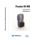
Spyder3
S3-14 and S3-24
Camera Link Dual Line Scan Mono Camera
User’s Manual
Feb 23 2012
03-032-20117-00
www.teledynedalsa.com
S3-14-01k40-00-R
S3-14-02k40-00-R
S3-24-01k40-00-R
S3-24-02k40-00-R
S3-24-04k40-00-R
2
Spyder3 S3-14 and S3-24 User's Manual
© 2012 Teled yne DALSA. All inform ation provid ed in this m anual is believed to be accurate and reliable. N o responsibility is
assum ed by Teled yne DALSA for its use. Teled yne DALSA reserves the right to m ake changes to this inform ation w ithout notice.
Reprod uction of this m anual in w hole or in part, by any m eans, is prohibited w ithout prior perm ission h aving been obtained from
Teled yne DALSA.
About Teledyne Technologies and Teledyne DALSA, Inc.
Teled yne Technologies is a lead ing provid er of sophisticated electronic subsystem s, instrum entation and com m unication prod uct s,
engineered system s, aerospace engines, and energy and pow er generation system s. Teled yne Technologies’ operations are
prim arily located in the United States, the United Kingd om and Mexico. For m ore inform ation, visit Teled yne Technologies’
w ebsite at w w w .teled yne.com .
Teled yne DALSA, a Teled yne Technologies com pany, is an international lead er in high perform ance d igital im aging and
sem icond uctors w ith approxim ately 1,000 em ployees w orld w id e, head quartered in Waterloo, Ontario, Canad a. Established in
1980, the com pany d esigns, d evelops, m anu factures and m arkets d igital im aging prod ucts and solutions, in ad d ition to provid ing
MEMS prod ucts and services. For m ore inform ation, visit Teled yne DALSA’s w ebsite at w w w .teled yned alsa.com .
Support
For further inform ation not includ ed in this m anual, or for inform ation on Teled yne DALSA’s extensive line of im age sensing
prod ucts, please contact:
North America
Europe
Asia Pacific
605 McMurray Rd
Waterloo, ON N 2V 2E9
Canad a
Breslauer Str. 34
Ikebukuro East 13F
D-82194 Gröbenzell (Munich)
3-4-3 H igashi-Ikebukuro
Germ any
Toshim a-ku, Tokyo 170-0013
Tel: 519 886 6000
Fax: 519 886 8023
Tel: +49 - 8142 – 46770
Japan
Fax: +49 - 8142 – 467746
Tel: 81 3 5960 6353
w w w . teled yned alsa.com
Fax: 81 3 5960 6354 (fax)
sales.europe@teled yned alsa.com
support@teled yned alsa.com
w w w .teled yned alsa.com
w w w .teled yned alsa.com
sales.am ericas@teled yned alsa.com
support@teled yned alsa.com
sales.asia@teled yned alsa.com
support@teled yned alsa.com
Industry Standards
Teled yne DALSA and this m od el of the Spyd er3 cam era support the Cam era Link™ com m unications interface for vision
applications. Cam era Link is a high speed com m unications interface for vision applications. It provid es a stand ard m ethod of
com m unication betw een d igital cam eras and fram e grabbers.
Detailed inform ation on Cam era Link is available in the Teled yne DALSA Cam era Link Im plem entation Road Map d ocum entation,
available from the Know led ge Center on our Web site: (http:/ / w w w .teled yned alsa.com / m v/ know led ge/ appnotes.aspx).
03-032-20117-00
Teledyne DALSA
Spyder3 S3-14 and S3-24 User's Manual
3
Contents
SYSTEM PRECAUTIONS AND CLEANING .................................................................................................................................. 5
THE SPYDER3 S3-14 AND S3-24 CAMERAS.............................................................................................................................. 7
CAMERA HIGHLIGHTS ..............................................................................................................................................................................................................7
CAMERA PERFORMANCE SPECIFICATIONS ....................................................................................................................................................................................8
CERTIFICATIONS....................................................................................................................................................................................................................10
RESPONSIVITY ......................................................................................................................................................................................................................10
DERATING CURVES................................................................................................................................................................................................................12
MECHANICALS ......................................................................................................................................................................................................................14
IMAGE SENSOR .....................................................................................................................................................................................................................16
SOFTWARE AND HARDWARE SETUP .........................................................................................................................................................................................17
SETUP STEPS: OVERVIEW ......................................................................................................................................................................................................17
STEP 1. INSTALL AND CONFIGURE THE FRAME GRABBER AND GRAPHICS CARD ................................................................................................................................18
STEP 2. CONNECT POWER AND CAMERA LINK CABLES ................................................................................................................................................................18
INPUT SIGNALS, CAMERA LINK ...............................................................................................................................................................................................22
CAMERA LINK VIDEO TIMING ..................................................................................................................................................................................................23
STEP 3. ESTABLISH COMMUNICATION WITH THE CAMERA ............................................................................................................................................................26
USING CAMERA LINK WITH SPYDER3 CAMERAS .........................................................................................................................................................................27
CAMERA OPERATION ............................................................................................................................................................ 29
FACTORY SETTINGS ...............................................................................................................................................................................................................29
RETURNING CAMERA SETTINGS ...............................................................................................................................................................................................29
SAVING AND RESTORING SETTINGS .........................................................................................................................................................................................32
CAMERA OUTPUT FORMAT .....................................................................................................................................................................................................33
EXPOSURE MODE, LINE RATE AND EXPOSURE TIME ...................................................................................................................................................................39
EXPOSURE MODES IN DETAIL .................................................................................................................................................................................................40
SENSOR OUTPUT FORMAT......................................................................................................................................................................................................44
DATA PROCESSING................................................................................................................................................................................................................47
ANALOG AND DIGITAL SIGNAL PROCESSING CHAIN ...................................................................................................................................................................48
RETURNING CALIBRATION RESULTS AND ERRORS ......................................................................................................................................................................59
END-OF-LINE SEQUENCE .......................................................................................................................................................................................................60
SETTING THRESHOLDS...........................................................................................................................................................................................................61
LOOK-UP TABLES .................................................................................................................................................................................................................62
SAVING AND RESTORING PRNU AND FPN COEFFICIENTS...........................................................................................................................................................63
DIAGNOSTICS .......................................................................................................................................................................................................................65
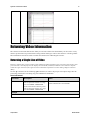
RETURNING VIDEO INFORMATION ...........................................................................................................................................................................................67
RETURNING AVERAGED LINES OF VIDEO ..................................................................................................................................................................................68
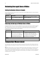
TEMPERATURE MEASUREMENT ................................................................................................................................................................................................68
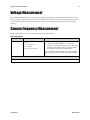
VOLTAGE MEASUREMENT .......................................................................................................................................................................................................69
CAMERA FREQUENCY MEASUREMENT .......................................................................................................................................................................................69
ASCII COMMANDS: REFERENCE ..............................................................................................................................................................................................70
ERROR HANDLING ................................................................................................................................................................................................................76
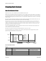
CLEARING DARK CURRENT .....................................................................................................................................................................................................77
APPENDIX B .......................................................................................................................................................................... 85
CAMERA LINK REFERENCE, TIMING, AND CONFIGURATION TABLE .................................................................................................................................................85
CAMERA LINK BIT DEFINITIONS ..............................................................................................................................................................................................87
CAMERA LINK CONFIGURATION TABLES ....................................................................................................................................................................................87
Teledyne DALSA
03-032-20117-00
4
Spyder3 S3-14 and S3-24 User's Manual
APPENDIX C .......................................................................................................................................................................... 92
EMC DECLARATION OF CONFORMITY .......................................................................................................................................................................................92
REVISION HISTORY ............................................................................................................................................................... 93
INDEX ................................................................................................................................................................................... 94
03-032-20117-00
Teledyne DALSA
Spyder3 S3-14 and S3-24 User's Manual
5
System Precautions and
Cleaning
Precautions
Read these p recau tions and this m anu al carefu lly before u sing the cam era.
Confirm that the cam era’s p ackaging is u nd am aged before op ening it. If the p ackaging is d am aged p lease
contact the related logistics p ersonnel.
Do not op en the hou sing of the cam era. The w arranty is void ed if the hou sing is op ened .
Keep the cam era hou sing tem p eratu re in a range of 0 °C to 65 °C d u ring op eration.
Do not op erate the cam era in the vicinity of strong electrom agnetic field s. In ad d ition, avoid electrostatic
charging, violent vibration, and excess m oistu re.
To clean the d evice, avoid electrostatic charging by u sing a d ry, clean absorb ent cotton cloth d am p ened
w ith a sm all qu antity of p u re alcohol. Do not u se m ethylated alcohol. To clean the su rface of the cam era
hou sing, u se a soft, d ry cloth. To rem ove severe stains u se a soft cloth d am p ened w ith a sm all qu antity of
neu tral d etergent and then w ip e d ry. Do not u se volatile solvents su ch as benzene and thinners, as they
can d am age the su rface finish. Fu rther cleaning instru ctions are below .
This cam era d oes not su p p ort hot p lu gging. Pow er d ow n and d isconnect p ow er to the cam era before you
ad d or rep lace system com p onents.
Electrostatic Discharge and the CMOS Sensor
Im age sensors and the cam era bod ies hou sing are su scep tible to d am age from electrostatic d ischarge
(ESD). Electrostatic charge introd u ced to the sensor w ind ow su rface can ind u ce charge bu ild u p on the
u nd ersid e of the w ind ow that cannot be read ily d issip ated by the d ry nitrogen gas in the sensor p ackage
cavity. The charge norm ally d issip ates w ithin 24 hou rs and the sensor retu rns to norm al op eration.
Protecting Against Dust, Oil, and Scratches
The sensor w ind ow is p art of the op tical p ath and shou ld be hand led like other op tical com p onents, w ith
extrem e care. Du st can obscu re p ixels, p rod u cing d ark p atches on the sensor resp onse. Du st is m ost
visible w hen the illu m ination is collim ated . The d ark p atches shift p osition as the angle of illu m ination
changes. Du st is norm ally not visible w hen the sensor is p ositioned at the exit p ort of an integrating
sp here, w here the illu m ination is d iffu se. Du st can norm ally be rem oved by blow ing t he w ind ow su rface
u sing an ionized air gu n. Oil is u su ally introd u ced d u ring hand ling. Tou ching the su rface of the w ind ow
barehand ed w ill leave oily resid u es. Using ru bber fingercots and ru bber gloves can p revent
contam ination. H ow ever, the friction betw een ru bber and the w ind ow m ay p rod u ce electrostatic charge
that m ay d am age the sensor. To avoid ESD d am age and to avoid introd u cing oily resid u es, avoid
Teledyne DALSA
03-032-20117-00
6
Spyder3 S3-14 and S3-24 User's Manual
tou ching the sensor. Scratches d iffract incid ent illu m ination. When exp osed to u niform illu m ination, a
sensor w ith a scratched w ind ow w ill norm ally have brighter p ixels ad jacent to d arker p ixels. The location
of these p ixels w ill change w ith the angle of illu m ination.
Cleaning the Sensor Window
Recommended Equipment
Glass cleaning station w ith m icroscop e w ithin clean room .
3M ionized air gu n 980 (http :/ / solu tions.3m canad a.ca/ w p s/ p ortal/ 3M/ en_CA/ WW2/ Cou ntry/ )
Ionized air flood system , foot op erated .
Sw ab (H UBY-340CA-003) (http :/ / w w w .cleancross.net/ m od u les/ xfsection/ article.p hp ?articleid =24)
Single d rop bottle (FD-2-ESD)
E2 (Eclip se op tic cleaning system (w w w .p hotosol.com )
Procedure
Use localized ionized air flow on to the glass d u ring sensor cleaning.
Blow off m obile contam ination u sing an ionized air gu n.
Place the sensor u nd er the m icroscop e at a m agnification of 5x to d eterm ine t he location of any
rem aining contam ination.
Clean the contam ination on the sensor u sing one d rop of E2 on a sw ab.
Wip e the sw ab from left to right (or right to left bu t only in one d irection). Do this in an overlap p ing
p attern, tu rning the sw ab after the first w ip e and w ith each su bsequ ent w ip e. Avoid sw ip ing back
and forth w ith the sam e sw ab in ord er to ensu re that p articles are rem oved and not sim p ly
transferred to a new location on the sensor w ind ow . This p roced u re requ ires you to u se m u ltip le
sw abs.
Discard the sw ab after both sid es of the sw ab have been u sed once.
Rep eat u ntil there is no visible contam ination p resent
03-032-20117-00
Teledyne DALSA
Spyder3 S3-14 and S3-24 User's Manual
7
The Spyder3 S3-14 and S3-24
Cameras
Camera Highlights
The Sp yd er3 CL su rp asses its p red ecessor, the Sp yd er2, w ith 3x m ore resp onsivity a nd 2x the sp eed . At
its core is d u al line scan technology that achieves u np reced ented resp onsivity and throu ghp u t rates of 80
m egap ixels p er second , w ithou t im p acting noise.
The Sp yd er3 CL featu res the Cam era Link™ serial interface and is fu lly p rogram m able, offering p recise
control over key p erform ance variables su ch as gain and offset and im p roved ease of u se and setu p .
The tem p eratu re range p erform ance of the SC-14 and SC-24 m od els has increased from an op erating
tem p eratu re of 0 °C to 50 °C to an op erating tem p eratu re of 0 °C to 65 °C.
Features and Programmability
Broad band resp onsivity u p to 408 ±16 DN (nJ/ cm 2) @10 d B gain, 8 bit
1024, 2048, or 4096 p ixels, 14 µm x 14 µm (1k and 2k) and 10 µm x 10 µm (4k) p ixel p itch, 100% fill
factor
Up to 68 kH z line rates
Dynam ic range u p to 1400:1
Data transm ission exceed ing 10 m eters
±50 µm x, y sensor alignm ent
Base Cam era Link configu ration (8 or 12 bit d ata on 1 or 2 tap s d ep end ing on cam e ra m od el)
Serial interface (ASCII, 9600 bau d , ad ju stable to 19200, 57600, 115200), throu gh Cam era Link .
Mirroring and forw ard / reverse control.
Program m able gain, offset, exp osu re tim e and line rate, trigger m od e, test p attern ou tp u t, and
cam era d iagnostics.
Tall p ixel, high sensitivity, or low sensitivity m od e available.
Flat-field correction—m inim izes lens vignetting, non -u niform lighting, and sensor FPN and PRN U.
Applications
FPD insp ection
Pick and p lace
Container insp ection
Wood / tile / steel insp ection
100% p rint insp ection (lottery tickets, stam p s, bank notes, p aychecks)
Postal sorting
Glass bottle insp ection
Ind u strial m etrology
Food insp ection
Web insp ection
Teledyne DALSA
03-032-20117-00
8
Spyder3 S3-14 and S3-24 User's Manual
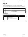
Models
The Sp yd er3 CL cam era is available in these m od els.
Table 1: Spyder3 CL Camera Models Overview
Model Number
Description
S3-24-01K40-00-R
1k resolution, 2 sensor taps. Base Cam era Link configuration .
S3-24-02K40-00-R
2k resolution, 2 sensor taps. Base Cam era Link configuration .
S3-14-01K40-00-R
1k resolution, 1 sensor tap . Base Cam era Link configuration .
S3-14-02K40-00-R
2k resolution, 1 sensor tap . Base Cam era Link configuration .
S3-24-04k40-00-R
4k resolution, 2 sensor taps. Base Cam era Link configuration.
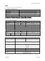
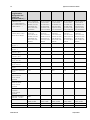
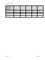
Camera Performance Specifications
Table 2: Camera Performance Specifications
Feature / Specification
1k
2k
4k
Im ager Form at
d ual line scan
Resolution
1024 pixels
2048 pixels
4096 pixels
Pixel Fill Factor
100 %
Pixel Size
14 µm x 14 µm
10 µm x 10 µm
Sensitivity Mod e
H igh, low , or tall pixel
Antibloom ing
100 x
Gain Range
± 10 d B
Speed
1k
Data Rate
40 m p / s and 80 m p / s
Maxim um Line
Rate
2k
4k
80 m p / s
2 tap m od el
68 kH z (80 MH z)
36 kH z (80 MH z)
18.5 kH z
1 tap m od el
36 kH z (40 MH z)
18.5 kH z (40 MH z)
NA
Optical Interface
Lens Mount
1k and 2k
4k
M42 x 1, C and F*
M58 x 0.75, F*
Focal Length
6.56 m m ± 0.25
Sensor Alignm ent
Mechanical Interface
Cam era Size
Mass
Connectors
03-032-20117-00
x ± 50 µm
y ± 50 µm
z ± 0.25 m m
z ± 0.2 º
1k and 2k
4k
72 m m (h) x 60 m m (l) x 60 m m (w )
60 m m (h) x 72 m m (l) x 60 m m (w )
< 300 g
6 pin m ale H irose pow er
MDR26 fem ale d ata connector
Teledyne DALSA
Spyder3 S3-14 and S3-24 User's Manual
9
Electrical Interface
1k and 2k
Input Voltage
4k
+ 12 to +15 Volts DC
Pow er Dissipation
< 5 W (1k and 2k)
Operating Tem perature
< 7 W (4k)
0 ºC to 65 ºC
Bit Wid th
8 or 12 bits user selectable
Output Data Configuration
Base Cam era Link
*Lens m ount ad apters are available. Contact Teled yne DALSA Sales for m ore inform ation.
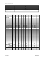
Table 3: Camera Operating Specifications
Specifications
Unit
Min
Broadband
responsivity
-10dB
Typ
Max
Min
0dB
Typ
Max
Min
+10dB
Typ
Max
DN /
(nJ/cm²)
1k and 2k Dual line
652.8
2064
6528
1k and 2k Single line
326.4
992
3264
4k Dual line
431
1363
4310
4k Single line
216
682
2155
Random noise rms
DN
Dynamic range
DN : DN
3
6.5
9.2
20.5
30
65
1k and 2k Dual line
500:1
1400:1
203:1
324:1
59:1
108:1
1k and 2k Single line
500:1
1400:1
203:1
324:1
59:1
108:1
4k Dual and Single
FPN global
1225:1
387:1
122.3:1
DN p-p
Uncorrected
Corrected
52.8
169.6
536
32
32
64
PRNU ECD
Uncorrected local
%
8.5
8.5
11.5
Uncorrected global
%
10
10
10
Corrected local
DN p-p
80
80
95
Corrected global
DN p-p
80
80
95
Uncorrected local
%
8.5
12
37
Uncorrected global
%
10
12
37
Corrected local
DN p-p
80
237
752
Corrected global
DN p-p
80
208
752
PRNU ECE
SEE (calculated)
nJ / cm²
Dual line
6.35
1.92
0.61
Single line
12.2
4.0
1.2
4.6
4.5
4.6
9.2
9.3
9.2
NEE (calculated)
pJ / cm²
Dual line
Single line
Saturation output
amplitude
DN
DC offset
DN
Teledyne DALSA
3968
±80
96
160
336
03-032-20117-00
10
Spyder3 S3-14 and S3-24 User's Manual
Test conditions unless otherwise noted
12-bit valu es, Flat Field Correction (FFC) enabled .
CCD Pixel Rate: 40 m egap ixels/ second p er sensor tap .
Line Rate: 5000 H z.
N om inal Gain setting u nless otherw ise sp ecified .
Light Sou rce: Broad band Qu artz H alogen, 3250k, w ith 750 nm high p ass filter installed .
Am bient test tem p eratu re 25 °C.
Unless sp ecified , all valu es are referenced at 12 bit.
Exp osu re m od e d isabled .
Unless sp ecified , d u al line m od e.
Notes
1.
PRN U m easu red at 50% SAT.
Certifications
Table 4: EMC Compliance Standards
Compliance
The CE Mark, FCC Part 15, and Ind ustry Canad a ICES-003 Evaluation of the DALSA Spyd er3 CL S3-14and S3-24
cam eras m eet the follow ing requirem ents:
CISPR 22, EN 55022 and EN 61326 Class A Em issions Requirem ents, EN 55024, and EN 61326 Im m unity to
Disturbances
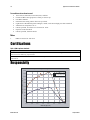
Responsivity
Spectral Responsivity. Nominal Gain
2500
High Sensitivity Mode
2250
Low Sensitivity Mode
Responsivity {DN/(nJ/cm²)}
2000
1750
1500
1250
1000
750
500
250
0
400
500
600
700
800
900
1000
1100
Wavelength (nm)
03-032-20117-00
Teledyne DALSA
Spyder3 S3-14 and S3-24 User's Manual
11
Figure 1: Spyder3 CL 1k and 2k Responsivity
Spectral Responsivity. Nominal Gain
100
High Sensitivity Responsivity
90
Low Sensitivity Responsivity
Responsivity {DN/(uJ/cm²)}
80
70
60
50
40
30
20
10
0
400
500
600
700
800
900
1000
1100
Wavelength (nm)
Figure 2: Spyder3 CL 4k Responsivity
Teledyne DALSA
03-032-20117-00
12
Spyder3 S3-14 and S3-24 User's Manual
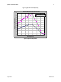
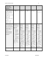
Derating Curves
Figure 3: 1k and 2k Derating Curves
03-032-20117-00
Teledyne DALSA
Spyder3 S3-14 and S3-24 User's Manual
13
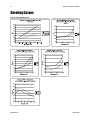
Figure 4: 4k Derating Curves
Changes in DC offset with Integration Time
(12bit, 0dB, HSM, 4K model)
4K model: Change in DC Offset vs Temperature
(12bit, Integration Time 200us)
200.000
140
180.000
120
160.000
100
140.000
DN
DN
80
120.000
+10dB HSM
100.000
+10dB LSM
60
80.000
40
60.000
-10dB LSM
40.000
20
20.000
0.000
0
3.3
2.0
1.0
0.5
0.3
0.2
0.1
0C
0.1
10C
20C
30C
40C
50C
60C
Temperature (Celsius)
Integration Time (ms)
4K model: Change in FPN vs. Temperature
(12bit, 0dB Gain, Integration Time 100us )
4K model: Change in Noise vs. Temperature
(12bit, 0dB Gain, Integration time 100us)
30.000
9.400
9.200
25.000
9.000
20.000
8.600
HSM
8.400
DN
DN(rms)
8.800
HSM
15.000
LSM
LSM
8.200
10.000
8.000
5.000
7.800
7.600
0.000
0C
7.400
0C
10C
20C
30C
40C
50C
60C
10C
20C
30C
40C
50C
60C
Temperature
Temperature (Celcius)
4K model: Change in PRNU vs. Temperature
(12bit, 0dB, Integration Time 100us)
80.000
70.000
60.000
DN
50.000
LSM
40.000
HSM
30.000
20.000
10.000
0.000
0C
10C
20C
30C
40C
50C
60C
Temperature
Teledyne DALSA
03-032-20117-00
14
Spyder3 S3-14 and S3-24 User's Manual
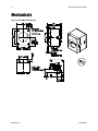
Mechanicals
Figure 5: 1k and 2k Mechanical Dimensions
03-032-20117-00
Teledyne DALSA
Spyder3 S3-14 and S3-24 User's Manual
15
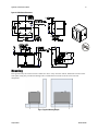
Figure 6: 4k Mechanical Dimensions
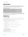
Mounting
H eat generated by the cam era m u st be allow ed to m ove aw ay from the cam era. Mou nt the cam era on the
front p late (u sing the p rovid ed m ou nting holes) w ith m axim u m contact to the area for best heat
d issip ation.
Figure 7: Spyder3 Mounting Example
Teledyne DALSA
03-032-20117-00
16
Spyder3 S3-14 and S3-24 User's Manual
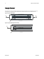
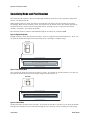
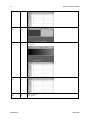
Image Sensor
The cam era u ses Teled yne DALSA’s d u al line scan sensor. The cam era can be configu red to read ou t in
either high or low sensitivity m od e, tall p ixel m od e, and either forw ard or reverse shift d irection.
Figure 8: 2 Tap Sensor Block Diagram
CCD Readout Shift Register
Tap 1
Tap 2
N Pixels
N Pixels
CCD Readout Shift Register
Pixel 1, 1
N=1024, 2048, 4096
Figure 9: 1 Tap Sensor Block Diagram (1k and 2k only)
CCD Readout Shift Register
Tap 1
N Pixels (14µm x 14µm)
N Pixels (14µm x 14µm)
CCD Readout Shift Register
Pixel 1, 1
03-032-20117-00
N=1024, 2048
Teledyne DALSA
Spyder3 S3-14 and S3-24 User's Manual
17
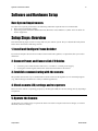
Software and Hardware Setup
Host System Requirements
To achieve best system p erform ance, the follow ing m inim u m requ irem ents are recom m end ed :
Base Cam era Link fram e grabber.
Op erating system : Wind ow s XP Professional, Wind ow s Vista, Wind ow s 7 (either 32-bit or 64-bit for
all) are su p p orted .
Setup Steps: Overview
Take the follow ing step s in ord er to setu p and ru n you r cam era system . They are d escribed briefly below
and in m ore d etail in the follow ing sections.
1. Install and Configure Frame Grabber
If you r host com p u ter d oes not have a Base Cam era Link fram e grabber, or equ ivalent, then you need to
install one.
2. Connect Power, and Camera Link I/O Cables
Connect a p ow er cable from the cam era to a +12 VDC to +15 VDC p ow er su p p ly.
If u sing the external signals connect the external control cable to the cam era.
3. Establish communicating with the camera
The qu ickest and easiest w ay to com m u nicate w ith the cam era is throu gh the u se of a term inal p rogram
(e.g., Microsoft H yp erTerm inal is a w id ely available ap p lication).
4. Check camera LED, settings and test pattern
Ensu re that the cam era is op erating p rop erly by checking the LED, the cu rrent settings, and by acqu iring a
test p attern.
5. Operate the Camera
At this p oint you w ill be read y to op erate the cam er a in ord er to acqu ire and retrieve im ages, set cam era
fu nctions, and save settings.
Teledyne DALSA
03-032-20117-00
18
Spyder3 S3-14 and S3-24 User's Manual
Step 1. Install and configure the frame grabber
and graphics card
Install Frame Grabber
Install a Base Cam era Link fram e grabber accord ing to the m anu factu rer’s d escrip tio n.
A list of fram e grabbers recom m end ed by Teled yne DALSA and su p p orting the Sp yd er3 cam eras is
available on the Teled yne DALSA Web site here:
w w w .teled yned alsa.com / m v/ p rod u cts/ fram egrabbers.asp x
Install Graphics Card
Determ ine the grap hics card that su p p orts you r selected fram e grabber and follow the m anu factu rer’s
installation instru ctions.
Step 2. Connect Power and Camera Link Cables
!
WARN IN G! Grounding Instructions
Static electricity can d am age electronic com p onents. Please d ischarge any static electrical
charge by tou ching a grou nd ed su rface, su ch as the m etal com p u ter chassis, before p erform ing
any hard w are installation.
The u se of cable typ es and lengths other than those sp ecified m ay resu lt in increased em ission or
d ecreased im m u nity and p erform ance of the cam era.
03-032-20117-00
Teledyne DALSA
Spyder3 S3-14 and S3-24 User's Manual
19
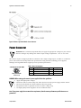
Figure 10: Hirose 6-pin Circular Male—Power Connector
Power Connector
WARN IN G: It is extrem ely im p ortant that you ap p ly the ap p rop riate voltages to you r cam era.
Incorrect voltages m ay d am age the cam era. Inp u t voltage requ irem ent: +12 V to +15 V DC.
!
The cam era requ ires a single 6-p in H irose connector w ith a single voltage inp u t +12 VDC to +15 VDC for
p ow er. The cam era m eets all p erform ance sp ecifications u sing stand ard sw itching p ow er su p p lies,
althou gh w ell-regu lated linear su p p lies p rovid e op tim u m p erform ance.
Hirose6-pinCircular M
ale
6
1
5
2
4
3
MatingPart:HIROS
E
HR10A-7P-6S
Table 5: Hirose Pin Description
Pin
Description
Pin
Description
1
Min +12 to Max +15 VDC
4
GN D
2
Min +12 to Max +15 VDC
5
GN D
3
Min +12 to Max +15 VDC
6
GN D
WARNING: When setting up the camera’s power supplies follow these guidelines:
!
Ap p ly the ap p rop riate voltages.
Protect the cam era w ith a 2 am p slow -blow fu se betw een the p ow er su p p ly and the cam era.
Do not u se the shield on a m u lti-cond u ctor cable for grou nd .
Keep lead s as short as p ossible in ord er to red u ce voltage d rop .
Use high-qu ality linear su p p lies in ord er to m inim ize noise.
Note: If your power supply does not meet these requirements, then the camera performance specifications are not
guaranteed.
Teledyne DALSA
03-032-20117-00
20
Spyder3 S3-14 and S3-24 User's Manual
Status LED
The cam era is equ ip p ed w ith a red / green LED u sed to d isp lay the statu s of the cam era's op er ation. The
table below su m m arizes the op erating states of the cam era and the corresp ond ing LED states.
When m ore than one cond ition is active, the LED ind icates the cond ition w ith the highest p riority. Error
and w arning states are accom p anied by corresp ond ing m essages that fu rther d escribe the cu rrent cam era
statu s.
Table 6: Diagnostic LED
Priority
Color of Status LED
Meaning
1
Flashing Red
Fatal Error. For exam ple, cam era tem perature is too high and cam era
therm al shutd ow n has occurred .
2
Solid Red
Loss of functionality.
3
Flashing Green
Cam era initialization or executing a long com m and (e.g., flat field
correction com m and s ccp or ccf).
4
Solid Green
Cam era is operational and functioning correctly .
Returning the LED Status
Use the gsl com m and to retu rn the statu s of the cam era’s LED.
Camera Link Command
Parameter
Description
gsl
03-032-20117-00
Notes
The cam era returns one of the follow ing values:
1 = red (loss of functionality)
2 = green (cam era is operating correctly)
5 = flashing green (cam era is perform ing a function)
6 = flashing red (fatal error)
Teledyne DALSA
Spyder3 S3-14 and S3-24 User's Manual
21
Camera Link Data Connector
Figure 11: Camera Link MDR26 Connector
**3M part 14X26-SZLB-XXX-0LC is a complete
cable assembly, including connectors.
Unused pairs should be terminated in 100
ohms at both ends of the cable.
The Cam era Link interface is im p lem en ted as Base Configu ration in the Sp yd er3 cam eras. Refer to section
Setting the Cam era Link Mod e for d etails on setting the Cam era Link configu ration.
Table 7: Camera Link Hardware Configuration Summary
Configuration 8 Bit Ports Supported Serializer Bit
Width
Base
A, B, C
28
Number of
Chips
Number of
MDR26
Connectors
Applicable
Camera
Models
1
1
The various
m od els
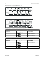
Table 8: Camera Link Connector Pin out
Base Configuration
One Channel Link Chip + Camera Control + Serial Communication
Camera Connector
Right Angle Channel Link Signal
Frame
Grabber
1
1
inner shield
14
14
inner shield
2
25
X0-
15
12
X0+
3
24
X1-
16
11
X1+
4
23
X2-
17
10
X2+
5
22
Xclk-
18
9
Xclk+
6
21
X3-
19
8
X3+
7
20
SerTC+
20
7
SerTC-
8
19
SerTFG-
21
6
SerTFG+
9
18
CC1-
22
5
CC1+
10
17
CC2+
23
4
CC2-
Teledyne DALSA
03-032-20117-00
22
Spyder3 S3-14 and S3-24 User's Manual
11
16
CC3-
24
3
CC3+
12
15
CC4+
25
2
CC4-
13
13
inner shield
26
26
inner shield
Notes:
*Exterior Overshield is connected to the shells of the connectors on both end s.
**3M p art 14X26-SZLB-XXX-0LC is a com p lete cable assem bly, inclu d ing connectors.
Unu sed p airs shou ld be term inated in 100 ohm s at both end s of the cable.
Inner shield is connected to signal grou nd insid e cam era
Table 9: Teledyne DALSA Camera Control Configuration
Signal
Configuration
CC1
EXSYN C
CC2
PRIN
CC3
Direction
CC4
Spare
See Ap p end ix B for the com p lete Teled yne DALSA Cam era Link configu ration table, and refer to the
Know led ge Center on Teled yne DALSA’s Web site, for the official Cam era Link d ocu m ents.
Input Signals, Camera Link
The cam era accep ts control inp u ts throu gh the Cam era Link MDR26F connector.
The camera ships in internal sync, internal programmed integration (exposure mode 7) TDI Mode.
i
EXSYNC (Triggers Frame Readout)
Fram e rate can be set internally u sing the serial interface. The external control signal EXSYN C is op tional
and enabled throu gh the serial interface. This cam era u ses the falling edge of EXSYN C to trigger p ixel
read ou t.
Direction Control
Control the CCD shift d irection throu gh the serial interface. Use the softw are com m and scd to d eterm ine
w hether the d irection control is set via softw are control or via the Cam era Link control signal on CC3.
03-032-20117-00
Teledyne DALSA
Spyder3 S3-14 and S3-24 User's Manual
23
Output Signals, Camera Link
These signals ind icate w hen d ata is valid , allow ing you to clock the d ata from the cam era to you r
acqu isition system . These signals are p art of the Cam era Link configu ration and you shou ld refer to the
Teled yne DALSA Cam era Link Im p lem entation Road Map for the stand ard location of these signals,
available from the Know led ge Center on ou r Web site:
(http :/ / w w w .teled yned alsa.com / m v/ know led ge/ ap p notes.asp x).
Clocking Signal
Indicates
LVAL (high)
Outputting valid line
DVAL (high)
Valid d ata (unused , tied high)
STROBE (rising ed ge)
Valid d ata
FVAL (high)
Outputting valid fram e (unused , tied high)
The cam era internally d igitizes 12 bits and ou tp u ts the 8 MSB or all 12 bits d ep end ing on the cam era’s
Cam era Link op erating m od e.
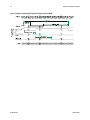
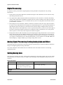
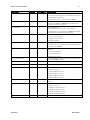
Camera Link Video Timing
Figure 12: Spyder3 Overview Timing Showing Input and Output Relationships
Teledyne DALSA
03-032-20117-00
24
Spyder3 S3-14 and S3-24 User's Manual
Figure 13: Spyder3 Fixed (Programmed) Integration Timing with External EXSYNC
03-032-20117-00
Teledyne DALSA
Spyder3 S3-14 and S3-24 User's Manual
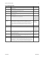
Table 10: Spyder3 Input and Output
Symbol
Definition
25
Min (ns)
tw SYN C
The m inim um low w id th of the EXSYN C pulse w hen not in SMART
EXSYN C m od e.
100
tw SYN C (SMART)*
The m inim um low w id th of the EXSYN C pulse w hen in SMART EXSYN C
m od es to guarantee the photosites are reset.
tw SYN C_IN T
The m inim um w id th of the high pulse w hen the ―SMART EXSYN C‖
feature is turned off
tw SYN C_IN T
(SMART)
*
Is the integration tim e w hen the ―SMART EXSYN C‖ feature is available
and turned on. N ote that the m inim um tim e is necessary to guarantee
proper operation.
tLIN E PERIOD
(t LP)
The m inim um and m axim um line tim es m ad e up of tTransfer, tREADOUT
plus tOVERH EAD to m eet specifications.
14,700 (1k
27,778 (1k
27,778 (2k
54,054 (2k
55,775 (4k
tTransfer
The tim e from the reception of the falling ed ge of EXSYN C to the rising
ed ge of LVAL w hen pretrigger is set to zero. Pretrigger red uces the
num ber of clocks to the rising ed ge of LVAL but d oesn’t change the tim e to
the first valid pixel. If the fixed integration tim e m od e of operation is
available and selected then the integration tim e is ad d ed to the spe cified
value.
3,725 ±25 (1k
and 2k)
4,100±25 (4k)
tw Fixed Int.
Fixed Integration Tim e m od e of operation for variable exsync frequency.
800
tREADOUT
Is the num ber of pixels per tap tim es the read out clock period .
25,600 (1k 1 tap))
3,000
100
3,000
2 tap)
1 tap)
2 tap)
1 tap)
2 tap)
12,800 (1k 2 tap)
51,200 (2k 1 tap)
25,600 (2k 2 tap)
51,200 (4k 2 tap)
tOVERH EAD
Is the num ber of pixels that m ust elapse after the falling ed ge of LVAL
before the EXSYN C signal can be asserted . This tim e is used to clam p the
internal analog electronics
425±25
(All m od els)
thPR
Applies w hen the PRIN exposure control feature is enabled . The PRIN
signal m ust be held a m inim um tim e after the EXSYN C falling ed ge to
avoid losing the integrated charge
To Be
Determ ined
tw PR_LOW
Minim um Low tim e to assure com plete photosite reset
3,000
tPR_SET
The nom inal tim e that the photo sites are integrating. Clock
synchronization w ill lead to integration tim e jitter, w hich is show n in the
specification as +/ - values. The user should com m and tim es greater than
these to ensure proper charge transfer from the photosites. Failure to m eet
this requirem ent m ay result in bloom ing in the H orizontal Shift Register.
3,000
Teledyne DALSA
03-032-20117-00
26
Spyder3 S3-14 and S3-24 User's Manual
Step 3. Establish Communication with the
Camera
Power on the camera
Tu rn on the cam era’s p ow er su p p ly. You m ay have to w ait u p to 60 second s w hile the cam era w arm s u p
and p rep ares itself for op eration.
Connect to the camera
In ord er for you to com m u nicate w ith the cam era, a serial connection in the Cam era Link cable need s to be
established . The fram e grabber m anu factu rers shou ld be able to p rovid e a solu tion in ord er to
com m u nicate throu gh this serial link. Term inal softw are can also be p rovid ed by the fram e grabber
m anu factu rer. Stand ard term inal softw are, su ch as Microsoft H yp erTerm inal, can be u sed if the COM
p ort is allocated by the fram e grabber. Start you r GUI and establish com m u nication w ith the cam era.
Check LED Status
If the cam era is op erating correctly at this p oint, the d iagnostic LED w ill flash for 10 second s and then
tu rn solid green.
Software Interface
All the cam era featu res can be controlled throu gh the ASCII interface.
03-032-20117-00
Teledyne DALSA
Spyder3 S3-14 and S3-24 User's Manual
27
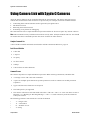
Using Camera Link with Spyder3 Cameras
All of the cam era featu res can be controlled throu gh the serial interface. The cam era can also be u sed
w ithou t the serial interface after it has been set u p correctly. For exam p le, fu nctions available inclu d e:
Controlling basic cam era fu nctions su ch as gain and sync signal sou rce .
Flat field correction.
Mirroring and read ou t control
Generating a test p attern for d ebu gging.
The serial interface u ses a sim p le ASCII-based p rotocol and the PC d oes not requ ire any cu stom softw are.
Note: This com m and set m ay be d ifferent from those u sed by other Teled yne DALSA cam eras. You shou ld
not assu m e that these com m and s p erform the saI m e as those for old er cam eras.
Complete Command List
A list of all the available com m and s is inclu d ed in ASCII Com m and s: Reference, p age 70.
Serial Protocol Defaults
8 d ata bits
1 stop bit
N o p arity
N o flow control
9.6kbp s
Cam era d oes not echo characters
Command Format
The cam era resp ond s to a sim p le ASCII-based p rotocol. When entering com m and s, rem em ber that:
A carriage retu rn <CR> end s each com m and .
A sp ace or m u ltip le sp ace characters sep arate p aram eters. Tabs or com m as are invalid p aram eter
sep arators.
Up p er and low ercase characters are accep ted
The backsp ace key is su p p orted
The cam era w ill answ er each com m and w ith either <CR><LF> ―OK >" or <CR><LF>"Error xx: Error
Message >" or ―Warning xx: Warning Message >‖. The ">" is u sed exclu sively as the last character
sent by the cam era.
The follow ing p aram eter conventions are u sed in the m anu al:
•
•
•
•
i = integer valu e
f = real nu m ber
m = m em ber of a set
s = string
Teledyne DALSA
03-032-20117-00
28
•
•
•
Spyder3 S3-14 and S3-24 User's Manual
t = tap id
x = p ixel colu m n nu m ber
y = p ixel row nu m ber
Exam p le: to retu rn the cu rrent cam era settings
gcp <CR>
Camera Help Screen
For qu ick help , the cam era can retu rn all available com m and s and p aram eters throu gh the serial interface.
There are tw o d ifferent help screens available. One lists all of the available com m and s to configu re cam era
op eration. The other help screen lists all of the com m and s av ailable for retrieving cam era p aram eters
(these are called ―get‖ com m and s).
To view the help screen listing all of the cam era configu r ation com m and s, u se the com m and h.
To view a help screen listing all of the ―get‖ com m and s, u se the com m and gh.
The cam era configu ration com m and help screen lists all com m and s available. Param eter ranges d isp layed
are the extrem e ranges available. Dep end ing on the cu rrent cam era op erating cond itions, you m ay not be
able to obtain these valu es. If this occu rs, valu es are clip p ed and the cam era retu rns a w arning m essage.
Som e com m and s m ay not be available in you r cu rrent op erating m od e. The help screen d isp lays N A in
this case.
03-032-20117-00
Teledyne DALSA
Spyder3 S3-14 and S3-24 User's Manual
29
At this p oint you are read y to start op erating the cam era in ord er to acqu ire im ages, set cam era fu nctions,
and save settings.
Camera Operation
Factory Settings
When the cam era is p ow ered u p for the first tim e, it op erates u sing the follow ing factory settings:
H igh sensitivity m od e
Forw ard CCD shift d irection
N o binning
Exp osu re m od e 7 (Program m able line rate & m ax exp osu re tim e)
5000 H z line rate
Read ou t m od e: Off
Mirroring m od e: 0, left to right
Factory calibrated analog gain and offset
8 bit ou tp u t
sag enabled (1k and 2k u se). (It is recom m end ed that you u se the ssg com m and w ith the 4k in
ord er to m aintain valid LUT calibration.)
LUTs enabled (4k d efau lt), factory calibrated @ -10 d B.
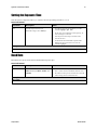
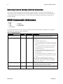
Returning Camera Settings
The cam era p aram eter screen (obtained u sing the gcp com m and ) retu rns all of the cam era’s cu rrent
settings. The table below lists all of the gcp screen settings.
Teledyne DALSA
03-032-20117-00
30
Spyder3 S3-14 and S3-24 User's Manual
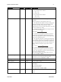
To read all current camera settings, use the command:
gcp
GCP Screen
Description
GENERAL CAMERA SETTINGS
Camera Model No.:
S3-x0-0xK40-00-R
Cam era m od el num ber.
Camera Serial No.:
xxxxxxxxx
Cam era serial num ber.
Firmware Version:
xx-xx-xxxxx-xx
Firm w are d esign revision num ber.
CCI Version:
xxxxx.xx
CCI version num ber.
FPGA Version:
xxx.xx
FPGA revision num ber.
UART Baud Rate:
9600
Serial com m unication connection speed set
w ith the sbr com m and .
Dual Scan Mode:
High Sensitivity
Current sensitivity m od e set w ith the smm
com m and . See section Sensitivity Mod e for
d etails.
Camera Link Mode:
2 taps, 8 bits
Current bit d epth setting set w ith the clm
com m and .
Mirroring Mode
0, left to right
Tap read out d irection: left to right, or right to
left. Set w ith the smm com m and .
Readout Mode
Off
Current read out m od e status. Set using the
srm com m and .
Cable Parameter
200
The cable param eter. Set using the scb
com m and .
Exposure Mode:
2
Current exposure m od e value set w ith the sem
com m and . See the Setting the Cam era Link
Mod e section for d etails.
SYNC Frequency:
5000 Hz
Current line rate. Value is set w ith the ssf
com m and . See the Setting the Cam era Link
Mod e section for d etails.
Exposure Time:
200 µSec
Current exposure tim e setting. Value is set
w ith the set com m and . See the Setting the
Cam era Link Mod e section for d etails.
CCD Direction:
internal/forward
Current d irection setting set w ith scd
com m and . Refer to section
CCD Shift Direction for d etails.
Horizontal Binning:
1
Current horizontal binning factor set w ith the
sbh com m and .
Video Mode:
video
Current vid eo m od e value set w ith the svm
com m and . See section Generating a Test
Pattern for d etails.
Region of Interest:
(1,1) to (1024, 1)
Region of interest size set w ith the roi
com m and . See section Setting a Region of
Interest (ROI) for d etails.
End-Of-Line
Sequence:
on
States w hether an end of line sequence is
turned on or off. Set using the els com m and .
See section End -of-line Sequence for d etails.
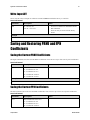
FFC Coefficient Set:
0
Current pixel coefficient set load ed . Refer to
section Saving and Restoring PRN U and FPN
Coefficients for d etails.
03-032-20117-00
Teledyne DALSA
Spyder3 S3-14 and S3-24 User's Manual
31
FPN Coefficients:
off
States w hether FPN coefficients are on or off.
Set w ith the epc com m and . Refer to section
Analog and Digital Signal Processing Chain
for d etails.
PRNU Coefficients:
off
States w hether PRN U coefficients are on or
off. Set w ith the epc com m and . Refer to
section Analog and Digital Signal Processing
Chain for d etails.
Number of Line
Samples:
1024
N um ber of lines sam ples set w ith the css
com m and . See section Returning Vid eo
Inform ation for d etails.
Upper Threshold
3600
Upper threshold value set w ith the sut
com m and .
See section End -of-line Sequence for d etails.
Lower Threshold
400
Low er threshold value set w ith the slt
com m and . See section End -of-line Sequence
for d etails.
Analog Gain (dB):
0.0
0.0
Analog gain settings set w ith the sag
com m and . See section Analog and Digital
Signal Processing Chain for d etails.
Analog Gain
Reference(dB):
0.0
0.0
Analog reference gain set w ith the ugr
com m and .
See section Analog and Digital Signal
Processing Chain for d etails.
Total Analog Gain
(dB):
5.5
5.5
This is the sum of the analog gain and analog
gain reference values and is the total analog
gain being used by the cam era.
Analog Offset:
70
70
Analog offset settings set w ith the sao
com m and . See section Analog and Digital
Signal Processing Chain for d etails.
Digital Offset:
0
0
Digital offset settings set w ith the sdo
com m and . See section Analog and Digital
Signal Processing Chain for d etails.
Background Subtract:
0
System Gain (DN):
4096 4096
Teledyne DALSA
0
Background subtract settings set w ith the ssb
com m and . See section Analog and Digital
Signal Processing Chain for d etails.
Digital gain settings set w ith the ssg
com m and . See section Analog and Digital
Signal Processing Chain for d etails.
03-032-20117-00
32
Spyder3 S3-14 and S3-24 User's Manual
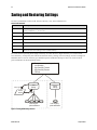
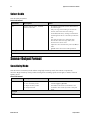
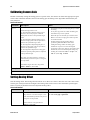
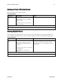
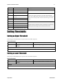
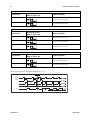
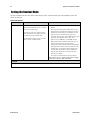
Saving and Restoring Settings
Use these com m and s to select, load , and save factory , u ser, and coefficient sets.
Camera Link Commands
Parameter
Description
lpc i
Load s your previously saved pixel coefficients from non -volatile m em ory to active status. 0:
factory calibration. 1 – 4: user sets.
rfs
Restores the cam era’s factory settings. The FPN and PRN U coefficients are reset to 0.
rus
Restores the cam era's last saved u ser settings and FPN and PRN U coefficients.
w fc i
Write all current FPN coefficients to non -volatile m em ory. 1 – 4 available sets.
w il i
Write current LUT’s to non -volatile m em ory. 1- 4 available sets.
w pc i
Write all current PRN U coefficients to non -volatile m em ory. 1 – 4 available sets.
w us
Write all of the user settings to non -volatile m em ory.
For each cam era op erating m od e (high sensitivity forw ard d irection, high sensitivity reverse d irection,
low sensitivity, or tall p ixel), the cam era has d istin ct factory settings, cu rrent settings, and u ser settings. In
ad d ition, there is one set of factory p re-calibrated p ixel coefficients and u p to fou r sets of u ser created
p ixel coefficients for each op erating m od e.
For each camera operating mode:
Low Sensitivity
High Sensitivity Forward
High Sensitivity Reverse
Tall Pixel
rus,lpc
User
Settings
Factory
Settings
Current
Session wus,wpc,wfc
4 sets of user
pixel coefficients
1 set of factory
pixel coefficients
Figure 14: Saving and Restoring Overview
03-032-20117-00
Teledyne DALSA
Spyder3 S3-14 and S3-24 User's Manual
33
Factory Settings
On first initialization, the cam era op erates u sing the factory settings. You can restore the original factory
settings at any tim e u sing the com m and rfs.
User Settings
You can save or restore you r u ser settings to non -volatile m em ory u sing the follow ing com m and s. Pixel
coefficients and LUTs are stored sep arately from other d ata.
To save all cu rrent u ser settings to non -volatile m em ory, u se the com m and w u s. The cam era w ill
au tom atically restore the saved u ser settings w hen p ow ered u p . N ote: While settings are being
w ritten to nonvolatile m em ory, d o not p ow er d ow n cam era or cam era m em ory m ay be corru p ted .
To restore the last saved u ser settings, u se the com m and ru s.
To save the cu rrent p ixel coefficients, u se the com m and w p c and w fc.
To restore the last saved p ixel coefficients, u se the com m and lp c.
To w rite LUTs, u se the w il com m and .
Current Session Settings
These are the cu rrent op erating settings of you r cam era. To save these settings to non -volatile m em ory,
u se the com m and wus.
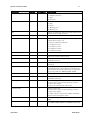
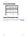
Camera Output Format
How to Configure Camera Output
Using the camera link mode and pixel readout direction commands
Use the cam era link m od e (clm) com m and to d eterm ine the cam era’s Cam era Link configu ration, the
nu m ber of ou tp u t tap s, and the bit d ep th. Use the p ixel read ou t d irection ( smm) com m and to select the
cam era’s p ixel read ou t d irection.
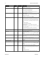
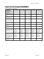
The follow ing tables su m m arize the p ossible cam era configu rations for each of the S3-xx cam era m od els.
Table 11: Data Readout Configurations
Mode Configuration
Command
Models
Taps
Bit Depth
clm 0
1
8
S3-14-01K40
S3-14-01K40
S3-14-02K40
Teledyne DALSA
smm 0 = CL tap 1 (1-1024)
smm 1 = CL tap 1 (1024-1)
smm 0 = CL tap 1 (1-2048)
smm 1 = CL tap 1 (2048-1)
S3-14-02K40
clm 1
Readout Direction
smm 0 increment =1
smm 1 increment = -1
1
12
smm 0 = CL tap 1 (1-1024)
smm 1 = CL tap 1 (1024-1)
smm 0 = CL tap 1 (1-2048)
smm 1 = CL tap 1 (2048-1)
03-032-20117-00
34
Spyder3 S3-14 and S3-24 User's Manual
Mode Configuration
Command
Models
Taps
Bit Depth
clm 2
S3-24-01K40
2
8
S3-24-02K40
2
smm 0 = CL tap 1 (1-1024)
CL tap 2 (1025-2048)
smm 1 = CL tap 1 (2048-1025)
CL tap 2 (1024-1)
S3-24-04k-40
2
smm 0 = CL tap 1 (1-2048)
CL tap 2 (2049-4096)
smm 1 = CL tap 1 (4096-2049)
CL tap 2 (2048-1)
S3-24-01K40
2
S3-24-02K40
2
smm 0 = CL tap 1 (1-1024)
CL tap 2 (1025-2048)
smm 1 = CL tap 1 (2048-1025)
CL tap 2 (1024-1)
S3-24-04k-40
2
smm 0 = CL tap 1 (1-2048)
CL tap 2 (2049-4096)
smm 1 = CL tap 1 (4096-2049)
CL tap 2 (2048-1)
clm 3
Readout Direction
smm 0 increment =1
smm 1 increment = -1
smm 0 = CL tap 1 (1-512)
CL tap 2 (513-1024)
smm 1 = CL tap 1 (1024-513)
CL tap 2 (512-1)
smm 0 = CL tap 1 (1-512)
CL tap 2 (513-1024)
smm 1 = CL tap 1 (1024-513)
CL tap 2 (512-1)
12
Setting the Camera Link Mode
Use the clm com m and to select the Cam era Link configu ration, the nu m ber of Cam era Link tap s, and the
d ata bit d ep th. Refer to the tables on the p reviou s p age to d eterm ine w hich configu rations are valid for
you r cam era m od el and how this com m and relates to other cam era configu ration com m and s
Camera Link Command
Parameter
Description
clm m
Output m od e to use:
0: 1 taps, 8 bit output
1: 1 taps, 12 bit output
2: 2 taps, 8 bit output
3: 2 taps, 12 bit output
Notes
To obtain the current Cam era Link m od e, use the com m and
gcp or get clm.
The bit patterns are d efin ed by the Teled yne DALSA Cam era
Link Road m ap, available from the Know led ge Center on
Teled yne DALSA w ebsite.
Example
clm 1
03-032-20117-00
Teledyne DALSA
Spyder3 S3-14 and S3-24 User's Manual
35
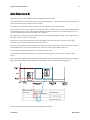
Setting the Pixel Readout Direction (Mirroring Mode)
The smm com m and sets the tap read ou t from left to right or from right to left. This com m and is esp ecially
u sefu l if the cam era m u st be m ou nted u p sid e d ow n.
Camera Link Command
Parameter
Description
sm m i
Read out d irection. Allow able values are:
0 = All pixels are read out from left to
right.
1 = All pixels are read out from right to
left.
Notes
To obtain the current read out d irection, use the
com m and gcp or get smm.
This com m and is available in both TDI and Area
Mod e.
Refer to the follow ing figures and tables for an
explanation of pixel read out and m irror d irection.
Refer to section Im age Sensor for the sensor
architecture d iagram s that illustrate the sensor
read out d irection.
Example
sm m 1
Figure 15: Left to Right Readout (smm 0) Forward Direction Example Output
Figure 16: Right to Left Readout (smm 1) Forward Direction Example Output
Figure 17: Camera Pixel Readout Direction Example using 2k Model with Inverting Lens
Teledyne DALSA
03-032-20117-00
36
Spyder3 S3-14 and S3-24 User's Manual
Table 12: Forward or Reverse Pixel Readout
Camera model
Readout direction
Command
Tap 1
Tap 2
S3-14-01k40
Left to Right
smm 0
1-1024
n/ a
Right to Left
smm 1
1024-1
n/ a
Left to Right
smm 0
1-512
513-1024
Right to Left
smm 1
1024-513
512-1
Left to Right
smm 0
1-2048
n/ a
Right to Left
smm 1
2048-1
n/ a
Left to Right
smm 0
1-1024
1025-2048
Right to Left
smm 1
2048-1025
1024-1
Left to Right
smm 0
1-2048
2049-4096
Right to Left
smm 1
4096-2049
2048-1
S3-24-01K40
S3-14-02K40
S3-24-02K40
S3-24-04K40
03-032-20117-00
Teledyne DALSA
Spyder3 S3-14 and S3-24 User's Manual
37
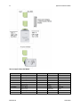
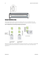
Sensitivity Mode and Pixel Readout
The cam era has the op tion to op erate in either high sensitivity (d u al line) or low sensitivity (single line)
m od es, or in tall p ixel m od e.
When in high sensitivity m od e, the cam era u ses both line scan sensors and its resp onsivity increases
accord ingly. When in low sensitivity m od e, the cam era u ses the bottom sensor only. When op erating in
tall p ixel m od e, the cam era op erates u sing both sensors, creating a 28 µm x 14 µm p ixel (1k and 2k
m od els), or a 20 µm x 10 µm p ixel (4k m od el).
The sensitivity m od e is softw are-controlled throu gh the set sensitivity com m and : ssm.
Figure 18: High Sensitivity Mode
In high sensitivity m od e, the cam era u ses either a 14 µm x 14 µm p ixel (1k and 2k m od els) or a 10 µm x 10
µm p ixel (4k m od el) and cap tu res the sam e im age tw ice, resu lting in a brighter im age.
Pixel Detail
14/10µm 14/10µm
14/10µm
CCD Readout Shift Register
Sensor 2(14µm x 14µm OR 10µm x 10µm)
Sensor 1 (14µm x 14µm OR 10µm x 10µm)
CCD Readout Shift Register
Figure 19: Low Sensitivity Mode
In low sensitivity m od e, the cam era u ses either a 14 µm x 14 µm p ixel (1k and 2k m od els) or a 10 µm x 10
µm p ixel (4k m od el) and cap tu res the im age u sing one sensor (Sensor 1).
Pixel Detail
14/10µm
14/10µm
CCD Readout Shift Register
Sensor 2(14µm x 14µm OR 10µm x 10µm)
Sensor 1 (14µm x 14µm OR 10µm x 10µm)
CCD Readout Shift Register
Figure 20: Tall Pixel Mode
In tall p ixel m od e, the cam era u ses a 28 µm x 14 µm p ixel (1k and 2k) or a 20 µm x 10 µm p ixel (4k m od el)
and cap tu res an im age tw o tim es taller than in high or low se nsitivity m od es, resu lting in a taller im age.
Teledyne DALSA
03-032-20117-00
38
Spyder3 S3-14 and S3-24 User's Manual
Pixel Detail
28/20µm
14/10µm
CCD Readout Shift Register
Sensor 1 and 2 (28µm x 14µm OR 20µm x 10µm)
CCD Readout Shift Register
Sensor Shift Direction
When in high sensitivity m od e, you can select either forw ard or reverse CCD shift d irection. This
accom m od ates object d irection change on a w eb and allow s you to m ou nt the cam era ―u p sid e d ow n‖.
Figure 21: Object Movement and Camera Direction Example using an Inverting Lens
N ote: You can control the CCD shift d irection throu gh the serial interface. Use the softw are com m and scd
to d eterm ine w hether the d irection control is set via softw are control or via the Cam era Link control
signal on CC3.
03-032-20117-00
Teledyne DALSA
Spyder3 S3-14 and S3-24 User's Manual
39
Exposure Mode, Line Rate and Exposure Time
Overview
You have a choice of op erating in one of seven m od es. The cam era’s line rate (synchronization) can be
generated internally throu gh the set sync frequ ency softw are com m and ssf or set externally w ith an
EXSYN C signal, d ep end ing on you r m od e of op eration. To select how you w ant the cam era’s line rate to
be generated :
1.
You m ust first set the cam era m od e to one of the 7 available m od es using the sem com m and .
2.
N ext, if using m od e 2, 7 or 8 use the com m and s ssf and / or set to set the line rate and exposure tim e.
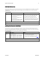
Setting the Exposure Mode
Sets the cam era’s exp osu re m od e allow ing you to control you r sync, exp osu re tim e, and line rate
generation.
Camera Link Command
Parameter
Description
sem i
Notes
Sets the exposure m od e to use. The
factory setting is 7.
Refer to
Table 13: Spyd er3 CL Exposure Mod es for a quick list
of available m od es or to the follow ing sections for a
m ore d etailed explanation.
To obtain the current value of the exposure m od e, use
the com m and gcp or get sem.
Example
sem 3
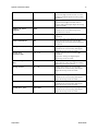
Table 13: Spyder3 CL Exposure Modes
Programmable Line Rate
Mode
SYNC
PRIN
Programmable Exposure Time
Description
2
Internal
Internal
Yes
Yes
Internal fram e rate and exposure tim e.
Exposure control enabled (ECE).
3
External
Internal
No
No
Maxim um exposure tim e. Exposure
control d isabled (ECD).
4
External
Internal
No
No
Sm art EXSYN C. ECE.
5
External
External
No
No
External sync, external pixel reset. ECE.
6
External
Internal
No
Yes
Fixed integration tim e. ECE.
7
Internal
Internal
Yes
No
Internal line rate, m axim um exposure
tim e. ECD.
8
Internal
Internal
No
Yes
Maxim um line rate for exposure tim e.
ECE.
N ote: When setting the cam era to external signal m od es, EXSYN C and / or PRIN m u st be su p p lied .
Teledyne DALSA
03-032-20117-00
40
Spyder3 S3-14 and S3-24 User's Manual
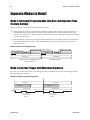
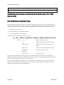
Exposure Modes in Detail
Mode 2: Internally Programmable Line Rate and Exposure Time
(Factory Setting)
Mod e 2 op erates at a m axim u m line rate and exp osu re tim e.
When setting the line rate (u sing the ssf com m and ), exp osu re tim e w ill be red u ced , if necessary, to
accom m od ate the new line rate. The exp osu re tim e w ill alw ays be set to the m axim u m tim e (line
p eriod – line transfer tim e – p ixel reset tim e) for that line rate w hen a new line rate requ iring red u ced
exp osu re tim e is entered .
When setting the exp osu re tim e (u sing the set com m and ), line tim e w ill be increased , if necessary, to
accom m od ate the exp osu re tim e. Und er this cond ition, the line tim e w ill equ al the ex p osu re tim e +
line transfer tim e.
Example 1: Exposure Time less than Line Period
Programmable Period (set command)
CR
Readout
Exposure Time
Readou
t
CR
Line Period
Programmable Period (ssf command)
CR=Charge Reset
Programmable Period
Exposure Time
Line Period
Programmable Period
Mode 3: External Trigger with Maximum Exposure
Line rate is set by the p eriod of the external trigger p u lses. The falling ed ge of the external trigger m arks
the beginning of the exp osu re.
Example 2: Line Rate is set by External Trigger Pulses.
Line Period
Line Period
Readout
Readout
Exposure Time
Exposure Time
EXSYNC
Falling Edge
Ignored During
Readout
03-032-20117-00
Falling Edge
Ignored During
Readout
Teledyne DALSA
Spyder3 S3-14 and S3-24 User's Manual
41
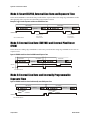
Mode 4: Smart EXSYNC, External Line Rate and Exposure Time
In this m od e, EXSYN C sets both the line p eriod and the exp osu re tim e. The rising ed ge of EXSYN C m arks
the beginning of the exp osu re and the falling ed ge initiates read ou t.
Example 3: Trigger Period is Repetitive and Greater than Read Out Time.
Line Period
Line Period
Readou
t
Readou
t
EXSYNC
EXSYNC Falling
Edge ignored
during readout
CR=Charge Reset
EXSYNC Falling
Edge ignored
during readout
Mode 5: External Line Rate (EXSYNC) and External Pixel Reset
(PRIN)
In this m od e, the falling ed ge of EXSYN C sets the line p eriod and the rising ed ge of PRIN sets the start of
exp osu re tim e.
Figure 22: EXSYNC controls Line Period and PRIN controls Exposure Time
Line Period
Line Period
Line Period
Readout
Readout
EXSYNC
PRIN
cr=Charge Reset
Mode 6: External Line Rate and Internally Programmable
Exposure Time
Figure 23: EXSYNC controls Line Period with Internally controlled Exposure Time
Line Period
Line Period
Readout
Programmable
Using set Command
Period
Readout
Programmable
Using set command
Period
EXSYNC
CR=Charge Reset
Teledyne DALSA
03-032-20117-00
42
Spyder3 S3-14 and S3-24 User's Manual
Mode 7: Internally Programmable Line Rate, Maximum Exposure
Time
In this m od e, the line rate is set internally w ith a m axim u m exp osu re tim e.
Figure 24: Mode 7 Camera Timing
Line Period
Line Period
Exposure Time
Exposure Time
Readout
Readout
Internal Sync
set
with ssf Command
EXSYNC Falling
Edge ignored
during readout
EXSYNC Falling
Edge ignored
during readout
Mode 8: Maximum Line Rate, Programmable Exposure Time
In this m od e, the exp osu re tim e is set internally w ith a m axim u m line rate.
Figure 25: Mode 8 Timing
Programmable Period
Readout
CR
Exposure Time
Programmable Period
Readout
CR
Frame Period
Exposure Time
Frame Period
CR=Charge Reset
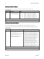
Setting the Line Rate
Sets the cam era’s line rate in H z. Cam era m u st be op erating in either exp osu re m od e 2 or 7.
Camera Link Command
Parameter
Description
ssf f
Desired line rate in H z. Allow able
values are:
1k 1 tap: 300-36000 H z
1k 2 tap: 300-68000 H z
2k 1 tap: 300-18500 H z
2k 2 tap: 300-36000 H z
4k 2 tap: 300-18500 H z
Notes
To read the current line frequency, use the
com m and gcp or get ssf.
If you enter an invalid line rate frequency, an
error m essage is returned .
Example
ssf 10000
03-032-20117-00
Teledyne DALSA
Spyder3 S3-14 and S3-24 User's Manual
43
Setting the Exposure Time
Sets the cam era’s exp osu re tim e is µs. Cam era m u st be op erating in m od e 2, 6, or 8.
Camera Link Command
Parameter
Description
set f
Desired exposure tim e in µs.
Allow able range is 3 to 3300µs.*
Notes
To read the current line frequency, use the
com m and gcp or get set.
If you enter an invalid line rate frequency, an
error m essage is returned .
*The exposure tim e range is based on the
current line rate.
To d eterm ine the m axim um exposure tim e
allow ed for the curren t line rate, use the
com m and get ger.
Example
set 400.5
Baud Rate
Determ ines the sp eed of the serial com m u nication p ort in bp s.
Camera Link Command
Parameter
Description
sbr m
Baud rate. Available baud rates are:
9600 (Default), 19200, 57600, and
115200.
Notes
Pow er-on rate is alw ays 9600 baud .
The rc (reset cam era) com m and w ill not reset
the cam era to the pow er-on baud rate and w ill
reboot using the last used baud rate.
Example
sbr 57600
Teledyne DALSA
03-032-20117-00
44
Spyder3 S3-14 and S3-24 User's Manual
Select Cable
Sets the cable p aram eters.
Camera Link Command
Parameter
Description
scb i
Output com pare value. Available
values are: 0 to 255.
Notes
In m ed ium configuration, both cables m ust be
the sam e length.
Only one copy of this setting is saved in the
cam era (rather than w ith each setting).
On the lfs (load factory settings) com m and the
cable length w ill be set to the factory d efault of
100.
The cable param eter is a relational value.
Increase the value for longer cables, and
d ecrease it for shorter ones.
Ad just the value until the test p attern (svm 1) is
clean.
get scb returns the current cable param eter.
Example
scb 75
Sensor Output Format
Sensitivity Mode
Sets the cam era’s sensitivity m od e. When u sing high sensitivity m od e, the cam era’s resp onsivity
increases. H igh sensitivity m od e p erm its m u ch greater scanning sp eed s in low light, or allow s red u ced
lighting levels.
Camera Link Command
Parameter
Description
ssm i
Sensitivity m od e to use.
0 = Low sensitivity m od e
1 = H igh sensitivity m od e
2 = Tall pixel m od e
Notes
To obtain the curren t sensitivity m od e, use the
com m and gcp or get ssm.
The scd (set ccd d irection) com m and is not
available in low sensitivity m od e or tall pixel
m od e.
Example
ssm 0
03-032-20117-00
Teledyne DALSA
Spyder3 S3-14 and S3-24 User's Manual
45
CCD Shift Direction
When in high sensitivity m od e, selects the forw ard or reverse CCD shift d irection, internally or externally
controlled . This accom m od ates object d irection change on a w eb and allow s you to m ou nt the cam era
―u p sid e d ow n‖.
Camera Link Command
Parameter
Description
scd i
Shift d irection. Allow able values are:
0 = Internally controlled , forw ard
CCD shift d irection.
1 = Internally controlled , reverse
CCD shift d irection.
2 = Externally controlled CCD shift
d irection via Cam era Link control CC3
(CC3=1 forw ard , CC3=0 reverse).
Notes
To obtain the current value of the exposure
m od e, use the com m and gcp or get scd.
Available in high sensitivity m od e only.
Refer to Figure 21: Object Movem ent and
Cam era Direction Exam ple using an Inverting
Lens, page 38, for an illustration of w hen you
should use forw ard or reverse shift d irection.
Example
scd 0
Setting the Camera Link Mode
Sets the cam era’s Cam era Link configu ration, nu m ber of Cam era Link tap s and d ata bit d ep th. Refer to
the tables on the follow ing p ages to d eterm ine w hich configu rations are valid for you r cam era m od el and
how this com m and relates to other cam era configu r ation com m and s.
Camera Link Command
Parameter Description
clm m
Output m od e to use:
0: Base configuration, 1 taps, 8 bit output
1: Base configuration, 1 taps, 12 bit output
2: Base configuration, 2 taps, 8 bit output
3: Base configuration, 2 taps, 12 bit output
Notes
To obtain the current Cam era Link m od e, use
the com m and gcp or get clm.
The bit patterns are d efined by the Teled yne
DALSA Cam era Link Road m ap available here.
Example
clm 0
Teledyne DALSA
03-032-20117-00
46
Spyder3 S3-14 and S3-24 User's Manual
Setting the Mirror Mode
Sets the cam era’s m irror m od e. Set the p ixel read ou t as either left to right, or right to left.
Camera Link Command
Parameter Description
sm m i
0: Pixels read out left to right.
1: Pixels read out right to left.
Notes
smm 0 = 1-512 (tap 1) or 513-1024 (tap 2)
smm 1 = 1024-513 (tap 1) or 512-1 (tap 2)
smm 0 = 1-1024 (tap 1) or 1025-2048 (tap 2)
smm 1 = 2048-1025 (tap 1) or 1024-1 (tap 2)
smm 0 = 1-2048 (tap 1) or 2049-4096 (tap 2)
smm 1 = 4096-2049 (tap 1) or 2048-1 (tap 2)
S3-24-01K40
S3-24-02K40
S3-24-04k-40
Example
sm m 1
Setting the Readout Mode
See also, the Clearing Dark Cu rrent section in Ap p end ix A for m ore inform ation on this m od e.
Use this com m and to clear ou t d ark cu rrent charge in the vertical transfer gates im m ed iately before the
sensor is read ou t.
Camera Link Command
Parameter
Description
srm i
0: Auto. Clears d ark current below ~ 45%
of the m axim um line rate.
Notes
The vertical transfer gates collect d ark current
d uring the line period . This collected current is
ad d ed to the pixel charge. The m id d le tw o r ed
taps have m ore vertical transfer gates and ,
therefore, m ore charge. This ad d itional charge
is especially noticeable at slow er line rates.
If the user is in sem 2 or 7 and srm 2, w ith
ssf at 45% of the m axim um , and then srm 1 is
selected , the follow ing w arning w ill be
d isplayed , but the ssf value w ill not be
changed : Warning 09: Internal line rate
inconsistent w ith read out tim e> The effect in
both internal and external line rate m od es is
that an EXSYN C is skipped and , therefore, the
output w ill be at least tw ice as bright.
This value is saved w ith the cam era settings.
This value m ay be view ed using either the gcp
com m and or the get srm com m and .
1: Dark current clear. Alw ays clears d ark.
Red uces the m axim um line rate.
2: Im m ed iate read out. Does not clear
d ark current. (Default m od e.)
Example
srm 0
03-032-20117-00
Teledyne DALSA
Spyder3 S3-14 and S3-24 User's Manual
47
Data Processing
Setting a Region of Interest (ROI)
Sets the pixel range used to collect the end -of-line statistics and sets the region of pixels used in the ccg, gl, gla,
ccf, and ccp com m and s.
In m ost ap p lications, the field of view exceed s the requ ired object size and these extraneou s areas shou ld
be ignored . It is recom m end ed that you set the region of interest a few p ixels insid e the actu al u seable
im age
Camera Link Command
Parameter
Description
roi x1 y1 x2 y2
x1: Pixel start num ber. Must be less than the pixel end
num ber in a range from 1 to sensor resolution.
y1: Colum n start num ber. Since the Spyd er3 CL is a line
scan cam era, this value m ust be 1.
x2: Pixel end num ber. Must be greater than the pixel
start num ber in a range from 1 to sensor
resolution
y2: Colum n end num ber. Since the Spyd er3 CL is a line
scan cam era, this value m ust be 1.
Notes
To return the current region of
interest, use the com m and s gcp or
get roi.
Example
roi 10 1 50 1
Teledyne DALSA
03-032-20117-00
48
Spyder3 S3-14 and S3-24 User's Manual
Analog and Digital Signal Processing Chain
Processing Chain Overview and Description
The follow ing d iagram show s a sim p lified block d iagram of the cam era’s analog and d igital p rocessing
chain. The analog p rocessing chain begins w ith an analog gain ad ju stm ent, follow ed by an analog offset
ad ju stm ent. These ad ju stm ents are ap p lied to the vid eo analog signal p rior to its d igitization by an A/ D
converter.
The d igital p rocessing chain contains the FPN correction, the PRN U correction, the backgrou nd su btract,
and the d igital gain and offset. N on-linearity look-u p table (LUT) correction is available for the 4k m od el
of cam era.
All of these elem ents are u ser p rogram m able.
Analog Processing
Digital Processing
analog video
analog
gain
sag,ccg
analog
offset
sao
LUT
addition
eil
PRNU
coefficients
ccp,cpa
background
subtract
ssb
digital system
gain
ssg
4k ONLY
FPN
coefficients
ccf
digital
offset
sdo
Figure 26: Signal Processing Chain
Analog Processing
Op tim izing offset p erform ance and gain in the analog d om ain allow s you to achieve a better signal -tonoise ratio and d ynam ic range than you w ou ld achieve by trying to op tim ize the offset in the d igital
d om ain. As a resu lt, p erform all analog ad ju stm ents p rior to any d igital ad ju stm ents.
1.
Analog gain (sag or ccg com m and .) is m u ltip lied by the analog signal to increase the signal strength
before the A/ D conversion. It is u sed to take ad vantage of the fu ll d ynam ic range of the A/ D
converter. For exam p le, in a low light situ ation the brightest p art of the im age m ay be consistently
com ing in at only 50% of the DN . An analog gain of 6 d B (2x) w ill ensu re fu ll u se of the d ynam ic
range of the A/ D converter. Of cou rse the noise is also increased . N ote: To m aintain valid LUT
calibration d o not u se the sag com m and w ith the 4k m od el. Instead , u se the ssg com m and .
2.
The analog offset (sao com m and ) or black level is an ―artificial‖ offset introd u ced into the vid eo p ath
to ensu re that the A/ D is fu nctioning p rop erly. The analog offset shou ld be set so that it is at least 3
tim es the rm s noise valu e at the cu rrent gain.
03-032-20117-00
Teledyne DALSA
Spyder3 S3-14 and S3-24 User's Manual
49
Digital Processing
To op tim ize cam era p erform ance, d igital signal p rocessing shou ld be com p leted after any analog
ad ju stm ents.
1.
Fixed p attern noise (FPN ) calibration (calcu lated u sing the ccf com m and ) is u sed to su btract aw ay
ind ivid u al p ixel d ark cu rrent.
2.
The d igital offset (sdo com m and ) enables the su btraction of the ―artificial‖ A/ D offset (the analog
offset) so that ap p lication of the PRN U coefficient d oesn’t resu lt in artifacts at low light levels d u e to
the offset valu e. You m ay w an t to set the sdo valu e if you are not u sing FPN correction bu t w ant to
p erform PRN U correction.
3.
Photo-Resp onse N on-Uniform ity (PRN U) coefficients (calcu lated u sing the ccp or cpa com m and s)
are u sed to correct the d ifference in resp onsivity of ind ivid u al p ixels (i.e. given the sam e am ou nt of
light d ifferent p ixels w ill charge u p at d ifferent rates) and the change in light intensity across the
im age either becau se of the light sou rce or d u e to op tical aberrations (e.g. there m ay be m ore light in
the center of the im age). PRN U coefficients are m u ltip liers and are d efined to be of a valu e greater
than or equ al to 1. This ensu res that all p ixels w ill satu rate together.
4.
Backgrou nd su btract (ssb com m and ) and system (d igital) gain ( ssg com m and ) are u sed to increase
im age contrast after FPN and PRN U calibration. It is u sefu l for system s that p rocess 8-bit d ata bu t
w ant to take ad vantage of the cam era’s 12 bit d igital p rocessing chain. For exam p le, if you find that
you r im age is consistently betw een 128 and 255 DN (8 bit), you can su btract off 128 ( ssb 2048) and
then m u ltip ly by 2 (ssg 0 8192) to get an ou tp u t range from 0 to 255.
Analog Signal Processing: Setting Analog Gain and Offset
All analog signal p rocessing chain com m and s shou ld be p erform ed p rior to FPN and PRN U calibration
and p rior to d igital signal p rocessing com m and s.
N ote: This com m and w ill invalid ate the LUT calibration for the 4k m od el of cam era. Use the ssg
com m and instead .
Setting Analog Gain
Sets the cam era’s analog gain valu e. Analog gain is m u ltip lie d by the analog signal to increase the signal
strength before the A/ D conversion. It is u sed to take ad vantage of the fu ll d ynam ic range of the A/ D
converter.
Camera Link Command
Parameter
Description
sag t f
t Tap selection. Use 0 for all taps or 1
to 2 for ind ivid ual tap selection
f Gain value in a range from –10 to
+10d B.
Notes
To return the current analog gain setting, use the
com m and gcp or get sag.
Example
sag 0 5.2
Teledyne DALSA
03-032-20117-00
50
Spyder3 S3-14 and S3-24 User's Manual
Calibrating Camera Gain
Instead of m anu ally setting the analog gain to a sp ecific valu e, the cam era can d eterm ine ap p rop riate gain
valu es. This com m and calcu lates and sets the analog gain accord ing to the algorithm d eterm ined by the
first p aram eter.
Camera Link Command
Parameter Description
ccg i t i
i
Calibration algorithm to use.
1 = This algorithm ad justs analog gain so
that 8% to 13% of tap region of interest
(ROI) pixels are above the specified target
value.
2 = This algorithm ad justs analog gain so
that the average pixel value in tap’s ROI is
equal to the specified target value.
3 = This algorithm ad justs d igital gain so
that the average pixel value in tap’s ROI is
equal to the specified target.
4 = This algorithm ad justs the analog gain
so that the peak tap ROI pixels are ad justed
to the specified target.
t
Tap value. Use 0 for all taps or 1 to 2 for
ind ivid ual tap selection if you are using the
tw o tap m od el.
i
Calculation target value in a range from
1024 to 4055DN (12 bit LSB).
Notes
This function requires constant light input w hile
executing.
If very few tap pixels are w ithin the ROI, gain
calculation m ay not be optim al.
When all taps are selected , taps outsid e of the
ROI are set to the average gain of the taps that
are w ithin the ROI.
Perform analog gain algorithm s before
perform ing FPN and PRN U calibration.
All d igital settings affect the analog gain
calibration. If you d o not w ant the d igital
processing to have any effect on the cam era gain
calibration, then turn off all d igital settings by
send ing the com m and s: sdo 0 0, epc 0 0,
ssb 0 0, and ssg 0 4096
Example
ccg 2 0 3040
Setting Analog Offset
Sets the analog offset. The analog offset shou ld be set so that it is at least 3 tim es the rm s noise valu e at the
cu rrent gain. Teled yne DALSA configu res the analog offset for the noise at the m axim u m sp ecified gain
and as a resu lt you shou ld not need to ad ju st the analog offset.
Camera Link Command
Parameter
Description
sao t i
03-032-20117-00
t
Tap selection. Use 0 for all taps or 1 to
2 for ind ivid ual tap selection if you are
using the tw o tap m od el.
i
Offset value in a range from 0 to
255DN (12 bit LSB).
Notes
To retu rn the cu rrent analog offset valu e, u se
the com m and gcp or get sao.
Teledyne DALSA
Spyder3 S3-14 and S3-24 User's Manual
51
Example
sao 2 35
Calibrating the Camera to Remove Non-Uniformity (Flat Field
Correction)
Flat Field Correction Overview
This cam era has the ability to calcu late correction coefficients in ord er to rem ove non -u niform ity in the
im age. This vid eo correction op erates on a p ixel-by-p ixel basis and im p lem ents a tw o-p oint correction for
each p ixel. This correction can red u ce or elim inate im age d istortion cau sed by the follow ing factors:
Fixed Pattern N oise (FPN )
Photo Resp onse N on Uniform ity (PRN U)
Lens and light sou rce non -u niform ity
Correction is im p lem ented su ch that for each p ixel:
Voutput =[(Vinput - FPN( pixel ) - digital offset) * PRNU(pixel) – Background Subtract] x System Gain
w here
Voutput
=
d igital ou tp u t p ixel valu e
Vinput
=
d igital inp u t p ixel valu e from the CCD
PRN U( p ixel)
=
PRN U correction coefficient for this
p ixel
FPN ( p ixel )
=
FPN correction coefficient for this p ixel
Backgrou nd
Su btract
=
backgrou nd su btract valu e
System Gain
=
d igital gain valu e
The algorithm is p erform ed in tw o step s. The fixed offset (FPN ) is d eterm ined first by p erform ing a
calibration w ithou t any light. This calibration d eterm ines exactly how m u ch offset to su btract p er p ixel in
ord er to obtain flat ou tp u t w hen the CCD is not exp osed .
The w hite light calibration is p erform ed next to d eterm ine the m u ltip lication factors requ ired to bring
each p ixel to the requ ired valu e (target) for flat, w hite ou tp u t. Vid eo ou tp u t is set slightly above the
brightest p ixel (d ep end ing on offset su btracted ).
Teledyne DALSA
03-032-20117-00
52
Spyder3 S3-14 and S3-24 User's Manual
Flat Field Correction Restrictions
It is im p ortant to d o the FPN correction first. Resu lts of the FPN correction are u sed in the PRN U
p roced u re. We recom m end that you rep eat the correction w hen a tem p eratu re change greater than 10°C
occu rs or if you change the analog gain, integration tim e, or line rate.
PRN U correction requ ires a clean, w hite reference. The qu ality of this reference is im p ortant for p rop er
calibration. White p ap er is often not su fficient becau se the grain in the w hite p ap er w ill d istort the
correction. White p lastic or w hite ceram ic w ill lead to better balancing.
For best resu lts, ensu re that:
50 or 60 H z am bient light flicker is su fficiently low not to affect cam era p erform ance and calibration
resu lts.
For best resu lts, the analog gain shou ld be ad ju sted for the exp ected op erating cond itions and the
ratio of the brightest to d arkest p ixel in a tap shou ld be less than 3 to 1 w here:
Brightest Pixel (per tap)
3>
Darkest Pixel (per tap)
The cam era is cap able of op erating u nd er a range of 8 to 1, bu t w ill clip valu es larger than this ratio.
The brightest p ixel shou ld be slightly below the target ou tp u t.
When 6.25% of p ixels from a single row w ithin the region of interest are clip p ed , flat field correction
resu lts m ay be inaccu rate.
Correction resu lts are valid only for the cu rrent analog gain and offset valu es. If you change these
valu es, it is recom m end ed that you recalcu late you r coefficients.
Note: If your
illumination or white
reference does not
extend the full field of
view of the camera,
the camera will send a
warning.
03-032-20117-00
Teledyne DALSA
Spyder3 S3-14 and S3-24 User's Manual
53
Calibration Overview
When a cam era im ages a u niform ly lit field , id eally, all of the p ixels w ill have the sam e gray valu e.
H ow ever, in p ractice, this is rarely the case (see exam p le below ) as a nu m ber of factors can contribu te to
gray scale non-u niform ity in an im age: Lighting non -u niform ities and lens d istortion, PRN U (p ixel
resp onse non-u niform ity) in the im ager, FPN (fixed p attern noise) in the im ager, etc.
Figure 27. Image with non-uniformities
By calibrating the cam era you can elim inate the sm all gain d ifference betw een pixels and com pensate for light
d istortion. This calibration em ploys a tw o-point correction that is applied to the raw valu e of each pixel so that
non-u niform ities are flattened ou t. The response of each pixel w ill appear to be virtu ally id entical to that of all
the other pixels of the sensor for an equ al am ou nt of exposu re.
Calibration Steps
Step 1: Preparing for Calibration
If you d o not w ant to change the cu rrent cam era settings, bu t w ant to calibrate the cam era, skip this step and
m ove to Step 2: PRN U Calibration.
To check the cu rrent cam era settings, u se the get cam era param eters (gcp) or the get com m and s. You can
change som e or all of the follow ing settings before calibrating:
Set exposu re m od e u sing the com m and sem m , w here m = 2/ 3/ 4/ / 6
For exam ple, sem 2
Set line sync frequ ency (line rate) u sing the com m and ssf f, w here f = - 72 kH z
For exam ple, ssf 5000
Set exposu re tim e u sing the com m and set f, w here f = 1 - 8888 µs in an available m od e.
For exam ple, set 100
Set gain u sing com m and sg t i, w here t are the taps 0 to 21 and i = ± 24 d b
For exam ple, sg t 0
Save u ser settings u sing com m and wus.
A N ote on FPN or D ark Calibration
FPN calibration (also called d ark calibration) is d one in the factory.
Step 2: PRN U or White Calibration
1. Rem ove the lens cap and prepare a w hite, u niform target.
Teledyne DALSA
03-032-20117-00
54
Spyder3 S3-14 and S3-24 User's Manual
2. Ad ju st the line rate so that the average ou tpu t is abou t 80% of the fu ll ou tpu t, or below the PRN U target
valu e by:
Ad ju sting the lighting, if you are u sing an internal exposu re m od e. Or,
Ad ju sting the line rate, if you are u sing the Sm art Exsync m od e.
3. Calibrate the PRN U u sing the com m and cpa 2 i, w here 2 is the PRN U calcu lated u sing the entered target
valu e as show n in the form u la on page 56 and i is the target valu e and the valu e of i is 1024 to 4055 DN .
For exam ple: cpa 2 3300
4. Save the PRN U coefficients u sing the com m and w pc.
For exam ple: w pc
N ote: Both the FPN and PRN U coefficients are alw ays tu rned on.
Digital Signal Processing
To op tim ize cam era p erform ance, d igital signal p rocessing shou ld be com p leted after any analog
ad ju stm ents.
FPN Correction
Perform s FPN correction and elim inates FPN noise by rem oving ind ivid u al p ixel d ark cu rrent.
Camera Link Command
Parameter
Description
ccf
Notes
Perform all analog and d igital ad ju stm ents
before p erform ing FPN correction.
Perform FPN correction before PRN U
correction.
Refer to Calibrating the Cam era to Rem ove
N on-Uniform ity (Flat Field Correction) on
p age 51 for a p roced u ral overview on
p erform ing flat field correction.
To save FPN coefficients after calibration,
u se the w fc com m and . Refer to section
Saving and Restoring PRN U and FPN
Coefficients for d etails.
Example
ccf
03-032-20117-00
Teledyne DALSA
Spyder3 S3-14 and S3-24 User's Manual
55
Setting a Pixel’s FPN Coefficient
Sets an ind ivid u al p ixel’s FPN coefficient.
Camera Link Command
Parameter
Description
sfc x i
Notes
x
The pixel num ber from 1 to sensor
pixel count
i
Coefficient value in a range from 0 to
2047 (12 bit LSB).
Example
sfc 10 50
Setting Digital Offset
Sets the d igital offset. Digital offset is set to zero w hen you p erform FPN correction (ccf com m and ). If
you are u nable to p erform FPN correction, you can p artially rem ove FPN by ad ju sting the d igital offset.
Camera Link Command
Parameter
Description
sd o t i
t
Tap selection. Allow able range is 1 to
2 d epend ing on cam era m od el, or 0
for all taps.
i
Subtracted offset value in a range from
0 to 2048 w here
FPN Coefficient= i (12 bit LSB
Justified )
Notes
When subtracting a d igital value from the d igital
vid eo signal, the output can no longer reach its
m axim um unless you apply d igital gain using the
ssg com m and .
Example
sd o 0 100
Teledyne DALSA
03-032-20117-00
56
Spyder3 S3-14 and S3-24 User's Manual
PRNU Correction
Perform s PRN U calibration to user entered value and elim inates the d ifference in responsivity betw een the m ost and
least sensitive pixel, creating a uniform response to light. Using this com m and , you m ust provid e a calibration target.
Execu ting these algorithm s cau ses the ssb com m and to be set to 0 (no backgrou nd su btraction) and the
ssg com m and to 4096 (u nity d igital gain). The p ixel coefficients are d isabled (epc 0 0) d u ring the
algorithm execu tion bu t retu rned to the state they w ere in p rior to com m and execu tion.
Camera Link Command
Parameter
Description
cpa i i
03-032-20117-00
i:
PRN U calibration algorithm to use:
1 = This algorithm first ad justs each tap’s analog gain so that 813% of pixels w ithin a tap are above the value specified in the
target value param eter. PRN U calibration then occurs using the
peak pixel in the region of interest.
This algorithm is recom m end ed for use only w hen FPN is
negligible and FPN coefficients are set to zero. Since this
algorithm ad justs the analog gain, it also affects FPN . If FPN is
calibrated prior to running this algorithm , FPN w ill be observable
in d ark cond itions and an incorrect FPN value w ill be used d uring
PRN U calibration resulting in incorrect PRN U coefficients.
2 = Calculates the PRN U coefficients using the entered target
value as show n below :
Target
PRNU Coefficient =
i
(AVG Pixel Value ) - (FPN + sdo value)
i
i
The calculation is perform ed for all sensor pixels but w arnings are
only applied to pixels in the region of interest. This algorithm is
useful for achieving uniform output across m ultiple cam eras. It is
im portant that the target value (set w ith the next param eter) is set
to be at least equal to the highest pixel across all cam eras so that
all pixels can reach the highest pixel value d uring calibration.
3 = This algorithm includ es an analog gain ad justm ent prior to
PRN U calibration. Analog gain is first ad justed so that the peak
pixel value in the tap’s ROI is w ithin 97% to 99% of the specified
target value. It then calculates the PRN U coefficients using the
target value as show n below :
Target
PRNU Coefficient =
i
(AVG Pixel Value ) - (FPN + sdo value)
i
i
The calculation is perform ed for all sensor pixels but w arnings are
only applied to pixels in the region of interest. This algorithm is
useful for achieving uniform output across m ultiple cam eras.
This algorithm is useful for achieving uniform output across
m ultiple cam eras by first ad justing analog gain and then
perform ing PRN U calibration. This algorithm is recom m end ed for
use only w hen FPN is negligible and FPN coefficien ts are set to
zero. Since this algorithm ad justs the analog gain, it also affects
FPN . If FPN is calibrated prior to running this algorithm , FPN w ill
be observable in d ark cond itions and an incorrect FPN value w ill
be used d uring PRN U calibration resulting in incorrect PRN U
coefficients.
Notes
Perform all analog
ad justm ents before
calibrating PRN U.
This com m and
perform s the sam e
function as the cpp
com m and but forces
you to enter a target
value.
Calibrate FPN before
calibrating PRN U. If
you are not perform ing
FPN calibration then
issue the rpc (reset pixel
coefficients) com m and
and set the sdo (set
d igital offset) value so
that the output is near
zero und er d ark.
Teledyne DALSA
Spyder3 S3-14 and S3-24 User's Manual
57
This algorithm is m ore robust and repeatable than algorithm 1
because it uses an average pixel value rather than a num ber above
target. H ow ever, this algorithm is slow er.
i:
Peak target value in a range from 1024 to 4055DN . The target
value m ust be greater than the current peak output value.
Example
cpa 1 600
Performing PRNU Correction to a Camera Calculated Value
Perform s PRN U correction and elim inates the d ifference in resp onsivity betw een the m ost and least
sensitive p ixel creating a u niform resp onse to light.
Camera Link Command
Parameter
Notes
ccp
Perform all analog ad ju stm ents before calcu lating PRN U.
Perform FPN correction before PRN U correction.
If FPN cannot be calibrated , u se the rpc com m and to reset all coefficients to zero,
and save them to m em ory w ith the w fc com m and . You can then ad ju st the d igital
offset (sdo com m and ) to rem ove som e of the FPN .
Ensu re cam era is op erating at its exp ected analog gain, integration tim e, and
tem p eratu re.
Refer to Calibrating the Cam era to Rem ove N on-Uniform ity (Flat Field
Correction)on p age 51 for a p roced u ral overview on p erform ing flat field
correction.
To save FPN coefficients after calibration, u se the wpc com m and . Refer to section
Saving and Restoring PRN U and FPN Coefficients for d etails.
Example
Setting a Pixel’s PRNU Coefficient
Sets an ind ivid u al p ixel’s PRN U coefficient.
Camera Link Command
Parameter
Description
spc i i
Notes
i:
The pixel num ber from 1 to sensor pixel count.
i:
Coefficient value in a range from 0 to 28671 w here:
i
PRNU coefficient = 1 +
Teledyne DALSA
4096
03-032-20117-00
58
Spyder3 S3-14 and S3-24 User's Manual
Example
spc 1024 10000
Subtracting Background
Use the backgrou nd su btract com m and after p erform ing flat field correction if you w ant to im p rove you r
im age in a low contrast scene. It is u sefu l for sy stem s that p rocess 8 bit d ata bu t w ant to take ad vantage of
the cam era’s 12 bit d igital p rocessing chain. You shou ld try to m ake you r d arkest p ixel in the scene equ al
to zero.
Camera Link Command
Parameter
Description
ssb t i
Notes
t:
Tap selection. Allow able range is 1 to 2
d epend ing on cam era m od el, or 0 for all
taps.
i:
Subtracted value in a range in DN from 0
to 4095.
When subtracting a d igital value from the d igital
vid eo signal the output can no longer reach its
m axim um . Use the ssg com m and to correct for
this w here:
ssg value =
max output value
max output value - ssb value
Example
ssb 0 25
Setting Digital System Gain
Im proves signal output sw ing after a background subtract. When subtracting a d igital value from the d igital vid eo
signal, using the ssb com m and , the output can no longer reach its m axim um . Use this com m and to correct for this
w here:
ssg value =
max output value
max output value - ssb value
Camera Link Command
Parameter
Description
ssg t i
Notes
t: Tap selection. Allow able range is 1
to 2, or 0 for all taps.
i:
Gain setting. The gain ranges are 0 to
65535. The d igital vid eo values are
m ultiplied by this value w here:
Digital Gain=
i
4096
Use this com m and in conjunction w ith
the ssb com m and .
Example
ssg 1 15
03-032-20117-00
Teledyne DALSA
Spyder3 S3-14 and S3-24 User's Manual
59
Returning Calibration Results and Errors
Returning All Pixel Coefficients
Retu rns all the cu rrent p ixel coefficients in the ord er FPN , PRN U, FPN , PRN U… for the range sp ecified
by x1 and x2. The cam era also retu rns the p ixel nu m ber w ith every fifth coefficient.
Camera Link Command
Parameter
Description
d pc x1 x2
x1: Start pixel to d isplay in a range
from 1 to sensor pixel count.
x2 End pixel to d isplay in a range from
x1 to sensor pixel count.
Notes
This function returns all the current pixel
coefficients in the ord er FPN , PRN U, FPN ,
PRN U… The cam era also returns the pixel
num ber w ith each coefficient.
Example
d p c 10 20
Returning FPN Coefficients
Retu rns a p ixel’s FPN coefficient valu e in DN (12 bit LSB)
Camera Link Command
Parameter
Description
gfc i
Notes
The pixel num ber to read in a range
from 1 to sensor pixel count.
Example
gfc 10
Returning PRNU Coefficients
Retu rns a p ixel’s PRN U coefficient valu e in DN (12 bit LSB)
Camera Link Command
Parameter
Description
gpc i
Notes
i The pixel num ber to read in a range
from 1 to sensor pixel count.
Example
gpc 10
Teledyne DALSA
03-032-20117-00
60
Spyder3 S3-14 and S3-24 User's Manual
Enabling and Disabling Pixel Coefficients
Enables and d isables FPN and PRN U coefficients
Camera Link Command
Parameter
Description
epc i i
Notes
i FPN coefficients.
0 = FPN coefficients d isabled
1 = FPN coefficients enabled
i PRN U coefficients.
0 = PRN U coefficients d isabled
1 = PRN U coefficients enabled
Example
epc 0 1
End-of-line Sequence
To aid in d ebu gging, the cam era can p rod u ce an end -of-line sequ ence that p rovid es basic calcu lations
inclu d ing "line cou nter", "line su m ", "p ixels above threshold ", "p ixels below threshold ", and "d erivative
line su m " w ithin the region of interest. These calcu lations can be u sed to p erform aoc algorithm s or
ind icate objects of interest.
To fu rther aid in d ebu gging and cable/ d ata p ath integrity, the first three p ixel s after Line Valid are "aa",
"55", "aa". Refer to the follow ing table. These statistics are calcu lated for the p ixels w ithin the region of
interest.
Camera Link Command
Parameter
Description
els i
Notes
0 Disable end -of-line sequence
1 Enable end -of-line sequence
LVAL is not high d u ring the end -of-line
statistics.
Example
els 1
Table 14: End-of-Line Sequence Description
Location
Value
1
A’s
2
5’s
3
A’s
4
4 bit counter LSB justified
5
Line sum (7…0)
6
Line sum (15…8)
03-032-20117-00
Description
By ensuring these values consistently toggle betw een "aa" and
"55", you can verify cabling (i.e. no stuck bits)
Counter increm ents by 1. Use this value to verify that every line
is output
Use these values to help calculate line average and gain
Teledyne DALSA
Spyder3 S3-14 and S3-24 User's Manual
Location
Value
7
Line sum (23…16)
8
Line sum (31…24)
9
Pixels above threshold (7…0)
10
Pixels above threshold
(15…8)
11
Pixels below threshold (7…0)
12
Pixels below threshold (15…8)
13
Differential line sum (7..0)
14
Differential line sum (15…8)
15
Differential line sum (23…16)
16
Differential line sum (31…24)
61
Description
Monitor these values (either above or below threshold ) and
ad just cam era d igital gain and background subtract to m axim ize
scene contrast. This provid es a basis for autom atic gain cont rol
(AGC)
Use these values to focus the cam era. Generally, the greater the
sum the greater the im age contrast and better the focus.
Setting Thresholds
Setting an Upper Threshold
Sets the u p p er threshold lim it to rep ort in the end -of-line sequ ence.
Camera Link Command
Parameter
Description
sut i
Upper threshold lim it in range from 0
to 4095.
Notes
LVAL is not high d uring the end -of-line statistics.
Example
sut 1024
Setting a Lower Threshold
Sets the low er threshold lim it to rep ort in the end -of-line sequ ence.
Camera Link Command
Parameter
Description
slt i
Upper threshold lim it in range from 0
to 4095.
Notes
LVAL is not high d uring the end -of-line statistics.
Example
slt 1024
Teledyne DALSA
03-032-20117-00
62
Spyder3 S3-14 and S3-24 User's Manual
Look-Up Tables
N ote: This inform ation only ap p lies to the 4k m od el cam era.
The flat field corrections FPN and PRN U assu m e a linear resp onse to the am ou nt of light by the sensor,
ou tp u t nod e, analog am p lifier, and analog to d igital converter. To correct any non -linearity in this system
of com p onents a Look-Up Table (LUT) has been im p lem ented in the FPGA for each tap im m ed iately after
the ADC. The LUT ad d s a signed valu e (-256 to +255) ind exed by the 10 MSB of the inp u t valu e.
Calibrate Input LUT
Calibrates the cu rrent inp u t look-u p table for correcting non -linearity in the analog chain (CCD sense
nod e and analog-to-d igital conversion).
Camera Link Command
Parameter
Description
cil
Notes
0 to 1. 0 for d ark, 1 for light.
This com m and calibrates all
taps w ithin the ROI.
To calibrate:
In ad d ition:
Place a w hite reference in front of the cam era. This is sim ilar
to a PRN U calibration.
Use the w il com m and to w rite the LUT to non -volatile
m em ory.
Use the eil com m and to enable use of the LUT.
Use the roi com m and to lim it the taps calibrated and to lim it
w hich pixels are used for calibration. If a tap is not in the
region of interest, then it w ill not be calibrated and left at
current values.
Press spacebar to abort this com m and .
Rerun this com m and if the analog gain or operating
tem perature changes.
Example
Enable Input LUT
Enables or d isables the u se of the inp u t look-u p tables for the correction of the analog chain non -linearity.
Camera Link Command
Parameter
Description
eil flag
0 Disable
1 Enable
Notes
Coefficients m ust be created first w ith the cil com m and .
Setting saved w ith the w fs and w us com m and s.
Example
03-032-20117-00
Teledyne DALSA
Spyder3 S3-14 and S3-24 User's Manual
63
Write Input LUT
Saves cu rrent valu es of inp u t LUT that are in FPGA SDRAM to Flash m em ory or a PC file.
Camera Link Command
Parameter
Description
wil
0 = Factory set
1 to 4 = User sets
Notes
LUT u se is enabled or d isabled w ith the
EIL com m and .
Set 0 can only be w ritten from factory
m od e.
Example
Saving and Restoring PRNU and FPN
Coefficients
Saving the Current PRNU Coefficients
The w pc com m and saves the cu rrent PRN U coefficients. You can save u p to fou r sets of p ixel coefficients.
Camera Link Command
Parameter
Description
wpc i
Notes
PRN U coefficients set to save.
1 = Coefficient set one
2 = Coefficient set tw o
3 = Coefficient set three
4 = Coefficient set fou r
Example
wpc 2
Saving the Current FPN Coefficients
The w fc com m and saves the cu rrent FPN coefficients. You can save u p to fou r sets of p ixel coefficients
Camera Link Command
Parameter
Description
w fc i
Teledyne DALSA
Notes
FPN coefficients set to save.
1 = Coefficient set one
2 = Coefficient set tw o
3 = Coefficient set three
03-032-20117-00
64
Spyder3 S3-14 and S3-24 User's Manual
4 = Coefficient set fou r
Example
w fc 2
Loading a Saved Set of Coefficients
The lpc com m and Load s one of the 4 saved sets of p ixel coefficients. In ad d ition, a factory calibrated set of
coefficients is available.
Camera Link Command
Parameter
Description
lp c i
Notes
FPN coefficients set to save.
0 = Factory calibrated p ixel
coefficients.
1 = Coefficient set one
2 = Coefficient set tw o
3 = Coefficient set three
4 = Coefficient set fou r
Example
lp c 0
Resetting the Current Pixel Coefficients
The rpc com m and resets the cu rrent p ixel coefficients to zero. This com m and d oes not reset saved
coefficients.
Camera Link Command
Parameter
Description
rp c
Notes
The d igital offset is not reset.
Example
Rebooting the Camera
The com m and rc reboots the cam era. The cam era starts u p w ith the last saved settings and the bau d rate
u sed before the reboot ord er. Previou sly saved p ixel coefficients are also restored .
03-032-20117-00
Teledyne DALSA
Spyder3 S3-14 and S3-24 User's Manual
65
Diagnostics
Generating a Test Pattern
Use the svm com m and to generate a test p attern to aid in system d ebu gging. The test p atterns are u sefu l
for verifying cam era tim ing and connections. The follow ing tables show each available test p attern.
Camera Link Command
Parameter
Description
svm
0
Vid eo.
svm
sm m
1
0
12 bit test pattern.
2 tap m od el:
svm
sm m
1
1
svm
sm m
2
1
svm
sm m
2
0
Teledyne DALSA
8 bit test pattern
2 tap m od el:
03-032-20117-00
66
Spyder3 S3-14 and S3-24 User's Manual
svm
sm m
2
1
svm
sm m
1
0
svm
sm m
1
1
svm
sm m
2
1
03-032-20117-00
12 bit test pattern
1 tap m od el:
8 bit test pattern
t tap m od el:
Teledyne DALSA
Spyder3 S3-14 and S3-24 User's Manual
67
Returning Video Information
The cam era’s m icrocontroller has the ability to read vid eo d ata. This fu nctionality can be u sed to verify
cam era op eration and to p erform basic testing w ithou t having to conn ect the cam era to a fram e grabber.
This inform ation can also be u sed to collect line statistics for calibrating the cam era.
Returning a Single Line of Video
Returns a com plete line of vid eo (w ithout pixel coefficients applied ) d isplaying one pixel value af ter another. After
pixel values have been d isplayed it also d isplays the m inim um , m axim um , and m ean value of the line sam pled
w ithin the region of interest (the region of interest com m and is explained in section Setting a Region of Interest
(ROI)).
Use the gl com m and , or the follow ing gla com m and , to ensu re the p rop er vid eo inp u t range into the
p rocessing chain before execu ting any p ixel calibration com m and s.
Camera Link Command
Parameter
Description
gl x1 x2
x1 Pixel start num ber. Must be less
than the pixel end num ber in a range
from 1 to sensor resolution.
x2 Pixel end num ber. Must be greater
than the pixel start num ber in a range
from 2 to sensor resolution.
Notes
If x2 x1 then x2 is forced to be x1.
Valu es retu rned are in 12-bit DN .
Example
gl 10 20
Teledyne DALSA
03-032-20117-00
68
Spyder3 S3-14 and S3-24 User's Manual
Returning Averaged Lines of Video
Setting the Number of Lines to Sample
The css com m and sets the nu m ber of lines to sam p le w hen u sing the gla com m and or w hen p erform ing
an FPN or PRN U calibration.
Camera Link Command
Parameter
Description
css m
N um ber of lines to sam ple. Allow able
values are 256, 512, or 1024 (factory
setting).
Notes
To retu rn the cu rrent setting, u se the gcp
com m and or get css.
Example
css 1024
Returning the Average of Multiple Lines of Video
The gla com m and retu rns the average for m u ltip le lines of vid eo d ata (w ithou t p ixel coefficients ap p lied ) .
The nu m ber of lines to sam p le is set and ad ju sted by the css com m and . The cam era d isp lays the Min.,
Max., and Mean statistics for the p ixels in the region of interest (the region of interest com m and is
exp lained in section Setting a Region of Interest (ROI)).
Camera Link Command
Parameter
Description
gla x1 x2
x1 Pixel start num ber. Must be less
than the colum n end num ber in a
range from 1 to sensor resolution.
x2 Pixel end num ber. Must be greater
than the colum n start num ber in a
range from 2 to colum n resolution.
Notes
If x2 x1 then x2 is forced to be x1.
Analog gain, analog offset, d igital offset,
background subtract, and d igital system gain
are applied to the d ata. FPN and PRN U
coefficients are not includ ed in the d ata.
Valu es retu rned are in 12 bit DN .
Example
gla 10 20
Temperature Measurement
The tem p eratu re of the cam era can be d eterm ined by u sing the vt com m and . This com m and w ill retu rn
the internal chip case tem p eratu re in d egrees Celsiu s. For p rop er op eration, this valu e shou ld not exceed
75°C.
Note: If the cam era reaches 75°C, the cam era w ill shu t d ow n and the LED w ill flash red . If this occu rs, the
cam era m u st be rebooted u sing the com m and , rc or can be p ow ered d ow n m anu ally. You w ill not be
able to restart the cam era u ntil the tem p eratu re is less than 65°C. You w ill have to correct the tem p eratu re
p roblem or the cam era w ill shu t d ow n again. The cam era allow s you to send the vt (verify tem p eratu re)
com m and w hile it is in this state.
03-032-20117-00
Teledyne DALSA
Spyder3 S3-14 and S3-24 User's Manual
69
Voltage Measurement
The com m and vv d isp lays the cam era’s inp u t voltage. N ote that the voltage m easu rem ent featu re of the
cam era p rovid es only ap p roxim ate resu lts (typ ically w ithin 10%). The m easu rem ent shou ld not be u sed to
set the ap p lied voltage to the cam era bu t only u sed as a test to isolate gross p roblem s w ith the su p p ly
voltage.
Camera Frequency Measurement
Retu rns the frequ ency for the requ ested Cam era Link control signal
Camera Link Command
Parameter
Description
gsf i
Cam era Link control signal to
m easure:
1: CC1 (EXSYN C)
2: CC2 (PRIN )
3: CC3 (CCD Direction)
Notes
Cam era op eration m ay be im p acted w hen
entering the gsf com m and (i.e., p oor tim e
resp onse to d irection change or vid eo m ay have
artifacts (gain changes) for several lines w hile
the cam era retu rns signal inform ation)
This com m and is not available w hen op erating the
cam era w ith external CCD d irection control (scd
2)
Example
gsf 1
Teledyne DALSA
03-032-20117-00
70
Spyder3 S3-14 and S3-24 User's Manual
Returning Camera Settings with Get Commands
You can also retu rn ind ivid u al cam era settings by inserting a ― get” in front of the com m and that you
w ant to qu ery. If the com m and has a tap or p ixel nu m ber p aram eter, you m u st also insert the tap nu m ber
or p ixel nu m ber that you w ant to qu ery. To view a help screen listing the follow ing get com m and s, u se
the com m and gh.
ASCII Commands: Reference
Parameters:
t = tap id
f = float
s = string
y = pixel row number
i = integer value
m = member of a set
x = pixel column number
The follow ing table lists all of the cam era’s available ASCII com m and s. Refer to Ap p end ix A for d etailed
inform ation on u sing these ASCII com m and s.
Table 15: Command Quick Reference
Mnemonic
Syntax
Parameters
Description
correction calibrate fpn
ccf
calculate cam era gain
ccg
correction calibrate prnu
ccp
Perform s PRN U calibration and elim inates the d ifference
in responsivity betw een the m ost and least sensitive
pixel creating a uniform response to light.
calibrate input LUT
cil
Calibrates the input lookup table (LUT). The LUTs are
used to rem ove nonlinearity from the analog chain.
03-032-20117-00
Perform s FPN calibration and elim inates FPN noise by
subtracting aw ay ind ivid ual pixel d ark current.
i t i
Calculates the cam era gain accord ing to the selected
algorithm .
i = Calibration algorithm to use.
1 = This algorithm ad justs analog gain so that 8% to
13% of tap ROI pixels are above the specified target
value.
2 = This algorithm ad justs analog gain so that the
average pixel value in tap’s ROI is equal to the
specified target value.
3 = This algorithm ad justs d igital gain so that the
average pixel value in tap’s ROI is equal to the
specified target.
4= This algorithm ad justs the analog gain so that
the peak tap ROI pixels are ad justed to the specified
target.
t = Tap value. Use 0 for all taps or 1 or 2 for
ind ivid ual tap selection d epend ing on cam era m od el.
i = Calibration target value in a range from 1024 to
4055 DN (12 bit LSB).
Teledyne DALSA
Spyder3 S3-14 and S3-24 User's Manual
71
Mnemonic
Syntax
Parameters
Description
Cam era Link m od e
clm
i m
Sets the cam era’s bit w id th w here:
For S3-1x-01K40 and S3-1x-02K40
0 = 8 bits, 1 tap
1 = 12 bits, 1 tap
For S3-2x-01K40 and S3-2x-02K40
2 = 8 bits, 2 taps
3 = 12 bits, 2 taps
calculate PRN U algorithm
cpa
i i
Perform s PRN U calibration accord ing to the selected
algorithm .
The first param eter is the algorithm w here i is:
1 = This algorithm first ad justs each tap’s analog gain so
that 8-13% of pixels w ithin a tap are above the value
specified in the target value param eter. PRN U
calibration then occurs using the peak pixel in the region
of interest. (Id entical to ccp)
2 = Calculates the PRN U coefficients using the entered
target value as show n below :
Target
PRNU Coefficient =
(AVG Pixel Value) - (FPN+sdo value)
The calculation is perform ed for all sensor pixels but
w arnings are only applied to pixels in the region of
interest. This algorithm is useful for achieving uniform
output across m ultiple cam eras.
3 = This algorithm includ es an analog gain ad justm ent
prior to PRN U calibration. Analog gain is first ad justed
so that the peak pixel value in tap’s ROI is w ithin 97 to
99% of the specified target value. It then calculates the
PRN U coefficients using the target value as show n
below :
PRNU Coefficient =
i
Target
(AVG Pixel Value ) - (FPN + sdo value)
i
i
The calculation is perform ed for all sensor pixels but
w arnings are only applied to pixels in the region of
interest. This algorithm is useful for achieving uniform
output across m ultiple cam eras.
The second param eter is the target value to use in a
range from 1024 to 4055DN .
correction set sam ple
css
d isplay gpio configuration
dgc
d isplay input lut
dil
t a a
0 – 2 : 0 – 1023 : 0 - 1023
d isplay pixel coeffs
dpc
x1 x2
Displays the pixel coefficients in the ord er FPN , PRN U,
FPN , PRN U, …
x1 = Pixel start num ber
x2= Pixel end num ber
in a range from 1 to 1024 or 2048
enable input LUT
eil
i
Enable input LUT, w here:
0: Off
1: On
Teledyne DALSA
m
Sets the num ber of lin es to sam ple w hen using the gla
com m and or w hen perform ing FPN and PRN U
calibration w here m is 256, 512, or 1024
Display the current configuration of the GPIO connector
03-032-20117-00
72
Spyder3 S3-14 and S3-24 User's Manual
Mnemonic
Syntax
Parameters
Description
enable (EXSYN C) jitter
ejt
i
0 – 1. This feature w ill prevent line-to-line output
variations d ue to EXYN C jitter at the m axim um line rate.
end of line sequence
els
i
Sets the end -of-line sequence:
0: Off
1: On
enable noise correction
enc
i
0 – 1. Enables FIR filter in the output. The first tw o pixels
are not filtered .
enable pixel coefficients
epc
i i
Sets w hether pixel coefficients are enabled or d isabled .
The first param eter sets the FPN coefficients w here i is:
0 = FPN coefficients d isabled
1 = FPN coefficients enabled
The second param eter sets the PRN U coefficients w here
i is:
0 = PRN U coefficients d isabled
1 = PRN U coefficients enabled
enable shaft encod er
ese
i
0-1
enable w atchd og
ewd
i
0 – 1. The w atchd og subtracts excessive d ark current at
line rates below 10 H z.
get cam era m od el
gcm
Read s the cam era m od el num ber.
get cam era param eters
gcp
Read s all of the cam era param eters.
get cam era serial
gcs
Read the cam era serial num ber.
get cam era version
gcv
Read the firm w are version and FPGA version .
get exposure m od e
gem
Retrieves the current cam era exposure m od e.
get exposure range
ger
get fpn coeff
gfc
get help
gh
Returns all of the available ―get‖ com m and s.
get input LUT
gil
Display the current LUT set num ber.
get line
gl
x x
Gets a line of vid eo (w ithout pixel coefficients applied )
d isplaying one pixel value after another and the
m inim um , m axim um , and m ean value of the sam pled
line.
x = Pixel start num ber
x = Pixel end num ber
in a range from 1 to sensor pixel count.
get line average
gla
x x
Read the average of line sam ples.
x = Pixel start num ber
x = Pixel end num ber
In a range from 1 to sensor pixel count.
get prnu coeff
gpc
x
Read the PRN U coefficient.
x = pixel num ber to read in a range from 1 – sensor
pixel count.
03-032-20117-00
x
Read the FPN coefficient
x = pixel num ber to read in a range from 1 – sensor
pixel count.
Teledyne DALSA
Spyder3 S3-14 and S3-24 User's Manual
73
Mnemonic
Syntax
Parameters
Description
get signal frequency
gsf
i
Read s the requested Cam era Link control frequency.
1 = EXSYN C frequency
2 = Spare
3 = Direction
get status led
gsl
Returns the current state of the cam era’s LED w here:
1 = Red
2 = Green
5 = Blinking green
6 = Blinking red
help
h
Display the online help. Refer to the Select Cable Cam era
ASCII Com m and H elp for d etails.
single com m and help
?
s
load pixel coefficients
lpc
i
load user set
lus
reset cam era
rc
Resets the entire cam era (reboot). Baud rate is not reset
and reboots w ith the value last used .
restore factory settings
rfs
Restores the cam era’s factory settings. FPN and PRN U
coefficients reset to 0.
reset input LUT
ril
Sets the value of the current LUT to zero. Use wil to save
this setting.
region of interest
roi
reset pixel coeffs
rpc
Resets the pixel coefficients to 0.
restore user settings
rus
Restores the cam era's last saved user settings and FPN
and PRN U coefficients.
set analog gain
sag
t f
Sets the analog gain in d B.
t = tap selection, either 1 or 2 d epend ing on cam era
m od el, or 0 for all taps.
f= gain value specified from –10 to +10
set analog offset
sao
t i
Sets the analog offset.
t = tap selection, either 1 or 2 d epend ing on cam era
m od el, or 0 for all taps.
i= Offset value in a range from 0 to 255 (12-bit LSB).
Offset increases w ith higher values.
set binning horizontal
sbh
m
Sets the horizontal binning value. Available values are 1
and 2.
set baud rate
sbr
i
Set the speed of cam era serial com m unication port. Baud
rates: 9600, 19200, 57600, and 115200. Default: 9600.
Teledyne DALSA
x y x y
Load s the previously saved pixel coefficients from non volatile m em ory w here i is:
0 = Factory calibrated coefficients
1 = Coefficient set one
2 = Coefficient set tw o
3 = Coefficient set three
4 = Coefficient set four
Sets the pixel range affected by the cag, gl, gla, ccf,
and ccp com m and s. The param eters are the pixel start
and end values (x) and the colum n start and end values
(y) in a range from 1 to sensor pixel count.
03-032-20117-00
74
Spyder3 S3-14 and S3-24 User's Manual
Mnemonic
Syntax
Parameters
Description
set cable param eter
scb
i
Set the cable param eter. Output com pare value.
Available values are: 0-255.
set ccd d irection
scd
i
Sets the CCD shift d irection w here:
0 = Forw ard CCD shift d irection.
1 = Reverse CCD shift d irection.
2 = Externally controlled d irection control via CC3.
(CC3=1 forw ard , CC3=0 reverse.)
set d igital offset
sdo
t i
Subtracts the input value from the vid eo signal prior to
FPN correction.
t = tap selection, either 1 or 2 d epend ing on cam era
m od el, or 0 for all taps.
i = Offset in a range from 0 to 2048DN .
set exposure m od e
sem
m
Sets the exposure m od e:
2 = Internal SYN C, internal PRIN , program m able line
rate and exposure tim e using com m and s ssf and set
3 = External SYN C, internal PRIN , m axim um exposure
tim e
4 = Sm art EXSYN C
5 = External SYN C and PRIN
6 = External SYN C, internal PRIN , program m able
exposure tim e
7 = Internal program m able SYN C, m axim um exposure
tim e. Factory setting.
8 = Internal SYN C, internal PRIN , program m able
exposure tim e. Maxim um line rate for exposure tim e.
set exposure tim e
set
f
Sets the exposure tim e. Refer to the cam era help screen
(h com m and ) for allow able range.
set fpn coeff
sfc
x i
Set the FPN coefficient.
x =pixel num ber w ithin the range 1 to sensor pixel
count.
i= FPN value w ithin the range 0 to 2047 (12-bit LSB).
set input LUT
sil
t i
Set a single value in a LUT.
t=Tap: 1 or 2.
i=Value w ithin the range -255 to +256.
set low er threshold
slt
i
The pixels below the low er threshold are checked for
and reported in the end -of-line sequence in a range from
0-4095.
set m irroring m od e
smm
i
0-1
set prnu coeff
spc
x i
Set the PRN U coefficient.
x=pixel num ber w ithin the range 1 to sensor pixel
count.
i= PRN U value w ithin the range 0 to 28671.
set read out m od e
srm
i
Set the read out m od e in ord er to clear out d ark current
charge in the vertical transfer gates before the sensor is
read out.
0 = Auto.
1 = Dark current clear.
2 = Im m ed iate read out. Does not clear d ark current.
03-032-20117-00
Teledyne DALSA
Spyder3 S3-14 and S3-24 User's Manual
75
Mnemonic
Syntax
Parameters
Description
set subtract background
ssb
t i
Subtract the input value from the output signal.
t = Tap value. 0 for all taps or 1 to number of camera taps
for ind ivid ual tap selection.
i = Subtracted value in a range from 0 to 4095.
set sync frequency
ssf
i
Set the fram e rate to a value from 300H z to 36000H z
(2k m od el) or 300H z to 68000H z (1k m od el). Value
round ed up/ d ow n as required .
set system gain
ssg
t i
Set the d igital gain.
t = tap selection, either 1 to 2, or 0 for all taps
i = Digital gain in a range from 0 to 65535. The d igital
vid eo values are m ultiplied by this num ber.
set sensitivity m od e
ssm
i
Sets the cam era’s sensitivity m od e w here i is:
0 = Low sensitivity m od e
1 = H igh sensitivity m od e
2 = Tall pixel m od e
set upper threshold
sut
i
The pixels equal to or greater than the upper threshold
are checked for and reported in the end -of-line sequence
in a range from 0-4095.
set vid eo m od e
svm
i
Sw itch betw een norm al vid eo m od e and cam era test
patterns:
0: N orm al vid eo m od e
1: Cam era test pattern
2: Cam era test pattern
upd ate gain reference
ugr
Changes 0d B gain to equal the current analog gain value
set w ith the sag com m and .
verify tem perature
vt
Check the internal tem perature of the cam era
verify voltage
vv
Check the cam era’s input voltages and return OK or fail
w rite FPN coefficients
wfc
i
Write all current FPN coefficients to non-volatile
m em ory, w here i is:
1 = FPN coefficient set one
2 = FPN coefficient set tw o
3 = FPN coefficient set three
4 = FPN coefficient set four
w rite input LUT
wil
i
Write current LUT’s to non -volatile m em ory.
i=1 to 4
w rite PRN U coeffs
wpc
i
Write all current PRN U coefficients to non-volatile
m em ory, w here i is:
1 = PRN U coefficient set one
2 = PRN U coefficient set tw o
3 = PRN U coefficient set three
4 = PRN U coefficient set four
w rite user settings
wus
Teledyne DALSA
Write all of the user settings to non-volatile m em ory.
03-032-20117-00
76
Spyder3 S3-14 and S3-24 User's Manual
Error Handling
The follow ing table lists w arning and error m essages and p rovid es a d escrip tion and p ossible cau se.
Warning m essages are retu rned w hen the cam era cannot m eet the fu ll valu e of the requ est; error
m essages are retu rned w hen the cam era is u nable to com p lete the requ est.
Table 16: Warning and Error Messages
Message
Description
OK>
SUCCESS
Warning 01: Outsid e of specification>
Param eter accepted w as outsid e of specified operating range (e.g. gain
greater than ±10 d B of factory setting).
Warning 02: Clipped to m in>
Param eter w as clipped to the current operating range. Use gcp to see
value used .
Warning 03: Clipped to m ax>
Param eter w as clipped to the current operating range. Use gcp to see
value used .
Warning 04: Related param eters ad justed >
Param eter w as clipped to the current operating range. Use gcp to see
value used .
Warning 07: Coefficient m ay be inaccurate
A/ D clipping has occurred >
In the region of interest (ROI) greater than 6.251% single or 1% of
averaged pixel values w ere zero or saturated .
Warning 08: Greater than 1% of coefficients
have been clipped >
A FPN / PRN U has been calculated to be greater than the m axim um
allow able 511 (8).
Warning 09: Internal line rate inconsistent
w ith read out tim e>
Message
Description
Error 02: Unrecognized com m and >
Com m and is not available in the current access level or it is not a valid
com m and .
Error 03: Incorrect num ber of param eters>
Error 04: Incorrect param eter value>
This response returned for
·
Alpha received for num eric or vice versa
·
N ot an elem ent of the set of possible values. E.g., Baud Rate
·
Outsid e the range lim it
Error 05: Com m and unavailable in this
m od e>
Com m and is valid at this level of access, but not effective. Eg line rate
w hen in sm art Exsync m od e
Error 06: Tim eout>
Com m and not com pleted in tim e. Eg FPN / PRN U calculation w hen no
external Exsync is present.
Error 07: Cam era settings not saved >
Tried saving cam era settings (rfs/ rus) but they cannot be saved .
Error 08: Unable to calibrate - tap outsid e
ROI>
Cannot calibrate a tap that is not part of the region of interest.
Error 09: The cam era's tem perature exceed s
the specified operating range>
Ind icates that the cam era has shut itself d ow n to prevent d am age from
further overheating.
03-032-20117-00
Teledyne DALSA
Spyder3 S3-14 and S3-24 User's Manual
77
Clearing Dark Current
Gate Dark Current Clear
N ote: This featu re is not available for the S3-24-04k40 cam era m od el.
Im age sensors accu m u late d ark cu rrent w hile they w ait for a trigger signal. If the read ou t is not triggered
in a reasonable am ou nt of tim e, then this d ark cu rrent accu m u lation m ay increase to an excessive am ou nt.
The resu lt of this hap p ening w ill be that the first row , and p ossibly ad d itional row s (fram es), of the im age
w ill be corru p t.
The sensor u sed in th is cam era contains tw o sou rces of d ark cu rrent that w ill accu m u late w ith tim e: 1) in
the p hoto sensitive area, an d 2) in the gates u sed to clock-ou t the charge.
The gate d ark cu rrent can accou nt for ap p roxim ately 20% of the total d ark cu rrent p resent. While the
exp osu re control has d irect control over the am ou nt of d ark cu rrent in the p hoto sensitive area, it has no
control over the charge accu m u lated in the gates. Even w ith exp osu re control on, at low line rates, this
gate charge can cau se the cam era to satu rate.
Using the Set Readout Mode (srm) com m and , the cam era u ser can control the cam era's behavior in
ord er to m inim ize the d ark cu rrent artifact.
The m od es of op eration selected by the srm com m and are: Au to, On, or Off.
N ote: This com m and is only available in low sensitivity and tall p ixel m od es. H igh sensitivity m od e
op erates only in the im m ed iate read ou t p osition.
Dark Current
Clear
Dark
Current
Clear to
Immediate
Readout
Transition
Frequency
Mode
Immediate
Readout
0Hz
Immediate
Readout to
Dark
Current
Clear
Transition
Frequency
Watchdog
Frequency
Increasing Line Rate
Frequency
Max. Line Rate in
Dark Current Clear
Mode
Max. Line Rate in
Immediate
Readout Mode
Figure 28: Gate Dark Current Clear
Table 17.
Model
Transition Frequencies
Dark Current Clear to Immediate Readout
Transition
Immediate Readout to Dark
Current Clear Transition
S3-14-01k40
13.6KH z
16.4KH z
S3-24-01k40
25.1KH z
30.4KH z
S3-14-02k40
7.05KH z
8.52KH z
S3-24-02k40
13.6KH z
16.4KH z
Teledyne DALSA
03-032-20117-00
78
S3-24-04k40
Spyder3 S3-14 and S3-24 User's Manual
4.4KH z
7.24KH z
Immediate read out mode (default, srm 2)
In this m od e the im age is read ou t, inclu d ing accu m u lated d ark cu rrent, im m ed iately follow ing the
trigger or the EXSYN C falling ed ge.
There are no line rate lim itations other than the am ou nt of gate d ark cu rrent that can be tolerated at low
line rates.
There are no tim ing or exp osu re anom alies other than situ ations w here EXSYN C is rem oved from cam era.
In this case, the cam era w ill op erate in a "w atchd og" state.
For inform ation on artifacts that m ay be exp erienced w hile u sing this m od e, see the Artifacts section
below .
Gate dark current clear mode (always on, srm 1)
In this m od e the gate d ark cu rrent w ill be cleared continu ou sly.
After the trigger (EXSYN C) is received , the d ark cu rrent is cleared from the im age sensor before the im age
is acqu ired . The line rate is lim ited to ½ the m axim u m line rate available for that m od el of cam era.
For inform ation on artifacts that m ay be exp erienced w hile u sing this m od e, see the Artifacts section
below .
Table 18.
Model
Max. Line Rate
Immediate Readout
Mode
Dark Current Clear
Mode
S3-14-01k40
36 KH z
18KH z
S3-24-01k40
68 KH z
34 KH z
S3-14-02k40
18.5KH z
9.25KH z
S3-24-02k40
36 KH z
18 KH z
S3-24-04k40
18.5KH z
9.25KH z
When op erating in the d ark cu rrent clear m od e, there w ill be a slight d elay, equ ivalent to one read ou t
tim e, before the actu al exp osu re is im p lem ented . The actu al exp osu re tim e w ill not be altered .
Table 19.
Model
Exposure Delay and Max Exposure Time in Auto
Mode
S3-14-01k40
27.5 µs
S3-24-01k40
14.75 µs
S3-14-02k40
53.1µs
S3-24-02k40
27.5 µs
S3-24-04k40
53.1µs
03-032-20117-00
Teledyne DALSA
Spyder3 S3-14 and S3-24 User's Manual
79
Auto Mode (srm 0)
N ote: This featu re is not available for the S3-24-04k40 cam era m od el.
In this m od e the line rate from the cam era w ill au tom atically cau se a sw itch betw een the gate d ark cu rrent
clear m od e and non gate d ark cu rrent clear m od e.
The frequ ency of w hen this m od e sw itchover occu rs d ep end s on the cam era m od el.
In cases w here the line rate is rap id ly increased from below the Dark Cu rrent Clear to Im m ed iate Read ou t
Transition Frequ ency to above the Im m ed iate Read ou t to Dark Cu rrent Clear Transition Frequ ency, the
first line follow ing this transition w ill likely be corru p ted .
The table below ou tlines the artifacts that m ay be seen d u ring this transition p eriod . All su bsequ ent lines
after this occu rrence w ill be as exp ected .
In the case of a slow transition (that is, w hen the EXSYN C line r ate increases by less than 10% of the
p reviou s line rate) a line read ou t w ill not becom e corru p t.
There are also lim itations on the exp osu re tim e w hen op erating in au to m od e: If the line rate exceed s half
the m axim u m line rate, then the exp osu re tim e cannot exceed the tim e stated in Table 19.
N ote: Teled yne DALSA recom m end s Au to m od e for m ost u sers.
For inform ation on artifacts that m ay be exp erienced w hile u sing this m od e, see the Artifacts section
below .
Please note: The grap hic below exp lains the relationship betw een the follow ing tables and the p reced ing
Figu re 28. The op erating regions d escribed in the tables refer to a sp ecific region of Figu re 28.
Dark Cu rrent Du m p to Im m ed iate Read ou t: Mu lti-Line Artifacts.
Teledyne DALSA
03-032-20117-00
80
Spyder3 S3-14 and S3-24 User's Manual
SRM 0, Auto Mode.
Time Period
Operating Region
Refer to Figure 28.
Operating Mode
T0
Dark Current Dum p state
T1
Im m ed iate Read out state
SRM 0, Auto Mode.
Time Period
Operating Region
Refer to Figure 28.
Operating Mode
T0
Im m ed iate Read out state
T1
Dark Current Dum p state
T2
Im m ed iate Read out state
SRM 2, Immediate Readout Mode.
Operating Region
Time Period
Refer to Figure 28.
Operating Mode
T0
Dark Current Dum p state
T1
Im m ed iate Read out state
Dark Cu rrent Du m p to Im m ed iate Read ou t (T IN T < #)
F
DUMP
F
IMMEDIATE
EXSYNC
T
DUMP
T
INT
LVAL
Valid
03-032-20117-00
Teledyne DALSA
Spyder3 S3-14 and S3-24 User's Manual
81
Dark Cu rrent Du m p to Im m ed iate Read ou t (T IN T > #)
F
DUMP
F
IMMEDIATE
EXSYNC
T
DUMP
T
INT
T
VERT_TRANS
LVAL
Valid
Dark Cu rrent Du m p to Im m ed iate Read ou t: Mu lti-Line Artifacts
SRM 0, Auto Mode.
Time Period
Operating Region
Refer to Figure 28.
Operating Mode
T0
Dark Current Dum p state
T1
Im m ed iate Read out state
SRM 0, Auto Mode.
Time Period
Operating Region
Refer to Figure 28.
Operating Mode
T0
Im m ed iate Read out state
T1
Dark Current Dum p state
T2
Im m ed iate Read out state
SRM 2, Immediate Readout Mode.
Operating Region
Time Period
Refer to Figure 28.
Operating Mode
T0
Dark Current Dum p state
T1
Im m ed iate Read out state
Teledyne DALSA
03-032-20117-00
82
Spyder3 S3-14 and S3-24 User's Manual
Dark Cu rrent Du m p to Im m ed iate Read ou t (T IN T < #)
F
DUMP
>F DUMP (MAX)
EXSYNC
T
DUMP
T
INT
T
VERT_TRANS
LVAL
Valid
Dark Cu rrent Du m p to Im m ed iate Read ou t (T IN T > #)
F
DUMP
>F DUMP (MAX)
EXSYNC
T
DUMP
T
INT
T
VERT_TRANS
LVAL
Valid
Im m ed iate Read ou t to Dark Cu rrent Du m p : H ysteresis Artifacts
SRM 0, Auto Mode.
Time Period
Operating Region
Refer to Figure 28.
Operating Mode
T0
Im m ed iate Read out state
T1
Dark Current Dum p state
SRM 0, Auto Mode.
Time Period
Operating Region
Refer to Figure 28.
Operating Mode
T0
Dark Current Dum p state
T1
Im m ed iate Read out state
T2
Dark Current Dum p state
03-032-20117-00
Teledyne DALSA
Spyder3 S3-14 and S3-24 User's Manual
83
F
IMMEDIATE
F
DUMP
EXSYNC
T
DUMP
T
INT
T
VERT_TRANS
LVAL
Valid
Teledyne DALSA
03-032-20117-00
84
Spyder3 S3-14 and S3-24 User's Manual
Setting the Readout Mode
Use this com m and to clear ou t d ark cu rrent charge in the vertical transfer gates im m ed iately before the
sensor is read ou t.
Camera Link Command
Parameter
Description
srm
0: Auto. Clears d ark current below ~
45% of the m axim um line rate. (1k and
2k cam era m od els only.)
Notes
Mod es 0 and 1 are n ot available to the 4k cam era
m od el.
The vertical transfer gates collect d ark current
d uring the line period . This collected current is
ad d ed to the pixel charge. The m id d le tw o red
taps have m ore vertical transfer gates and ,
therefore, m ore charge. This ad d itional charge is
especially noticeable at slow er line rates.
If the user is in sem 2 or 7 and srm 2, w ith
ssf at 45% of the m axim um , and then srm 1 is
selected , the follow ing w arning w ill be
d isplayed , but the ssf value w ill not be changed :
Warning 09: Internal line rate inconsistent w ith
read out tim e> The effect in both internal and
external line rate m od es is that an EXSYN C is
skipped and , therefore, the output w ill be at
least tw ice as bright.
This value is saved w ith the cam era settings.
1: Dark current clear. Alw ays clears
d ark. Red uces the m axim um line rate.
(1k and 2k cam era m od els only.)
2: Im m ed iate read out. Does not clear
d ark current. (Default m od e.)
This valu e m ay be view ed u sing either the gcp
com m and or the get srm com m and .
Example
srm 0
03-032-20117-00
Teledyne DALSA
Spyder3 S3-14 and S3-24 User's Manual
85
Appendix B
Camera Link Reference, Timing, and
Configuration Table
Cam era Link is a com m u nication interface for vision ap p lications. It p rovid es a connectivity stand ard
betw een cam eras and fram e grabbers. A stand ard cable connection w ill red u ce m anu factu rers’ su p p ort
tim e and greatly red u ce the level of com p lexity and tim e need ed for cu stom ers to su ccessfu lly integrate
high sp eed cam eras w ith fram e grabbers. This is p articu larly relevant as signal and d ata transm issions
increase both in com p lexity and throu ghp u t. A stand ard cable/ connector assem bly w ill also enable
cu stom ers to take ad vantage of volu m e p ricing, thu s red u cing costs.
The cam era link stand ard is intend ed to be extrem ely flexible in ord er to m eet the need s of d ifferent
cam era and fram e grabber m anu factu rers.
The Teled yne DALSA Cam era Link Im p lem entation Road Map (available here) d etails how Teled yne
DALSA stand ard izes its u se of the Cam era Link interface.
LVDS Technical Description
Low Voltage Differential Signaling (LVDS) is a high sp eed , low p ow er, general p u rp ose interface
stand ard . The stand ard , know n as AN SI/ TIA/ EIA -644, w as ap p roved in March 1996. LVDS u ses
d ifferential signaling, w ith a nom inal signal sw ing of 350m V d ifferential. The low signal sw ing d ecreases
rise and fall tim es to achieve a theoretical m axim u m transm ission rate of 1.923 Gbp s into a loss -less
m ed iu m . The low signal sw ing also m eans that the stand ard is not d ep end ent on a p articu lar su p p ly
voltage. LVDS u ses cu rrent-m od e d rivers, w hich lim it p ow er consu m p tion. The d ifferential signals are
im m u ne to ±1 V com m on volt noise.
Camera Signal Requirements
This section p rovid es d efinitions for the signals u sed in the Cam era Link interface. The stand ard Cam era
Link cable p rovid es cam era control signals, serial com m u nication, an d vid eo d ata.
Video Data
The Channel Link technology is integral to the transm ission of vid eo d ata. Im age d ata and im age enable
signals are transm itted on the Channel Link bu s. Fou r enable signals are d efined as:
• FVAL—Fram e Valid (FVAL) is d efined H IGH for valid lines.
• LVAL—Line Valid (LVAL) is d efined H IGH for valid p ixels.
• DVAL—Data Valid (DVAL) is d efined H IGH w hen d ata is valid .
Teledyne DALSA
03-032-20117-00
86
Spyder3 S3-14 and S3-24 User's Manual
• Sp are— A sp are has been d efined for fu tu re u se.
All fou r enable signals m u st be p rovid ed by the cam era on each Channel Link chip . All u nu sed d ata bits
m u st be tied to a know n valu e by the cam era. For m ore inform ation on im age d ata bit allocations, refer to
the official Cam era Link sp ecification located in the Know led ge Center on Teled yne DALSA’s w ebsite.
Camera Control Signals
Fou r LVDS p airs are reserved for general p u rp ose cam era control. They are d efined as cam era inp u ts and
fram e grabber ou tp u ts. Cam era m anu factu rers can d efine these signals to m eet their need s for a p articu lar
p rod u ct. The signals are:
• Cam era Control 1 (CC1)
• Cam era Control 2 (CC2)
• Cam era Control 3 (CC3)
• Cam era Control 4 (CC4)
The S3-xx u ses the follow ing cam era control signals:
Table 20: Teledyne DALSA Camera Control Configuration
CC1
EXSYN C, negative ed ge active
CC2
PRIN
CC3
Direct in H igh Sensitivity m od e
CC4
N ot Used
Communication
Tw o LVDS p airs have been allocated for asynchronou s serial com m u nication to and from the cam era and
fram e grabber. Cam eras and fram e grabbers shou ld su p p ort at least 9600 bau d . These signals are
• SerTFG—Differential p air w ith serial com m u nications to the fram e grabber.
• SerTC—Differential p air w ith serial com m u nications to the cam era.
The serial interface w ill have the follow ing characteristics: one start bit, one stop bit, no p arity, and no
hand shaking. It is recom m end ed that fram e grabber m anu factu rers su p p ly both a u ser interface and a
softw are ap p lication p rogram m ing interface (API) for u sing the asynchronou s serial com m u nication p ort.
The u ser interface w ill consist of a term inal p rogram w ith m inim al cap abilities of send ing and receiving a
character string and send ing a file of bytes. The softw are API w ill p rovid e fu nctions to enu m erate board s
and send or receive a character string.
Power
Pow er w ill not be p rovid ed on the Cam era Link connector. The cam era w ill receive p ow er throu gh a
sep arate cable. Cam era m anu factu rers w ill d efine their ow n p ow er connector, cu rrent, and voltage
requ irem ents.
03-032-20117-00
Teledyne DALSA
Spyder3 S3-14 and S3-24 User's Manual
87
Camera Link Bit Definitions
BASE
Configuration
Mode
T0
Port A
Bits 0 thru
7
Port B
Bits 0 thru
7
Port C
Bits 0 thru
7
Mod e 0
1 Tap 8 bit
Tap 1
LSB..Bit 7
xxxxxxx
xxxxxxx
Mod e 1
1 Tap n bit
Where
n=10,12
Tap 1
LSB..Bit 7
Tap 1 Bits
8,9,10,11,
xxxxxxx
Mod e 2
2 Tap 8 bit
Mod e 3
2 Tap n bit
Where
n=10,12
Tap 1
LSB..Bit 7
Tap 2
LSB..Bit7
xxxxxxx
Tap 1
LSB..Bit 7
Tap 1 Bits
8,9,10,11,
Tap 2 Bits
8,9,10,11
Tap 2
LSB..Bit 7
Camera Link Configuration Tables
The follow ing table p rovid es tap reconstru ction inform ation. Teled yne DALSA is w orking w ith the
m achine vision ind u stry to u se this table as the basis for au to configu ration. Visit the Know led ge Center
on ou r w ebsite, and view the Teled yne DALSA Cam era Link Im p lem entation Road Map d ocu m ent, 03-3200450, for fu rther d etails.
Teledyne DALSA
03-032-20117-00
88
Spyder3 S3-14 and S3-24 User's Manual
Camera Interface Parameters (PRELIMINARY)
Table 21: Frame Grabber Interface Parameters
Item (when
S3-14-01k40
programmable
configuration the
options are
separated with a | )
S3-24-01k40
S3-14-02k40
S3-24-02k40
S3-24-04k-40
1
1
1
1
1
Im ager
Colum ns<num ber of
active colum ns, X>
1024
1024
2048
2048
4096
Im ager Row s<num ber of
active row s, Y> Line
Scan/ TDI are d efined as
1
1
1
1
1
1
N um ber of CCD Taps
<1,2,3…..>
1
2
1
2
2
Sensor Tap Clock Rate
<xx MH z>
40
40
40
40
40
Cam era Stand ard
<N TSC, PAL, VS, VW,
MW>
VS
VS
VS
VS
VS
Variable Wind ow
<Colum n Start, Colum n
End , Row Start, Row
End >
(0,0,0,0)
All zeros
ind icates an
unsupported
feature
(0,0,0,0)
All zeros
ind icates an
unsupported
feature
(0,0,0,0)
All zeros
ind icates an
unsupported
feature
(0,0,0,0)
All zeros
ind icates an
unsupported
feature
(0,0,0,0)
All zeros
ind icates an
unsupported
feature
Multiple Wind ow
N um ber of Wind ow s
(Colum n Start 1, Colum n
End 1, Row Start 1, Row
End 1) (Colum n Start 2,
Colum n End 2,...)
0, (0,0,0,0)
All zeros
ind icates an
unsupported
feature
0, (0,0,0,0)
All zeros
ind icates an
unsupported
feature
0, (0,0,0,0)
All zeros
ind icates an
unsupported
feature
0, (0,0,0,0)
All zeros
ind icates an
unsupported
feature
0, (0,0,0,0)
All zeros
ind icates an
unsupported
feature
N um ber of Cam era
Configurations<1,2,3,…>
2
2
2
2
2
Im ager Dim ension
or 1| 2>
03-032-20117-00
<1,2
Teledyne DALSA
Spyder3 S3-14 and S3-24 User's Manual
89
Item (when
programmable
configuration the
options are
separated with a | )
S3-14-01k40
S3-24-01k40
S3-14-02k40
S3-24-02k40
Configuration Definition
Cx= H DW, N um ber of
Output Taps, Bit Wid th,
N um ber of Processing
N od es w here
Cx is the configuration ID
x is <1,2,3…>
H DW is <Base,
Med ium , Full>
N um ber of Output Taps
is <1,2,3…>
Bit w id th is <8, 10,
12…>
N um ber Processing
N od es is <1 or 2>
C1 = Base, 1, 8, 1
C2 = Base, 1, 12, 1
C1 = Base, 2, 8, 1
C2 = Base, 2, 12,
1
C1 = Base, 1, 8, 1
C2 = Base, 1, 12,
1
C1 = Base, 2, 8, 1
C2 = Base, 2, 12, 1
Tap Reconstruction
In som e configurations
the reconstruction m ay
change. C0 is the d efault
output form at and m ust
be listed . Output
configurations that d on’t
conform are listed
separately.
<Cx,Tn (Colum n Start,
Colum n End , Colum n
Increm ent, Row Start,
Row End , Row
Increm ent>
H orizontal
m irroring is
supported . Mirror
―on‖ changes the
follow ing
unm irrored
values to:
H orizontal
m irroring is
supported .
Mirror ―on‖
changes the
follow ing
unm irrored
values to:
H orizontal
m irroring is
supported .
Mirror ―on‖
changes the
follow ing
unm irrored
values to:
H orizontal
m irroring is
supported .
Mirror ―on‖
changes the
follow ing
unm irrored
values to:
The sign of
the colum n
increm ent is
inverted .
Colum n Start
becom es the
Colum n End
value
Cam era Color
<H ybrid , Mono, Pattern,
Solid >
Teledyne DALSA
Mono
C1 = Base, 2, 8,
1
C2 = Base, 2, 12,
1
H orizontal
m irroring is
supported .
Mirror ―on‖
changes the
follow ing
unm irrored
values to:
The sign of
the colum n
increm ent is
inverted .
The sign of
the colum n
increm ent is
inverted .
The sign of
the colum n
increm ent is
inverted .
The sign of
the colum n
increm ent is
inverted .
Colum n
Start
becom es the
Colum n
End value
Colum n
Start
becom es the
Colum n
End value
Colum n
Start
becom es the
Colum n
End value
Colum n
Start
becom es the
Colum n
End value
Colum n
End
becom es the
Colum n
Start value
Direction left to
right read out
C0, T1 (1, 512, 1,
1, 1, 1)
C0, T2 (513,
1024, 1, 1, 1, 1)
Colum n
End
becom es the
Colum n
Start value
Direction left to
right read out
C0, T1 (1, 2048,
1, 1, 1, 1)
Colum n
End
becom es the
Colum n
Start value
Direction left to
right read out
C0, T1 (1, 1024,
1, 1, 1, 1)
C0, T2 (1025,
2048, 1, 1, 1, 1)
Colum n
End
becom es the
Colum n
Start value
Direction left to
right read out
C0, T1 (1, 2048,
1, 1, 1, 1)
C0, T2 (2049,
4096, 1, 1, 1, 1)
Mono
Mono
Mono
Mono
Colum n End
becom es the
Colum n Start
value
Direction left to
right read out
C0, T1 (1, 1024, 1,
1, 1, 1)
S3-24-04k-40
03-032-20117-00
90
Spyder3 S3-14 and S3-24 User's Manual
Item (when
programmable
configuration the
options are
separated with a | )
S3-14-01k40
S3-24-01k40
S3-14-02k40
S3-24-02k40
S3-24-04k-40
RGB Pattern Size
< (T1, Colum ns*Row s)
(T2, Colum ns*Row s) (T3,
Colum ns*Row s….>
(T0, 1*1) w here 0
is reserved for the
d efault case and
ind ivid ual tap s
d on’t need to be
articulated
(T0, 1*1) w here 0
is reserved for
the d efault case
and ind ivid ual
taps d on’t need
to be articulated
(T0, 1*1) w here 0
is reserved for
the d efault case
and ind ivid ual
taps d on’t need
to be articulated
(T0, 1*1) w here 0
is reserved for
the d efault case
and ind ivid ual
taps d on’t need
to be articulated
(T0, 1*1) w here 0
is reserved for
the d efault case
and ind ivid ual
taps d on’t need
to be articulated
Color Definition
(Colum n, Row , Color)
Where color is R,G,B
T0 = (1, 1, M)
w here 0 is
reserved for the
d efault case and
ind ivid ual taps
d on’t need to be
d efined
T0 = (1, 1, M)
w here 0 is
reserved for the
d efault case and
ind ivid ual taps
d on’t need to be
d efined
T0 = (1, 1, M)
w here 0 is
reserved for the
d efault case and
ind ivid ual taps
d on’t need to be
d efined
T0 = (1, 1, M)
w here 0 is
reserved for the
d efault case and
ind ivid ual taps
d on’t need to be
d efined
T0 = (1, 1, M)
w here 0 is
reserved for the
d efault case and
ind ivid ual taps
d on’t need to be
d efined
Row Color Offset
<0,1,2,3…>
0
0
0
0
0
Colum n Color Offset
<0,1,2,3…>
0
0
0
0
0
Row Binning Factor
<1,2,3 or 1| 2| 3>
1
1
1
1
1
Colum n Binning Factor
<1,2,3 or 1| 2| 3>
1| 2
1| 2
1| 2
1| 2
1| 2
Pretrigger Pixels
<0,1,2…or 0..15>
0
0
0
0
0
Pretrigger Lines
<0,1,2.. or 0..15>
0
0
0
0
0
Fram e Tim e Minim um
<xx µs>
27.78
14.7
54.05
27.78
54.05
Fram e Tim e Maxim um
<xx µs>
3333
3333
3333
3333
3333
Internal Line/ Fram e
Tim e Resolution
<xx ns> 0 if not
applicable
25
25
25
25
25
Pixel Reset Pulse
Minim um Wid th
<xx ns> 0 if not
applicable
3000
3000
3000
3000
3000
Internal Pixel Reset Tim e
Resolution
<xx ns> 0 if not
applicable
25
25
25
25
25
Pixel Reset to Exsync
H old tim e <xx ns>
TBD
BAUD Rate
9600, 19200,
57600, 115200
9600, 19200,
57600, 115200
9600, 19200,
57600, 115200
9600, 19200,
57600, 115200
9600, 19200,
57600, 115200
CC1 <Exsync>
EXSYN C
EXSYN C
EXSYN C
EXSYN C
EXSYN C
CC2 <PRIN >
PRIN
PRIN
PRIN
PRIN
PRIN
03-032-20117-00
<9600….>
Teledyne DALSA
Spyder3 S3-14 and S3-24 User's Manual
91
Item (when
programmable
configuration the
options are
separated with a | )
S3-14-01k40
S3-24-01k40
S3-14-02k40
S3-24-02k40
S3-24-04k-40
CC3 <Forw ard ,
Reverse>
Forw ard /
Reverse
Forw ard /
Reverse
Forw ard /
Reverse
Forw ard /
Reverse
Forw ard /
Reverse
CC4 <Spare>
Spare
Spare
Spare
Spare
Spare
DVAL out <Strobe
Valid , Alternate>
Strobe Valid
Strobe Valid
Strobe Valid
Strobe Valid
Strobe Valid
Spare out <Spare>
(For future use)
Spare
Spare
Spare
Spare
Spare
Teledyne DALSA
03-032-20117-00
92
Spyder3 S3-14 and S3-24 User's Manual
Appendix C
EMC Declaration of Conformity
We,
Teledyne D ALSA
605 McMurray Rd.,
Waterloo, ON
CAN AD A N 2V 2E9
d eclare u nd er sole resp onsibility, that the p rod u ct(s):
S3-14-01K40-00-R
S3-24-01K40-00-R
S3-14-02K40-00-R
S3-24-02K40-00-R
S3-24-04k40-00-R
fu lfill(s) the requ irem ents of the stand ard (s)
EMC:
CISPR 22
EN 55022 Class A, EN 61326 Class A
EN 55024, and EN 61326
This p rod u ct m eets the requ irem ents ou tlined above w hich w ill satisfy the
regu lations for FCC Part 15 Class A, Ind u stry Canad a ICES-003 Class A,
and the EMC Directive for CE Marking.
03-032-20117-00
Place of Issu e
Waterloo, ON , CAN ADA
Date of Issu e
March 2008
N am e and Signatu re
of au thorized p erson
Hank Helmond
Quality Manager, Teledyne D ALSA Corp.
Teledyne DALSA
Spyder3 S3-14 and S3-24 User's Manual
93
Revision History
Number
Description
Date
00
Prelim inary release.
23 February 2012
Teledyne DALSA
03-032-20117-00
94
Spyder3 S3-14 and S3-24 User's Manual
Index
A
E
analog
processing, 47
applications, 6
EIA-644 Reference, 84
electrical
specs, 8
EMC Com pliance Stand ard s, 9
EMC Declaration of
Conform ity, 91
error m essages, 75
exposure m od e
overview, 38
setting, 38
timing, 39
EXSYN C, 21
external trigger, 21
C
calibrating the cam era, 50, 53,
56
cam era
control configuration, 85
messages, 75
cam era control signals, 21, 85
Cam era Link
configurations, 20, 32
connector, 20
mode, 33, 44
outputs, 22
signals, 85
cam era settings. See settings
Cam eraLink m od e, 33
certifications, 9
cleaning
sensor window, 5
clocking signals, 22
com m and
format, 26
parameters, 26
com m and s
list, 69
conectors
Camera Link, 20
connectors, 17
Camera Link, 20
Hirose, 18
power, 18
D
Dark Current
Clearing, 76
d ata bus, 22
d igital
processing, 48
signal processing, 53
d irection
sensor shift, 37
DVAL, 22, 84
03-032-20117-00
F
factory settings, 28
flat field correction
restrictions, 51
fram egrabber param eters, 87
FVAL, 22, 84
G
gain, 6, 49
GUI
overview, 25
H
help, 27
H irose connector, 18
I
I/ O cable
installation, 16
input/ output, 17
inputs (user bus), 21
interface
electrical, 8
mechanical, 7
optical, 7
parameters, 87
Teledyne DALSA
Spyder3 S3-14 and S3-24 User's Manual
95
L
LED, 19
line statistics, 66
LVAL, 22, 84
LVDS, 84
pairs, 85
LVDS pairs, 85
system, 16
resolution, 7
restoring
factory settings, 32
roi. See Region of Interest
S
safety, 4
Sapera, 26
sensor, 15
serial com m unication
reference, 84
serial interface, 26
defaults, 26
SerTC, 85
SerTFG, 85
settings
factory, 28
restoring, 32
returning, 28, 69
saving, 32
setup
overview, 16
statistics, 66
STROBE, 22
M
m echanical specs, 7
m od els, 7
m od es
CameraLink, 33
default, 40
m ounting, 14
O
online help, 27
operating
modes, 38
optical specs, 7
output signals, 22
P
T
perform ance specifications, 36–
37
pixel statistics, 66
pow er
connectors, 18
guidelines, 18
pow er connector, 18
precautions, 4
R
read out
configuring, 32
read out m od e
default, 77
gate dark current clear, 77
immediate, 77
rebooting, 63
requirm ents
Teledyne DALSA
tap
readout direction, 34
reconstruction, 86
tem perature
measurement, 67
tim ing
mode 7, 41
trigger
external, 21
V
vid eo d ata, 67, 84
voltage
measurement, 68
W
w arning m essages, 75
03-032-20117-00