1
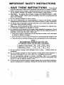
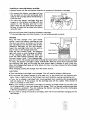
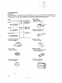
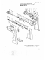
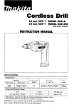
. :..:
.
. __..._
. ,..,.:f,
L.
'
:
...' !
: ..; ...,:.. ...
.1
. .....
.. .
.........
..".
, ., ,
,,._..
. ..
,. .... !.
.
"
Equipped with Keyless Chuck and Electric Brake
MODEL 6 O l l D
MODEL 6011DW
Wlth Fast Charger
INSTRUCTION MANUAL
SPECIFICATIONS
9
Model 8011D
Capacities
No load speed IRPMI
Steel
Wood
Wood screw
Machine screw
10mm
1318")
21mm
113/16'J
5.8mmx75mm
115164" x 2-5/16")
6mm
115/64"l
Voltage
Charging time
12 v
1 HI.
I
High
- 1'350
Dimensions
11 x W x HJ
Net
weight
270 mm x 58 mm x 262 mm
110-5/8" x 2-114" x 10-5/16"1
1.9 kg
14.2 lbsl
Low
- 450
Input
A.C. only 50 HZ - 60 Hz
I
I
Manufacturer reserves the right to change specifications without notice.
Note: Specifications may differ from country to country.
Output
D.C. 9.6 V. 12 V
IMPORTANT
SAFETY INSTRUCTIONS
(For All Tools)
WARNING: WHEN USING ELECTRIC TOOLS, BASIC SAFETY
PRECAUTIONS SHOULD ALWAYS BE FOLLOWED TO REDUCE
THE RISK OF FIRE, ELECTRIC SHOCK, AND PERSONAL
INJURY, INCLUDING THE FOLLOWING:
READ ALL INSTRUCTIONS.
1. KEEP WORK AREA CLEAN. Cluttered areas and benches invite injuries.
2. CONSIDER WORK AREA ENVIRONMENT. Don't use power tools in damp
or wet locations. Keep work area well lit. Don't expose power tools t o rain.
Don't use tool in presence of flammable liquids or gases.
3. KEEP CHILDREN AWAY. All visitors should be kept away from work area.
Don't let visitors contact tool or extension cord.
4. STORE IDLE TOOLS. When not in use, tools should be stored in dry, and high
or locked-up place
out of reach of children.
-
5. DON'T FORCE TOOL. It will do the job better and safer at the rate for which
it was intended.
6. USE RIGHT TOOL. Don't force small tool or attachment to do the job of a
heavy-duty tool. Don't use tool for purpose not intended.
7 . DRESS PROPERLY. Don't wear loose clothing or jewelry. They can be caught
in moving parts. Rubber gloves and non-skid footwear are recommended
when working outdoors. Wear protective hair covering t o contain long hair.
8.USE SAFETY GLASSES. Also use face or dust mask if cutting operation is
dusty.
9.DON'T ABUSE CORD. Never carry tool by cord or yank it t o disconnect from
receptacle. Keep cord from heat, oil, and sharp edges.
IO. SECURE WORK.
Use clamps or a vise t o hold work. It's safer than using
your hand and it frees both hands to operate tool.
11. DON'T OVERREACH. Keep proper footing and balance at all times.
12. MAINTAIN TOOLS WITH CARE. Keep tools sharp and clean for better and
safer performance. Follow instructions for lubricating and changing accessories. Inspect tool cords periodically and if damaged, have repaired by authorized service facility. Inspect extension cords periodically and replace if
damaged. Keep handles dry, clean, and free from oil and grease.
13. DISCONNECT TOOLS. When not in use, before servicing, and when changing accessories, such as blades, bits, cutters.
14. REMOVE ADJUSTING KEYS AND WRENCHES. Form habit of checking to
15.
16.
17.
18.
19.
see that keys and adjusting wrenches are removed from tool before turning
it on.
AVOID UNINTENTIONAL STARTING. Don't carry plugged-in tool with finger
on switch. Be sure switch is OFF when plugging in.
OUTDOOR USE EXTENSION CORDS. When tool is used outdoors, use only
extension cords intended for use outdoors and so marked.
STAY ALERT. Watch what you are doing, use common sense. Don't operate
tool when you are tired.
CHECK DAMAGED PARTS. Before further use of the tool, a guard or other
part that is damaged should be carefully checked t o determine that it will
operate properly and perform its intended function. Check for alignment of
moving parts, bjnding of moving parts, breakage of parts, mounting, and
any other conditions that may affect its operation. A guard or other part
that is damaged should be properly repaired or replaced by an authorized
service center unless otherwise indicated elsewhere in this instruction
manual. Have defective switches replaced by authorized service center. Don't
use tool if switch does not turn it on and off.
GUARD AGAINST ELECTRIC SHOCK. Prevent body contact with grounded
surfaces. For example; pipes, radiators, ranges, refrigerator enclosures.
20. REPLACEMENT PARTS. When servicing, use only identical replacement parts.
VOLTAGE WARNING: Before connecting the tool t o a power source (receptacle,
outlet, etc.) be sure the voltage supplied is the same as that specified on the
nameplate of the tool. A power source with voltage greater than that specified
for the tool can result in SERIOUS INJURY t o the user - as well as damage t o
the tool. If in doubt, DO NOT PLUG IN THE TOOL. Using a power source with
voltage less than the nameplate rating is harmful t o the motor.
3
IMPORTANT SAFETY INSTRUCTIONS
I.
SAVE THESE INSTRUCTIONS
- This manual
contains important safety and operating instructions for battery charger.
2. Before using battery charger, read all instructions and cautionary markings
on (1) battery charger, ( 2 ) battery, and (3)product using battery.
3. CAUTION - To reduce risk of injury, charge only MAKITA Battery 1200,
1210,9000 or 9100.Other ty,pes of batteries may burst causing personal
injury and damage.
4. Do not expose charger t o rain or snow.
5. Use of an attachment not recommended or sold by the battery charger
manufacturer may result in a risk of fire, electric shock, or injury t o persons.
6.To reduce risk of damage t o electric plug and cord, pull by plug rather than
cord when disconnecting charger.
7. Make sure cord is located so that it will not be stepped on, tripped over,
or otherwise subjected t o damage or stress.
8.A n extension cord should not be used unless absolutely necessary. Use of
improper extension cord could result in a risk of fire and electric shock. If
extension cord must be used, make sure:
a. That pins on plug of extension cord are the same number, size, and shape
as those of plug on charger;
b. That extension cord is properly wired and in good electrical condition; and
c. That wire size is at least as large as the one specified in the table below.
TABLE 1
RECOMMENDED MINIMUM AWG SIZE FOR
EXTENSION CORDS FOR BATTERY CHARGERS
Length of Cord (Feet)
25
50
AWG Size of Cord
18
18
100
18
150
16
4
. . .
..
.. . .. . .
...... .-.
.. .,...._...
.
..
...., ... .
...
. .: .... ...
. .- ..:' :
......
.. .. ,.
I .
, r .
'
! _ . _ . . I
,,
..,r..
!
ADDITIONAL SAFETY RULES
FOR CHARGER & BATTERY CARTRIDGE
1. Do not charge Battery Cartridge when temperature is BELOW 10°C (5OOF)
or ABOVE 4OoC ( 1 0 4 O F ) .
2. Do not attempt t o use a step-up transformer, an engine generator or DC power
receptacle.
3. Do not allow anything to cover or clog the charger vents.
4.Always cover the battery terminals w i t h the battery cover when the battery
cartridge is not used.
5. A battery short can cause a large current flow, overheating, possible burns
and even a breakdown.
(1) Do not touch the terminals w i t h any conductive material.
(2) Avoid storing battery cartridge in a container with other metal objects such
as nails, coins, etc.
(3) Do not expose battery cartridge t o water or rain.
6. Do not store the tool and Battery Cartridge in locations where the temperature may reach or exceed 5OoC (122OF).
7. Do not incinerate the Battery Cartridge even if it is severely damaged or is
completely worn out. The battery cartridge can explode in a fire.
ADDITIONAL SAFETY RULES
1. Be aware that this tool is always in an operating condition, because it does
not have t o be plugged into an electrical outlet.
2. Always be sure you have a firm footing.
Be sure no one is below when using the tool in high locations.
3. Hold the tool firmly.
4.Keep hands away from rotating parts.
5. When drilling into walls, floors or wherever "live" electrical wires may be
encountered, DO NOT TOUCH ANY METAL PARTS OF THE TOOL!
Hold the tool only by the insulated grasping surfaces t o prevent electric shock
if you drill into a "live" wire.
6. Do not leave the tool running. Operate the tool only when hand-held.
7. Do not touch the drill bit or the workpiece immediately after operation: they
may be extremely hot and could burn your skin.
SAVE THESE INSTRUCTIONS.
5
Installing or removing battery cartridge
*Always switch off the tool before insertion or removal of the battery cartridge.
*To remove the battery cartridge, pull out
the set plate on the tool and grasp both
sides of the cartridge while withdrawing it
from the tool.
*To insert the battery cartridge, align the
tongue on the battery cartridge with the
groove in the housing and slip it into
place. Snap the set plate back into place.
Be sure to close the set plate fully before
using the tool.
I
Set plete
Do not use force when inserting the battery cartridge.
If the cartridge does not slide in easily, it is not being inserted correctly.
Charging
Plug the fast charger into your power
source. Insert the battery cartridge so that
the plus and minus terminals on the battery cartridge are on the same sides as their
respective markings on the fast charger.
Insert the cartridge fully into the port so
t h a t it rests on the charger port floor.
Press the start button (red). The charging
light will come on and charging will begin.
If the charging light does not come on,
press the reset button (yellow) first, then
the start button (red). If the charging light
goes out within 10 seconds even after pressing the reset button and start button a couple
of times, the battery cartridge i s dead. (CAUTION: Wait for more than 5 seconds after
the charging light goes out to press the reset button again.) Replace it with a new one.
When the charging light goes out after about one hour, you may remove the fully charged
battery cartridge.
After charging, unplug the charger from the power source.
CAUTION :
Your new battery cartridge i s not charged. You will need to charge it before use.
Do not keep the button pressed in with tape, etc. or the circuit will not function properly. Also, a malfunction of the charger may result possibly causing overheating, etc.
0 If you try to charge a cartridge from a just-operated tool, sometimes the charging light
will not come on. If this occurs, l e t the cartridge cool off for a while. Then reinsert it
and try to charge it once more.
When you charge a new battery cartridge or a battery cartridge which has not been used
for a long period, it may not accept a full charge. This i s a normal condition and does
not indicate a problem. You can recharge the battery cartridge fully after discharging
it almost completely a couple or times.
If you wish to charge two battery cartridges, allow 15 minutes between chargings on the
fast charger.
6
..
I
Installing or removing driver bit or dirll bit
CAUTION :
Always be sure that the tool is switched off and the battery cartridge is removed before
installing or removing the bit.
Hold the ring and turn the sleeve counterclockwise to open the chuck jaws. Place
the bit in the chuck as far as it will go.
Hold the ring firmly and turn the sleeve
clockwise to tighten the chuck.
To remove the bit, hold the ring and turn
the sleeve counterclockwise.
Storage of driver bit
When not using the driver bit, keep it in the storage cavity on the tool.
Switch action
Tool speed is increased by increasing pressure on the trigger. To start the tool,
simply pull the trigger. Rlelease the trigger
to stop.
CAUTION :
Before inserting the battery cartridge into the tool, always check to see that the trigger
switch actuates properly and returns to the "OFF" position when released.
Reversing switch action
This tool has a reversing switch to change
the direction -of rotation. Slide the reversing switch to the right for clockwise rotation or to the left for counterclockwise.
Reversing
CAUTION:
Always check the direction of rotation before operation.
*Use the reversing switch only when the tool comes to a complete stop. Changing the
direction of rotation before the tool stops may ruin the tool.
7
Speed change
To change the speed, turn the speed change
knob 180' while the tool is running. Be
sure that the speed change knob is turned
to the correct speed setting before you
begin operation. See arrow indication. Use
the right speed for the job.
0 - 450 Rlmin.
Speed change knob
o - 1,350 Rlmin.
Adjusting fastening torque
The fastening torque can be adjusted in
Adjusting ring Pointer
six stages by turning the adjusting ring
\
so that the pointer on the adjusting ring
points to a number on the tool body. The
fastening torque is minimum ,when the
pointer points so the number 1 and maximum when it points to the -8- marking.
The clutch will slip a t varying torque levels
when the pointer is set a t the numbers 1
to 5. The crutch is designed not to slip a t
the - 8 marking.
I
Before actual operation, drive a trial screw into your material or a piece of duplicate
material to determine which torque level i s required for a particular application.
1-
NOTE :
The adjusting ring cannot be locked with the pointer positioned half-way between the
numbers.
Screwdriving operation
Place the point of the driver bit in the
screw head and apply pressure to the tool.
Start the tool slowly and then increase the
speed gradually. Release the trigger as soon
as the clutch cuts in.
I
When driving wood screws, predrill Pilot
holes to make driving easier and to prevent splitting of the workpiece. See the
chart.
Nominal diameter
of wood screw (mm)
Recommended size
O f pilot hole (mm)
3.1(i/8*)
3.5 (9/64')
3.8 (5/32")
4.5(11164")
4.8 (3/16"1
5.1 (13/64")
2.0- 2.2(5/64" - 3/32")
2.5- 2.8 (3/32"- 7/64")
2.9- 3.2 (7/64"-1/8')
3.1 - 3.4 (118'- 9/64")
3.3- 3.6(118'- 9/63")
5.5 (7/32")
5.8 (15/64"1
3.7- 3.9 (9/64"- 5/32")
4.0 - 4.2(5/32"- 11/64")
2.2- 2.5 (3/32"- 3/32")
Drilling operation
Drilling in wood
When drilling in wood, best results are obtained with wood drills equipped with a guide
screw. The guide screw makes drilling easier by pulling the bit into the workpiece.
Drilling in metal
To prevent the bit from slipping when starting a hole, make an indentation with a
centerpunch and hammer a t the point to be drilled. Place the point of the bit in the
indentation and start drilling.
Use a cutting lubricant when drilling metals. The exceptions are iron and brass which
should be drilled dry.
CAUTION :
*Pressing excessively on the tool will not speed up the drilling. In fact, this excessive pressure will only serve to damage the tip of your bit, decrease the tool performance and
shorten the service life of the tool.
*There is a tremendous force exerted on the tool/bit at the time of hole breakthrough.
Hold the tool firmly and exert care when the bit begins to break through the workpiece.
A stuck bit can be removed simply by setting the reversing switch to reverse rotation in
order to back out. However, the tool may back out abruptly if you do not hold it firmly.
Always secure small workpieces in a vise or similar hold-down device.
MA1NTENANCE
CAUTION :
Always be sure that the tool is switched off and the battery cartridge is removed before
attempting to perform inspection or maintenance.
To maintain product SAFETY and RELIABILITY, repairs, maintenance or adjustment
should be performed by Makita Authorized or Factory Service Centers, always using
Makita replacement parts.
9
ACC ESSOR IES
CAUTION :
These accessories or attachments are recommended for use with your Makita tool specified in this
manual. The use of any other accessories or attachments might present a risk of injury to persons.
The accessories or attachments should be used only in the proper and intended manner.
0
Bits
I
Size
I
Part NO.
Phillips
Fast charger
Model DCl290
Part No. 113119-108
Slotted
78401 1-OA
Square drill bit
Battery cartridge 1210
Part No. 632277-5
784606-0A
Rubber ped assembly
Part No. 123001-2
Battery cover
Part No. 414938-7
W o o l bonnet
Part No. 743401-6
Battery holster
Holster holds extra battery.
Part No. 823033-3C
Foam polishing pad
Part No. 743023-2
Plastic carrying case
Part No. 824401-6
10
Feb-04-'92
CORDLESS DRIVER DRILL
US
I
Model 6011D
11
F.h-M-'S?
MODEL 8OllD
ITEM
NO.
NO.
USED
AtD
DESCRIPTION
MA(
1
7
2
2
3
4
5
1
2
1
28
29
2
30
7
8
1
1
31
32
33
34
35
36
S
I
10
11
1
1
12
13
1
1
14
15
1
1
I8
:!I
r.
17
1
24
1
21
UE
25
28
27
8
i
I
1: 1 ;
US
DESCRIPTION
I
1
1
1
4
I
1
1
1
1
1
37
38
1
1
1
39
40
41
42
43
U
45
46
1
1
1
1
1
1
1
47
I
I
- b8
1
Nota: Tho switch and other pan S ~ ~ C I Imry
I Cdifler
~ I Ilrom
O ~country
S
Io country.
r
I
MAKlTA LIMlTEDONE YEAR WARRANTY
Warranty Policy
IN NO EVENT SHALL MAKITA BE LIABLE FOR ANY INDIRECT. INCIDENTAL OR CONSEQUENTIAL DAMAGES FROM THE SALT OR USE O F THE PRODUCT. THIS DISCLAIMER
APPLIES BOTH DURING AND AFTER THETERM O F THIS WARRANTY.
MAKITA DISCLAIMS L l A B l L l N FOR ANY IMPLIED WARRANTIES. INCLUDING IMPLIED
WARRANTIES O F "MERCHANTABILITY" AND "FITNESS FOR A S P u l l F l C PURPOSE."
AFTER THE ONE-YEAR TERM O F THIS WARRANTY.
Makita Corporation of America
2650 Gainesville Hwy., Buford, GA 30518
.-
883802
- 069
PRINTED IN USA
1992 3 4D
-
-