1
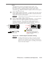
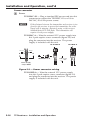
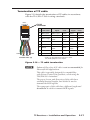
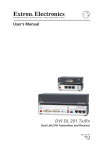
User’s Manual C Do not connect this device to a computer data or telecommunications network TP Receivers Family High Resolution Video, Composite Video, and Stereo Audio Twisted Pair Cable Transmission Products 68-547-02 Rev. L 01 10 Precautions Safety Instructions • English This symbol is intended to alert the user of important operating and maintenance (servicing) instructions in the literature provided with the equipment. This symbol is intended to alert the user of the presence of uninsulated dangerous voltage within the product’s enclosure that may present a risk of electric shock. Caution Read Instructions • Read and understand all safety and operating instructions before using the equipment. Retain Instructions • The safety instructions should be kept for future reference. Follow Warnings • Follow all warnings and instructions marked on the equipment or in the user information. Avoid Attachments • Do not use tools or attachments that are not recommended by the equipment manufacturer because they may be hazardous. Consignes de Sécurité • Français Ce symbole sert à avertir l’utilisateur que la documentation fournie avec le matériel contient des instructions importantes concernant l’exploitation et la maintenance (réparation). Ce symbole sert à avertir l’utilisateur de la présence dans le boîtier de l’appareil de tensions dangereuses non isolées posant des risques d’électrocution. Attention Lire les instructions• Prendre connaissance de toutes les consignes de sécurité et d’exploitation avant d’utiliser le matériel. Conserver les instructions• Ranger les consignes de sécurité afin de pouvoir les consulter à l’avenir. Respecter les avertissements • Observer tous les avertissements et consignes marqués sur le matériel ou présentés dans la documentation utilisateur. Eviter les pièces de fixation • Ne pas utiliser de pièces de fixation ni d’outils non recommandés par le fabricant du matériel car cela risquerait de poser certains dangers. Sicherheitsanleitungen • Deutsch Dieses Symbol soll dem Benutzer in der im Lieferumfang enthaltenen Dokumentation besonders wichtige Hinweise zur Bedienung und Wartung (Instandhaltung) geben. Dieses Symbol soll den Benutzer darauf aufmerksam machen, daß im Inneren des Gehäuses dieses Produktes gefährliche Spannungen, die nicht isoliert sind und die einen elektrischen Schock verursachen können, herrschen. Achtung Lesen der Anleitungen • Bevor Sie das Gerät zum ersten Mal verwenden, sollten Sie alle Sicherheits-und Bedienungsanleitungen genau durchlesen und verstehen. Aufbewahren der Anleitungen • Die Hinweise zur elektrischen Sicherheit des Produktes sollten Sie aufbewahren, damit Sie im Bedarfsfall darauf zurückgreifen können. Befolgen der Warnhinweise • Befolgen Sie alle Warnhinweise und Anleitungen auf dem Gerät oder in der Benutzerdokumentation. Keine Zusatzgeräte • Verwenden Sie keine Werkzeuge oder Zusatzgeräte, die nicht ausdrücklich vom Hersteller empfohlen wurden, da diese eine Gefahrenquelle darstellen können. Instrucciones de seguridad • Español Este símbolo se utiliza para advertir al usuario sobre instrucciones importantes de operación y mantenimiento (o cambio de partes) que se desean destacar en el contenido de la documentación suministrada con los equipos. Este símbolo se utiliza para advertir al usuario sobre la presencia de elementos con voltaje peligroso sin protección aislante, que puedan encontrarse dentro de la caja o alojamiento del producto, y que puedan representar riesgo de electrocución. Precaucion Leer las instrucciones • Leer y analizar todas las instrucciones de operación y seguridad, antes de usar el equipo. Conservar las instrucciones • Conservar las instrucciones de seguridad para futura consulta. Obedecer las advertencias • Todas las advertencias e instrucciones marcadas en el equipo o en la documentación del usuario, deben ser obedecidas. Evitar el uso de accesorios • No usar herramientas o accesorios que no sean especificamente recomendados por el fabricante, ya que podrian implicar riesgos. Warning Power sources • This equipment should be operated only from the power source indicated on the product. This equipment is intended to be used with a main power system with a grounded (neutral) conductor. The third (grounding) pin is a safety feature, do not attempt to bypass or disable it. Power disconnection • To remove power from the equipment safely, remove all power cords from the rear of the equipment, or the desktop power module (if detachable), or from the power source receptacle (wall plug). Power cord protection • Power cords should be routed so that they are not likely to be stepped on or pinched by items placed upon or against them. Servicing • Refer all servicing to qualified service personnel. There are no userserviceable parts inside. To prevent the risk of shock, do not attempt to service this equipment yourself because opening or removing covers may expose you to dangerous voltage or other hazards. Slots and openings • If the equipment has slots or holes in the enclosure, these are provided to prevent overheating of sensitive components inside. These openings must never be blocked by other objects. Lithium battery • There is a danger of explosion if battery is incorrectly replaced. Replace it only with the same or equivalent type recommended by the manufacturer. Dispose of used batteries according to the manufacturer’s instructions. Avertissement Alimentations• Ne faire fonctionner ce matériel qu’avec la source d’alimentation indiquée sur l’appareil. Ce matériel doit être utilisé avec une alimentation principale comportant un fil de terre (neutre). Le troisième contact (de mise à la terre) constitue un dispositif de sécurité : n’essayez pas de la contourner ni de la désactiver. Déconnexion de l’alimentation• Pour mettre le matériel hors tension sans danger, déconnectez tous les cordons d’alimentation de l’arrière de l’appareil ou du module d’alimentation de bureau (s’il est amovible) ou encore de la prise secteur. Protection du cordon d’alimentation • Acheminer les cordons d’alimentation de manière à ce que personne ne risque de marcher dessus et à ce qu’ils ne soient pas écrasés ou pincés par des objets. Réparation-maintenance • Faire exécuter toutes les interventions de réparationmaintenance par un technicien qualifié. Aucun des éléments internes ne peut être réparé par l’utilisateur. Afin d’éviter tout danger d’électrocution, l’utilisateur ne doit pas essayer de procéder lui-même à ces opérations car l’ouverture ou le retrait des couvercles risquent de l’exposer à de hautes tensions et autres dangers. Fentes et orifices • Si le boîtier de l’appareil comporte des fentes ou des orifices, ceux-ci servent à empêcher les composants internes sensibles de surchauffer. Ces ouvertures ne doivent jamais être bloquées par des objets. Lithium Batterie • Il a danger d’explosion s’ll y a remplacment incorrect de la batterie. Remplacer uniquement avec une batterie du meme type ou d’un ype equivalent recommande par le constructeur. Mettre au reut les batteries usagees conformement aux instructions du fabricant. Vorsicht Stromquellen • Dieses Gerät sollte nur über die auf dem Produkt angegebene Stromquelle betrieben werden. Dieses Gerät wurde für eine Verwendung mit einer Hauptstromleitung mit einem geerdeten (neutralen) Leiter konzipiert. Der dritte Kontakt ist für einen Erdanschluß, und stellt eine Sicherheitsfunktion dar. Diese sollte nicht umgangen oder außer Betrieb gesetzt werden. Stromunterbrechung • Um das Gerät auf sichere Weise vom Netz zu trennen, sollten Sie alle Netzkabel aus der Rückseite des Gerätes, aus der externen Stomversorgung (falls dies möglich ist) oder aus der Wandsteckdose ziehen. Schutz des Netzkabels • Netzkabel sollten stets so verlegt werden, daß sie nicht im Weg liegen und niemand darauf treten kann oder Objekte darauf- oder unmittelbar dagegengestellt werden können. Wartung • Alle Wartungsmaßnahmen sollten nur von qualifiziertem Servicepersonal durchgeführt werden. Die internen Komponenten des Gerätes sind wartungsfrei. Zur Vermeidung eines elektrischen Schocks versuchen Sie in keinem Fall, dieses Gerät selbst öffnen, da beim Entfernen der Abdeckungen die Gefahr eines elektrischen Schlags und/oder andere Gefahren bestehen. Schlitze und Öffnungen • Wenn das Gerät Schlitze oder Löcher im Gehäuse aufweist, dienen diese zur Vermeidung einer Überhitzung der empfindlichen Teile im Inneren. Diese Öffnungen dürfen niemals von anderen Objekten blockiert werden. Litium-Batterie • Explosionsgefahr, falls die Batterie nicht richtig ersetzt wird. Ersetzen Sie verbrauchte Batterien nur durch den gleichen oder einen vergleichbaren Batterietyp, der auch vom Hersteller empfohlen wird. Entsorgen Sie verbrauchte Batterien bitte gemäß den Herstelleranweisungen. Advertencia Alimentación eléctrica • Este equipo debe conectarse únicamente a la fuente/tipo de alimentación eléctrica indicada en el mismo. La alimentación eléctrica de este equipo debe provenir de un sistema de distribución general con conductor neutro a tierra. La tercera pata (puesta a tierra) es una medida de seguridad, no puentearia ni eliminaria. Desconexión de alimentación eléctrica • Para desconectar con seguridad la acometida de alimentación eléctrica al equipo, desenchufar todos los cables de alimentación en el panel trasero del equipo, o desenchufar el módulo de alimentación (si fuera independiente), o desenchufar el cable del receptáculo de la pared. Protección del cables de alimentación • Los cables de alimentación eléctrica se deben instalar en lugares donde no sean pisados ni apretados por objetos que se puedan apoyar sobre ellos. Reparaciones/mantenimiento • Solicitar siempre los servicios técnicos de personal calificado. En el interior no hay partes a las que el usuario deba acceder. Para evitar riesgo de electrocución, no intentar personalmente la reparación/mantenimiento de este equipo, ya que al abrir o extraer las tapas puede quedar expuesto a voltajes peligrosos u otros riesgos. Ranuras y aberturas • Si el equipo posee ranuras o orificios en su caja/alojamiento, es para evitar el sobrecalientamiento de componentes internos sensibles. Estas aberturas nunca se deben obstruir con otros objetos. Batería de litio • Existe riesgo de explosión si esta batería se coloca en la posición incorrecta. Cambiar esta batería únicamente con el mismo tipo (o su equivalente) recomendado por el fabricante. Desachar las baterías usadas siguiendo las instrucciones del fabricante. Precautions, cont’d 安全须知 • 中文 警告 这个符号提示用户该设备用户手册中 有重要的操作和维护说明。 电源 • 该 设 备 只 能 使 用 产 品 上 标 明 的 电 源 。 设 备 必须使用有地线的供电系统供电。 第三条线 (地线)是安全设施,不能不用或跳过。 这个符号警告用户该设备机壳内有暴 拔掉电源 • 为安全地从设备拔掉电源,请拔掉所有设备后 或桌面电源的电源线,或任何接到市电系统的电源线。 露的危险电压,有触电危险。 电源线保护 • 妥善布线, 避免被踩踏,或重物挤压。 注意 阅读说明书 • 用 户 使 用 该 设 备 前 必 须 阅 读 并 理 解所有安全和使用说明。 保存说明书 • 用户应保存安全说明书以备将来使 用。 遵守警告 • 用户应遵守产品和用户指南上的所有安 全和操作说明。 维护 • 所有维修必须由认证的维修人员进行。 设备内部 没有用户可以更换的零件。为避免出现触电危险不要自 己试图打开设备盖子维修该设备。 通风孔 • 有些设备机壳上有通风槽或孔,它们是用来防止 机内敏感元件过热。 不要用任何东西挡住通风孔。 锂电池 • 不正确的更换电池会有爆炸的危险。 必须使用 与厂家推荐的相同或相近型号的电池。 按照生产厂的 建议处理废弃电池。 避免追加 • 不要使用该产品厂商没有推荐的工具或 追加设备,以避免危险。 FCC Class A Notice This equipment has been tested and found to comply with the limits for a Class A digital device, pursuant to part 15 of the FCC Rules. Operation is subject to the following two conditions: (1) this device may not cause harmful interference, and (2) this device must accept any interference received, including interference that may cause undesired operation. The Class A limits are designed to provide reasonable protection against harmful interference when the equipment is operated in a commercial environment. This equipment generates, uses, and can radiate radio frequency energy and, if not installed and used in accordance with the instruction manual, may cause harmful interference to radio communications. Operation of this equipment in a residential area is likely to cause harmful interference, in which case the user will be required to correct the interference at his own expense. N This unit was tested with shielded cables on the peripheral devices. Shielded cables must be used with the unit to ensure compliance with FCC emissions limits. Table of Contents Chapter One • Introduction ................................................... 1-1 About the TP Receivers ...................................................... 1-2 Features ...................................................................................... 1-4 TP R BNC A receiver .............................................................. 1-4 TP R BNC AV receiver ............................................................ 1-5 TP R 15HD A receiver ............................................................ 1-5 Chapter Two • Installation and Operation .................. 2-1 Installation Overview ......................................................... 2-2 Video jumpers ....................................................................... 2-4 Video DIP switch .................................................................... 2-5 Audio jumpers ....................................................................... 2-5 Mounting the receiver .......................................................... 2-7 UL guidelines for rack mounting ....................................... 2-7 Rack mounting (TP R BNC A, TP R BNC AV, TP R 15HD A) .. 2-8 Furniture mounting ........................................................ 2-10 Projector mounting ......................................................... 2-11 Rear panel features and cabling ........................................ 2-12 Transmitted signal cabling .............................................. 2-12 Output cabling ................................................................ 2-13 Computer video .......................................................... 2-13 Composite video ......................................................... 2-14 Audio .......................................................................... 2-15 Power connector ............................................................. 2-16 Termination of TP cable ...................................................... 2-17 Cable testing ................................................................... 2-18 Equalizing pair skew ....................................................... 2-18 Front Panel Controls and Indicators ......................... 2-20 Troubleshooting ................................................................... 2-21 If the image does not appear ............................................. 2-21 If the image is not displayed correctly ............................... 2-22 If the receiver Manual/Auto LED flashes ........................... 2-22 Appendix • Specifications, ..................................................... A-1 Accessories, and Part Numbers ........................................... A-1 Included Parts ......................................................................... A-6 Extron Accessories ............................................................... A-7 TP Receivers • Table of Contents i Table of Contents, cont’d All trademarks mentioned in this manual are the properties of their respective owners. 68-547-02 Rev. L 01 10 ii TP Receivers • Table of Contents TP Receivers 1 Chapter One Introduction About the TP Receivers Features Introduction, Introductioncont’d About the TP Receivers The TP R BNC A, TP R BNC AV, and TP R 15HD A are Extron Twisted Pair (TP) receivers that receive transmissions of RGB video, component video, S-video, composite video, and stereo audio over Extron Enhanced Skew-Free™ A/V UTP cable or standard Category (CAT) 5 unshielded twisted pair (UTP), shielded twisted pair (STP), or foil shielded twisted pair (FTP) cable. Standard transmission distances are shown in the following tables. Minimum reliable transmission distance for the TP R BNC A and TP R BNC AV is 25 feet. The TP R 15HD A provides reliable reception and high quality video output without minimum distance limitations. Maximum distance is determined by the output frequency and resolution. The following table specifies recommended maximum transmission distances using Extron Enhanced Skew-Free A/V UTP cable or UTP CAT 5 cable, terminated with CAT 6, or at least CAT 5e, rated connectors. N The TP units are designed for and perform best with Enhanced Skew-Free A/V cable terminated in accordance with the TIA/EIA T 568 A wiring standard. Cables terminated on site should be tested before use to ensure they comply with Category 5/5e/6 specifications. Recommended transmission ranges at 60 Hz, TP R 15HD A Maximum range (High Quality) Video format Component, S-video, Composite video and audio 640 x 480 800 x 600 1024 x 768 1280 x 960 1280 x 1024 1360 x 765 1365 x 768 1366 x 768 1440 x 900 1400 x 1050 1600 x 1200 1920 x 1200 N 1-2 Maximum range (Variable Quality) 700 feet (213 m) 800 feet (243 m) 500 feet (152 m) 400 feet (120 m) 300 feet (90 m) 300 feet (90 m) 250 feet (76 m) 250 feet (76 m) 250 feet (76 m) 250 feet (76 m) 250 feet (76 m) 250 feet (76 m) 200 feet (61 m) 200 feet (61 m) 550 feet (168 m) 450 feet (137 m) 400 feet (120 m) 350 feet (106 m) 300 feet (90 m) 300 feet (90 m) 300 feet (90 m) 300 feet (90 m) 300 feet (90 m) 300 feet (90 m) 250 feet (76 m) 250 feet (76 m) While it is possible to exceed recommended distances, image quality may be reduced. TP Receivers • Introduction Recommended transmission ranges at 60 Hz, TP R BNC A and TP R BNC AV Video format Component, S-video, Composite video and audio 640 x 480 800 x 600 1024 x 768 1280 x 960 1280 x 1024 1360 x 765 1365 x 768 1366 x 768 1440 x 900 1400 x 1050 1600 x 1200 1920 x 1200 Maximum range (High Quality) Maximum range (Variable Quality) 1000 feet (304 m) 1050 feet (320 m) 1000 feet (304 m) 800 feet (243 m) 600 feet (182 m) 450 feet (137 m) 400 feet (120 m) 400 feet (120 m) 400 feet (120 m) 400 feet (120 m) 350 feet (106 m) 350 feet (106 m) 300 feet (90 m) 300 feet (90 m) 1050 feet (320 m) 900 feet (274 m) 700 feet (213 m) 600 feet (182 m) 500 feet (152 m) 500 feet (152 m) 500 feet (152 m) 500 feet (152 m) 450 feet (137 m) 450 feet (137 m) 400 feet (120 m) 400 feet (120 m) The TP receivers only receive signals transmitted by Extron TP transmitters. This user manual documents installation, features, and operation of the TP receivers only. For information about the TP transmitters, refer to the TP Transmitters Family User’s Manual, TP T 15HD 45 and TP T A 45 Manual, or the VTT001/TR001 Transmitter and Receiver Manual, as applicable, which accompany the transmitters. TP Receivers • Introduction 1-3 Introduction, cont’d Features All Extron TP receivers provide the following features: Audio output — Provides unbalanced (left/right) audio on RCA connectors, and balanced or unbalanced audio on 3.5 mm, 5-pole captive screw connectors. Level control — Allows manual control of image brightness. Peaking control — Allows manual control of image sharpness. TP R BNC A receiver The TP R BNC A receiver has the following features: Video output — Provides RGBHV, RGBS, or RGsB video on 5 BNC connectors. RJ-45 connector — Allows attachment to an Extron TP transmitter. Cable length compensation — Compensates for long cable runs automatically or manually. Mounting — 1-4 Mounts in a rack with an Extron Universal Rack Shelf Kit for 9.5 inch deep products (part #60-190-01) or Basic Rack Shelf for 9.5 inch deep products (part #60-604-02). Mounts to a projector mounting bracket with Extron Pole Mount Kits PMK 200 (part #70-077-04) or PMK 100 (part #70-217-01). Mounts under or through furniture with an Extron Under‑Desk Mounting Kit (part #70-077-01) or Through‑Desk Mounting Kit (part #70-077-02). TP Receivers • Introduction TP R BNC AV receiver The TP R BNC AV receiver has the following features: Video output — Provides RGBHV, RGBS, or RGsB video on 5 BNC connectors, and composite video on 1 BNC connector. RJ-45 connector — Allows attachment to an Extron TP transmitter. One connector is for computer input and one is for A/V input. Cable length compensation — Provides selection between automatic or manual compensation for long cable runs. Mounting — Mounts in a rack with an Extron Universal Rack Shelf Kit for 9.5 inch deep products (part #60-190-01) or Basic Rack Shelf for 9.5 inch deep products (part #60-604-02). Mounts to a projector mounting bracket with Extron Pole Mount Kits PMK 200 (part #70-077-04) or PMK 100 (part #70-217-01). Mounts under or through furniture with an Extron Under‑Desk Mounting Kit (part #70-077-01) or Through‑Desk Mounting Kit (part #70-077-02). TP R 15HD A receiver The TP R 15HD A receiver has the following features: Video output — Provides RGBHV, RGBS, and RGsB on a 15-pin HD connector. With an optional SY 15 HD-RGBHV cable, the receiver can output component video (bi-level only), S-video, or composite video. RJ-45 connector — Allows attachment to an Extron TP transmitter. Mounting — Mounts in an Extron Rack Shelf Kit for 3.5 inch deep products (part #60-190-20), Basic Rack Shelf kit for 3.5 inch deep products (part #60-604-20), a Universal Rack Shelf Kit for 9.5 inch deep products (part #60-190-01) or Basic Rack Shelf for 9.5 inch deep products (part #60-604-02), Basic Rack Shelf for 6 inch deep products (part #60-604-11), Universal Rack Shelf Kit for 6 inch deep products (part #60-190-10). Mounts under furniture or to a projector bracket with Extron optional mounting kits (part #70-212-01, furniture, or #70-217-01, projector). TP Receivers • Introduction 1-5 Introduction, cont’d This page intentionally left blank. 1-6 TP Receivers • Introduction TP Receivers 2 Chapter Two Installation and Operation Installation Overview Front Panel Controls and Indicators Troubleshooting Installation Installation and andOperation Operation, cont’d Installation Overview To install and set up a TP receiver and the associated TP transmitter(s) for operation, perform the following steps: 1 Disconnect power from all of the equipment, including the video source, (such as computers or DVD players), the transmitter, receiver, and output displays. 2 For component, S-video, or composite video, ensure the internal jumpers (TP R BNC A and TP R BNC AV) or external DIP switch (TP R 15HD A) are in the correct position. See Video jumpers or Video DIP switch in this chapter. 3 TP R BNC AV Only — If required, configure the audio jumpers to make the receiver compatible with unmodified TP transmitters. See Audio jumpers in this chapter. N The TP R BNC AV is a redesigned (modified) receiver. Audio jumpers configure the audio portion of the composite video TP link to work with the similarly redesigned TP T 15HD AV transmitter or with older, unmodified transmitters. Redesigned receivers and transmitters have an identifying label. 4 Mount the receiver in a rack (the TP R 15HD A can be mounted in a standard rack), under a desk or podium, in a desk or table (all except TP R 15HD A), or on a projector bracket. See Mounting the receiver in this chapter. 5 Connect the cable(s) between the TP transmitter(s) and the receiver. See Transmitted signal cabling in this chapter and refer to the TP Transmitters Family User’s Manual, part #68-546-03, or the TP T 15HD 45 and TP T A 45 Manual, #68-924-01, as applicable. 6 Connect the output cables. See Output cabling in this chapter. 7 Configure the TP transmitter(s). Refer to the TP Transmitters Family User’s Manual, part #68-546-03, or the TP T 15HD 45 and TP T A 45 Manual, #68-924-01, as applicable. 8 Connect power cords to the TP receiver, the TP transmitter, and turn on the video source(s) and the output display(s). 2-2 TP Receivers • Installation and Operation N The following transmitters are compatible with the TP R 15HD A, TP R BNC A and TP R BNC AV receivers: TP T 15HD 45, TP T A 45, TP T 15HD A, TP T 15HD AV, N All TP transmitters include a 15 V or 12 V external power supply. The transmitters (with the exception of the TP T 15HD 45 and TP T A 45) also receive power from the associated Extron TP receiver(s) (with the exception of the TP R 15HD A) via the TP cable. Extron recommends using the local power supply; however, the power supply may not be necessary in some applications. Use the following guidelines: • The TP T 15HD A and TP T 15HD AV may not require a local power supply for cable lengths of 300 feet or less. • All of the following transmitters require the local power supply: TP T BNC DA4 TP T 15HD 45 TP T A 45 VTT001 Any transmitter connected to a TP R 15HD A If problems are encountered, such as a missing or poor quality image on the output, use the local power supply. See Troubleshooting, on page 2-21 for other indications that may require using the local power supply. 9 Adjust the picture controls on the transmitter(s) and the receiver. See Front Panel Controls and Indicators in this chapter and refer to the TP Transmitters Family User’s Manual, part #68-546-03. TP Receivers • Installation and Operation 2-3 Installation and Operation, cont’d Video jumpers The TP R BNC A and TP R BNC AV receivers can be configured to receive component video (bi-level sync only), S-video, or composite video. N 1. The receivers are factory configured for RGB video. To receive any other type of video, reconfigure the jumpers. Remove the three screws on each side and the two screws on top of the cover (figure 2-1). Remove 8 Screws A 1.3 Lift Cover Straight Up V 40 0-2 10 TP R BNC AV B ISOG C SYNC A B UT /60 L For TP R BNC AV Remove Video (top) board IO D AU TP A-V OU R A UT A-V INP B G UT P RG J3 V IO H/H UT UTP D AU R B IN V L O E VID RG BO Hz 50 R Remove 5 (TP R BNC A) or 6 (TP R BNC AV) BNC Hex Nuts RGB 3 2 1 J3 J3 3 2 1 Component, S-video, Composite J3 U25 Bottom PC board (inside case) TP R BNC A and TP R BNC AV Figure 2-1 — Video jumper configuration 2-4 2. Using an Extron BNC extraction tool (part #100-096-01) or a 14 mm, deep well socket with thin walls, remove the five or six hex nuts securing the BNC connectors to the rear panel. 3. Slide the cover to the rear until the cover clears the BNC connectors and then lift the cover off. 4. TP R BNC AV only: Remove the four screws securing the video board to the RGB board and lift the video board out of the way. TP Receivers • Installation and Operation 5. 6. Locate J3 on the RGB video printed circuit board. See figure 2-1. a. For RGB video, ensure that pin 2 is jumpered to pin 3. b. For any other video format, ensure that pin 1 is jumpered to pin 2. Reinstall the video board, replace the cover, and reinstall the screws and BNC connector hex nuts. Video DIP switch C SYNC SOG C VIDEO N/C The TP R 15HD A receiver can be configured to receive component video (bi-level sync only), S-video, or ON composite video. To configure the receiver for RGB video, set DIP switch 3 (C video) on the back of the transmitter to off (down). For any other video format set the switch on (up). Audio jumpers N Older (unmodified) receivers and transmitters are fully compatible with each other but not with the TPX 88 A twisted pair matrix switcher. Redesigned (modified) receivers and transmitters are fully compatible with each other and with the TPX 88 A. Most can also be jumpered to be compatible with the older (unmodified) transmitters and receivers but not the TPX 88 A. The TP T A 45 incorporates the redesigned audio circuits, but cannot be jumpered for backwards compatibility. N Most redesigned (modified) receivers and transmitters have an identifying label. The TP T A 45 incorporates the redesigned audio circuits, but does not have an identifying label. The TP R BNC AV receivers are factory configured to receive the audio that is associated with the composite video link on wire pair 3 and 6. This configuration is compatible with redesigned TP transmitters and the TPX 88 A. If using this receiver with an older, unmodified TP transmitter, and not planning to include a TPX 88 A in your system, set the receiver to receive audio on wire pair 7 and 8. TP Receivers • Installation and Operation 2-5 Installation and Operation, cont’d Shift internal jumpers as follows: 1. Remove three screws on each side and two screws on top of the cover (figure 2-2). Remove 8 Screws A 1.3 Lift Cover Straight Up V 40 0-2 10 TP R BNC AV /60 ISOG C SYNC B UT Hz 50 B A R L IO D AU TP A-V OU R A A-V T PU IN B G T B V IO PU IN H/H UT UTP D AU R RG V L EO VID B RG O Remove 5 (TP R BNC A) or 6 (TP R BNC AV) BNC Hex Nuts J10 J11 Wire Pair Wire Pair 3&6* 7&8 J11 1 1 Wire Pair 3&6* Wire Pair 7&8 J10 1 1 * TPX Compatible AV— board in TPR BNC AVconfiguration Figure 2-2 Audio jumper 2. Using an Extron BNC extraction tool (part #100-096-01) or a 14 mm, deep well socket with thin walls, remove the five or six hex nuts securing the BNC connectors to the rear panel. 3. Slide the cover to the rear until the cover clears the BNC connectors, then lift the cover off. 4. Locate J10 and J11 on the composite video printed circuit board. See figure 2-2. 5. 2-6 a. For compatibility with redesigned (modified) receivers and the TPX 88 A, ensure that pin 1 is jumpered to pin 2 on both jumper locations. b. For compatibility with older (unmodified) receivers, ensure that pin 2 is jumpered to pin 3 on both jumper locations. Replace the cover and reinstall the screws and BNC connector hex nuts. TP Receivers • Installation and Operation Mounting the receiver UL guidelines for rack mounting The following Underwriters Laboratories (UL) guidelines are relevant to the safe installation of the TP Receivers in a rack: 1. Elevated operating ambient temperature — If the unit is installed in a closed or multi-unit rack assembly, the operating ambient temperature of the rack environment may be greater than room ambient temperature. Therefore, install the equipment in an environment compatible with the maximum ambient temperature (Tmax: +122 °F, +50 ° C) specified by Extron. 2. Reduced air flow — Install the equipment in the rack so that the equipment gets adequate air flow for safe operation. 3. Mechanical loading — Mount the equipment in the rack so that uneven mechanical loading does not create a hazardous condition. 4. Circuit overloading — Connect the equipment to the supply circuit and consider the effect that circuit overloading might have on overcurrent protection and supply wiring. Give appropriate consideration to the equipment nameplate ratings when addressing this concern. 5. Reliable earthing (grounding) — Maintain reliable grounding of rack-mounted equipment. Pay particular attention to supply connections other than direct connections to the branch circuit (such as the use of power strips). TP Receivers • Installation and Operation 2-7 Installation and Operation, cont’d Rack mounting (TP R BNC A, TP R BNC AV, TP R 15HD A) TP R BNC A, TP R BNC AV, or TP R 15HD AV — For optional rack mounting, mount the receiver on a Universal Rack Shelf Kit for 9.5 inch deep products (Extron part #60-190-01) (figure 2-3). The TP R BNC A and TP R BNC AV mount on the left or right side of the rack. The TP R 15HD A mounts in one of eight locations on the rack. RG B LE VE L RG B LE TP PEAK R ING 15 HD VE L TP PEAK R ING 15 HD A A RG B LE VE L TP PEAK R ING 15 HD A (2) 4-40 x 3/16" Screws MA Use 2 Mounting Holes on Opposite Corners NU AL AU TO MA VIDE O LE VE NU AL AU TO L RG B LE PE AK ING VE L PE AK ING TP R BN C AV Figure 2-3 — Rack mounting the TP R 15HD A and TP R BNC AV 2-8 TP Receivers • Installation and Operation TP R 15HD A only — For optional rack mounting, mount the receiver on a Rack Shelf Kit for 3.5 inch deep products (Extron part #60-190-20), figure 2-4. The TP R 15HD A mounts in one of four locations on the rack. RG B LE VE L TP PEAK R 15 ING HD A 3.5” Deep Rack Shelf RG B LE VE L TP PEAK R ING 15 HD A 1/4 Rack Width False Front Face Plate Use 2 Mounting Holes on Opposite Corners RG B LE VE L TP PEAK R ING 15 HD A (2) 4-40 x 3/16" screws Figure 2-4 — Rack mounting the TP R 15HD A 1. If feet were previously installed on the bottom of the receiver, remove them. 2. Mount the receiver on the rack shelf, using two 4-40 x 3/16 inch screws in opposite (diagonal) corners to secure the receiver to the shelf. 3. Install blank panel(s) (included universal rack kit, optional for the basic rack kit) or other unit(s) to the rack shelf. N Only the TP R 15HD A can be mounted on a 3.5 inch deep shelf. Any 1U rack-mountable Extron product can be mounted on the standard shelf. TP Receivers • Installation and Operation 2-9 Installation and Operation, cont’d Furniture mounting All receiver models can be mounted under furniture such as a table or podium surface using the appropriate optional mounting bracket; the Extron Under-Desk Mounting Kit for 1/8 and 1/4 Rack Width Products (part #70-212-01) (TP R 15 HD A) or Under-Desk Mounting Kit for 1/2 Rack Width Products (part #70-077-01) (all other models). All models except the TP R 15HD A can be mounted through a table or podium using an Extron Through-Desk Mounting Kit for quarter or half Rack Width Products (part #70-077-02). Furniture mount the receiver as follows: Attach the mounting brackets to the receiver with the machine screws provided (figure 2-5). R L V IO D U A A L B R 15 ER DC W POV .5A 1. B G R P IN T U R G B R B G V UT /H P H UT O SOG SYNC C Extron TP R BNC A Extron TP R 15HDA Through-desk Mounted Extron TP R BNC A LE VE L RG B TP PEAK R 1 ING 5H DA ER DC POW .5A 15V DI AU O L B R SOG C SYNC A L R V B V H/HTPUT B OU RG G R UT B INP RG Under-desk Mounted Under-desk Mounted Figure 2-5 — Under-desk or through-desk mounting 2-10 2. For through-surface mounting (all except TP R 15HD A), cut the proper sized hole in the mounting surface. 3. Hold the receiver with the attached brackets against the underside of the table or other furniture. Mark the location of the screw holes of the bracket on the mounting surface. 4. Drill 3/32 inch (2 mm) diameter pilot holes, 1/4 inch (6.3 mm) deep in the mounting surface at the marked screw locations. TP Receivers • Installation and Operation 5. For through-surface mounting (all except TP R 15HD A), insert four #8 wood screws through the bracket and into the four pilot holes. Tighten all four screws to secure the receiver in place. 6. For under-surface mounting, insert #8 wood screws into the four pilot holes. Tighten each screw into the mounting surface until slightly less than 1/4 inch of the screw protrudes. 7. For under-surface mounting, align the mounting screws with the slots in the brackets and place the receiver against the surface with the screws through the bracket slots. 8. For under-surface mounting, slide the receiver slightly forward or back, then tighten all four screws to secure the switcher in place. Projector mounting All of the receiver models can be mounted on a projector bracket using the appropriate optional mounting bracket, the Extron Pole Mount Kit for One quarter Rack Width Product (part #70-217-01) (TP R 15 HD A) or Pole Mount Kit for One quarter or half Rack Width Product (part #70-077-04) (all other models). Secure the mounting bracket to the receiver using two machine screws in the side of the receiver (TP R 15HD A) or the three #8 machine screws provided (all other models). Secure the receiver to a projector mount or other surface by inserting the mounting bolt through the bracket’s slotted hole (figure 2-6). TP R 15HD A AV INPUT Projector Mounting Bracket Mounting Bolt OUTPUT RGB L AUDIO R C SYN SOG C C VIDE N/C O POWER 15V .34A MAX Figure 2-6 — Projector bracket mounting a receiver TP Receivers • Installation and Operation 2-11 Installation and Operation, cont’d Rear panel features and cabling 6 7 VIDEO 8 A-V AUDIO A R L B 9 100-240V R A-V INPUT AUDIO A R R G B H/HV RGB OUTPUT AUDIO L B V 50/60 Hz 1 3 5 7 8 1 3 5 7 8 A R G B H/HV RGB OUTPUT TP R BNC AV 9 AUDIO R RGB INPUT R L SOG C SYNC RGB INPUT 0.3A L SOG C SYNC 2 POWER 15V .5A DC B L R L V TP R BNC A 4 RGB AV INPUT 8 L AUDIO 5 R C SYNC SOG C VIDEO N/C 1 9 POWER 15V .34A MAX OUTPUT TP R 15HD A Figure 2-7 — Installation features, TP receivers Transmitted signal cabling C N a RJ-45 termination must comply with the TIA/EIA T 568A wiring standards for all connections. RGB video input connector — Attach one end of a TP cable to this RJ-45 female connector (see figure 2-7). Attach the other end to an Extron TP 15HD or BNC transmitter. See “Termination of TP cable” on page 2-17 for pin assignments. N 2-12 Do not connect this device to a computer data or telecommunications network The RGB Input (a) also accepts composite video and outputs it on the G output connector. TP Receivers • Installation and Operation b Composite video input connector — Attach one end of a TP cable to this RJ-45 female connector. Attach the other end to an Extron TP video transmitter outputting composite video. See Termination of TP cable on page 2-17 for pin assignments. Output cabling Computer video The TP R BNC A, TP R BNC AV, and TP R 15HD A receive and output RGB video. These receivers can also receive component (bi-level sync only) video, S-video, or composite video and output them on the R, G, and B signal lines. Reception of bi-level component video, S-video, or composite video requires an internal jumper (TP R BNC AV and TP R BNC) or external DIP switch (TP R 15HD A) be repositioned. See “Video jumpers” or “Video DIP switch” earlier in this chapter. c RGB Output BNCs (TP R BNC A and TP R BNC AV) — Connect the desired video output device to the rear panel output BNCs: For RGBHV video, use the R, G, B, H/HV, and V BNCs. For RGBS video, use the R, G, B, and H/HV BNCs. R R G B H/HV H/HV V V G B H/HV V For S-video, use the R (C-chroma) and G (Y-luma) BNCs. R B For RGsB or component video, use the R (R-Y), G (Y), and B (B-Y) BNCs. R G G B H/HV V For composite video, use the R, or G, or B BNC. R G -or- -or- N B H/HV V The H/HV and V BNCs output sync, not video signals. TP Receivers • Installation and Operation 2-13 Installation and Operation, cont’d d 10 5 15 RGB Output 15HD (TP R 15HD A) — Connect the desired video output device to the rear panel output 15HD connector. Refer to the table below for the video signal connections. Pins 13 and 14 are for sync only. 6 1 11 Female Pin# Description 1 R 2 G 3 B SOG C SYNC 6 7 8 e C SYNC SOG C VIDEO N/C S-Video C Y R-Y Return Y Return B-Y Return C Return Y Return Composite Y Y Return N If using composite video, additional genlocked video signals may be connected using the R and B lines and their associated returns. N If using the dedicated AV input on a TP T 15HD AV as the transmitter, composite video is output on the Red channel, pin 1. DIP switches SOG switch — Set this rear panel switch up for RGsB video and down for RGBHV or RGBS video. TP R BNC AV and TP R BNC A ON R Return G Return B Return Component R-Y Y B-Y C Sync switch — Set this rear panel switch up for RGBS video and down for RGBHV or RGsB video. C video switch (TP R 15HD A only) — Configures the receiver for RGB or component, S-video, composite video. See “Video DIP switch” earlier in this chapter. N Set all three DIP switches down for RGBHV video. N/C (TP R 15HD A only) — No effect. Default: Off TP R 15HD A Composite video The TP R BNC AV receives and outputs composite video. f 2-14 Video connector — Connect a composite video device to this rear panel BNC connector. Digital audio can also be connected through this connector. TP Receivers • Installation and Operation Audio g All TP receivers receive and output stereo audio. The TP R BNC A and AV output audio on both left and right RCA connectors (g) and on 3.5 mm, 5-pole captive screw connectors (h). The TP R 15HD A outputs audio on the captive screw connector (h) only. Stereo audio output connectors — Connect left and right stereo audio cables between these rear panel RCA connectors and the output device stereo audio inputs. N h Only analog, line level, unbalanced audio signals can be output on these connectors. Stereo audio 5-pole captive screw connector — Connect audio devices, such as an audio amplifier or powered speakers, to these connectors. These 3.5 mm, 5-pole captive screw connectors output unamplified, line level audio. Figure 2-8 shows how to properly wire an output connector. R R Balanced Audio Output Tip NO Ground Here Sleeve(s) Tip NO Ground Here L L Tip Ring Sleeve(s) Tip Ring Unbalanced Audio Output CAUTION Do not tin the wires! For unbalanced audio, connect the sleeve(s) to the ground contact. DO NOT connect the sleeve(s) to the negative (-) contacts. Figure 2-8 — Audio output connector wiring N If only an audio signal, no video, is received, connect a ground wire between the chassis ground and earth ground on the equipment rack or other grounded device. If the receiver is not grounded, a crackling sound may be heard in the audio output. TP Receivers • Installation and Operation 2-15 Installation and Operation, cont’d Power connector i Power TP R BNC AV — Plug a standard IEC power cord into this connector to connect the TP R BNC AV to a 100 to 240 VAC, 50-60 Hz power source. N If the distance between the transmitter and receiver is too great for the receiver to power the transmitter, the video image will be missing, distorted, noisy, or the receiver Manual/Auto LED will flash. The transmitter will require a local power supply. TP R BNC A — Wire the external 15 V power supply into this 3-pole captive screw connector (figure 2-9) and plug the connector into the receiver. The power supply is included with the unit. TP R BNC A N/C TP R 15HD A Smooth Ridges A SECTION A–A 3/16” (5 mm) Max. N/C A Power Supply Output Cord Figure 2-9 — Power connector wiring TP R 15HD A — Wire the external 15 V power supply into this 2-pole captive screw connector (figure 2-9) and plug the connector into the receiver. The power supply is included with the unit. 2-16 TP Receivers • Installation and Operation Termination of TP cable Figure 2-10 details the termination of TP cables in accordance with the TIA/EIA T 568 A wiring standards. Pins: 12345678 RJ-45 connector RGB video and audio Pin Wire color 1 White-green 7&8 Level AV Video and audio Signal Level Red/V. sync+ ±0.35V Video+ +0.35V Green Red/V. sync- ±0.35V Video- -0.35V 3 White-orange Audio & power +15V with Audio+* & +15V power+ ±0.5 V 4 Blue Green+ +0.35V Reserved None 5 White-blue Green- -0.35V Reserved None 6 Orange Audio & power ±0.5 V Audio-* & power- 7 White-brown Blue/H. sync+ ±0.35V Reserved None 8 Brown Blue/H. sync- ±0.35V Reserved None 2 1&2 Signal 0V 3&6 4&5 Twisted Pairs (4) * Audio can be jumpered to wire pair 7 and 8. See Audio jumpers in this chapter. Figure 2-10 — TP cable termination N Enhanced Skew-free A/V cable is not recommended for Ethernet/LAN applications. This cable is specially designed for compatibility with Extron Twisted Pair products, wired using the TIA/EIA 568 A standard. The green, brown, and blue pairs of this cable have virtually identical lengths, and should be used to transmit the RGB signals. The orange pair of this cable has a different length and should not be used to transmit RGB signals. TP Receivers • Installation and Operation 2-17 Installation and Operation, cont’d Cable testing The TP units are designed for and perform best with Extron Enhanced Skew-Free A/V cable terminated in accordance with the TIA/EIA T 568 A wiring standard. CAT 5, Cat 5e and Cat 6 cables are acceptable but less preferable. Extron also recommends the use of pre-terminated and tested cables. Cables terminated on site should be tested before use to ensure they comply with Category 5/5e/6 specifications. Equalizing pair skew CAT 5/5e/6 TP cable can lead to registration errors between the red, green, and blue video signals. Pair skew can be measured with test equipment or identified by viewing a crosshatch test pattern with a critical eye to determine if either the red, green, or blue video image leads (appears to the left of) the other two video images. N Unless the cable is replaced, the skew adjustment is only done once during installation. Try using the following methods to minimize or eliminate pair skew: 2-18 • Switch to Enhanced Skew-Free A/V UTP cable. • Add a skew compensation cable to the receiver output equal to the length of pair skew. • Install an SEQ 100 15HD Skew Equalizer on the video output of the receiver and adjust the skew for the leading video image. TP Receivers • Installation and Operation TP T 15HD A IF cable measurement indicates the pair with wires 1 and 2 is four feet shorter than the other pairs... AU DIO CO MP UT INP UT ID PIN 4 ID PIN 11 ER BU FF ER ED LO CA Audio L MO NIT OR H-S HIF T TP T 15 HD A ER DC POW .5A 15V O DI AU L B R SOG C SYNC A V B B HV H/ TPUT OU L R TP R BNC A RG G R T B PU IN RG PC Computer CAT 5 UTP Cable Pair RGB video 1, 2 Red 4, 5 Green 7, 8 Blue LCD Projector ... THEN insert a four foot extension cable to equalize TP skew for red video. Figure 2-11 — Pair skew equalization TP Receivers • Installation and Operation 2-19 Installation and Operation, cont’d Front Panel Controls and Indicators The TP R Receivers have similar controls and indicators as shown below. 2 1 3 4 5 RGB MANUAL LEVEL PEAKING AUTO TP R BNC A 1 2 3 4 5 VIDEO MANUAL LEVEL PEAKING AUTO RGB MANUAL LEVEL PEAKING TP R BNC AV AUTO Figure 2-12 — TP R BNC A and TP R BNC AV 1 4 5 RGB LEVEL PEAKING TP R 15HD A Figure 2-13 — TP R 15HD A a Power LED Amber — indicates power is applied, but the receiver is not connected to a transmitter. N On the TP R BNC AV if the composite video TP link is used and the RGB link is not used, or if the transmitter is a VTT001 this LED lights amber. Green — indicates a receiver is connected and any of the following grounding conditions exist: 2-20 • The receiver is powered by a local power supply and the receiver output is connected to a device that provides a reference ground. • The receiver is powered, is locally grounded, and the receiver output is connected to a device that provides a reference ground. • The receiver is receiving power from the transmitter, a local monitor is connected to the transmitter, and the receiver output is connected to a device that provides a reference ground. TP Receivers • Installation and Operation • b Manual/Auto switch (TP R BNC A and TP R BNC AV) — With this switch in the Auto position, the receiver automatically adjusts level and peaking to compensate for long cable runs. In the Manual position, compensate for long cable runs using the level and peaking controls. N c d e The receiver is connected through a TP switcher to a device that provides a reference ground. If the transmitter is a VTT001, this switch should always be set to Manual. Auto LED (TP R BNC A and TP R BNC AV) — Indicates the Manual/Auto switch is in the Auto position. Level control — Adjusts the image brightness. Peaking control — Adjusts the image sharpness. N For details on the SOG and C SYNC rear panel switches, see "Computer video" earlier in this chapter. Troubleshooting If the image does not appear 1. Ensure that all devices are receiving power. The transmitter and receiver front panel Power LEDs indicate they are receiving power. 2. Ensure the transmitter is receiving a video input. 3. Ensure the TP cables are properly terminated in accordance with TIA/EIA T 568 A standards and the RJ-45 connections are securely made. If the Power LEDs on the transmitter and the receiver are lit green, a transmitter is properly connected to a receiver. 4. For computer/RGB video, ensure the receiver SOG and C Sync switches are in the correct positions for the video output. 5. For computer video, ensure the transmitter ID bit switches are on. 6. For computer video on an LCD projector, ensure the transmitter DDSP (Digital Display Sync Processing) switch is on. N 7. The TP T 15HD 45 and TP T A 45 do not have the DDSP feature. The transmission distance may be too far for remote power. Try connecting a local 15 V power supply to the transmitter. TP Receivers • Installation and Operation 2-21 Installation and Operation, cont’d 8. The transmission distance may be too short. Ensure the UTP cable is at least 50 feet long. 9. If the Manual/Auto switch is in the manual position, ensure the receiver level controls are not set too high. Too much level and peaking can cause display problems. 10. For computer video from a laptop or for ungrounded AC distribution systems, the transmitter may need to be grounded. See “Grounding the transmitter” in the TP Transmitter Family User’s Manual, part #68-546-03. N The TP T BNC DA4, the TP T 15HD 45, the TP T A 45, and any transmitter connected to a TP R 15HD A always receive local power so are always grounded. 11. Call the Extron S3 Sales & Technical Support Hotline if necessary. If the image is not displayed correctly 1. For computer/RGB video, if the output image looks too green, ensure the receiver SOG switch is off. 2. For computer video, if the picture hangs off the edge of the screen, adjust the transmitter H Shift control. N DDSP disables the horizontal shift control. N The TP T 15HD 45 and TP T A 45 do not have shift control. 3. Place the receiver Manual/Auto switch to manual and adjust the level and peaking controls for optimum quality. 4. The transmission distance may be too far for remote power. Try connecting the local 15 V power supply to the transmitter. 5. For computer video from a laptop or for ungrounded AC distribution systems, the transmitter may need to be grounded. See “Grounding the transmitter” in the TP Transmitters Family User’s Manual, part #68-546-03. 6. If the image still does not display properly, call the Extron S3 Sales & Technical Support Hotline. If the receiver Manual/Auto LED flashes 2-22 1. The transmission distance may be too far for remote power. Connect a local 15 V power supply to the transmitter. 2. Check the RJ-45 connector for a loose connection or improper termination. TP Receivers • Installation and Operation TP Receivers A Appendix Specifications, Accessories, and Part Numbers Specifications Included Parts Extron Accessories Cables/Adapters Specifications, Accessories, Specifications, Accessories, and and Part Part Numbers Numbers cont’d Video Number/signal type��������������������� 1 or 2 sets of proprietary analog signals Connectors������������������������������������� 1 or 2 shielded RJ-45 female Video input— refer to the TP Transmitters Family User’s Manual, part #68-546-02 Video output Number/signal type TP R BNC A������������������������ 1 analog RGBHV, RGBS, RGsB, component video, or S-video; or 1 S-video and 1 NTSC/PAL/SECAM composite video from a single source; or 3 NTSC/PAL composite video from a single source TP R BNC AV��������������������� 1 analog RGBHV, RGBS, RGsB, component video, or S-video; or 1 S-video and 1 NTSC/PAL/SECAM composite video from a single source; or 3 NTSC/PAL/SECAM composite video from a single source and 1 NTSC/PAL/SECAM composite video TP R 15HD A���������������������� 1 analog RGBHV, RGBS, RGsB, component video, or S-video; or 1 S-video and 1 NTSC/PAL/SECAM composite video from a single source; or 3 NTSC/PAL composite video from a single source N These products output component video with bi-level sync only. Connectors TP R BNC A������������������������ 5 BNC female TP R BNC AV��������������������� 6 BNC female TP R 15HD A���������������������� (1) 15-pin HD female Nominal level�������������������������������� 1 Vp-p for Y of component video and S-video, and for composite video 0.7 Vp-p for RGB and for R-Y and B-Y of component video 0.3 Vp-p for C of S-video Minimum/maximum levels�������� 0.3 V to 1.45 Vp-p Impedance�������������������������������������� 75 ohms Maximum resolution�������������������� 1600x1200 N Refer to chapter 1 for maximum distances recommended for specific resolutions. A-2 TP Receivers • Specifications, Accessories, and Part Numbers Audio Number/signal type��������������������� 1 or 2 sets of analog proprietary signals Connectors������������������������������������� 1 or 2 shielded RJ-45 female Frequency response���������������������� 20 Hz to 20 kHz, >±0.05 dB THD + Noise���������������������������������� 0.03% @ 1 kHz, 0.3% @ 20 kHz at maximum output (unweighted) S/N�������������������������������������������������� >63 dB at nominal level Crosstalk����������������������������������������� <-80 dB @ 1 kHz, fully loaded Stereo channel separation������������ >80 dB @ 1 kHz CMRR���������������������������������������������� >33 dB @ 20 Hz to 20 kHz Audio input— refer to the TP Transmitters Family User’s Manual, part #68-546-02 N 0 dBu = 0.775 Vrms, 0 dBV = 1 Vrms, 0 dBV ≈ 2 dBu Audio output Number/signal type TP R BNC A������������������������ 1 stereo audio balanced/unbalanced, and 1 stereo audio unbalanced TP R 15HD A���������������������� 1 stereo audio balanced/unbalanced TP R BNC AV��������������������� 2 stereo audio balanced/unbalanced, and 2 stereo audio unbalanced Connectors TP R 15HD A���������������������� (1) 3.5 mm, 5-pole captive screw connector per input All other models���������������� 2 female RCA (left/right) per input (1) 3.5 mm, 5-pole captive screw connector per input Impedance�������������������������������������� 50 ohms unbalanced, 100 ohms balanced Gain error��������������������������������������� ±0.1 dB channel to channel Maximum level (600 ohm)����������� >+11.5 dBm, balanced at 1%THD+N General Recommended cable type������������ Enhanced Skew-Free™ A/V UTP Cable or CAT 5/5E/6 (shielded or unshielded) Power TP R BNC AV��������������������� 100 VAC to 240 VAC, 50-60 Hz, 40 watts, internal External power supply All models except TP R BNC AV 100 VAC to 240 VAC, 50-60 Hz, external; to 15 VDC, 0.8 A, regulated TP Receivers • Specifications, Accessories, and Part Numbers A-3 Specifications, Accessories, and Part Numbers cont’d Power input requirements TP R BNC A������������������������ 15 VDC, 0.3 A (minimum) TP R 15HD A���������������������� 15 VDC, 0.34 A (maximum) Temperature/humidity���������������� Storage -40° to +158°F (-40° to +70°C) / 10% to 90%, noncondensing Operating +32° to +122°F (0° to +50°C) / 10% to 90%, noncondensing Cooling������������������������������������������� Convection, no vents Mounting Rack mount TP R 15HD A�������������� Yes, with optional 1U, 9.5" deep rack shelf, part #60-190-01 (RSU 129) or #60-604-01 (RSB 129); 6" deep rack shelf, part #60-190-10 (RSU 126) or 60-604-10 (RSB 126); or 1U, 3.5" deep rack shelf, part #60-190-20 (RSF 123) or #60-604-20 (RSB 123) TP R BNC A, TP R BNC AV Yes, with optional 1U, 9.5" deep rack shelf, part #60-190-01 (RSU 129) or #60-604-01 (RSB 129) Pole mount TP R BNC A, TP R BNC AV Yes, with optional mounting kit, part #70-217-01 (PMK 100), or part #70-077-04 (PMK 200) Enclosure type������������������������������� Metal Enclosure dimensions TP R BNC A������������������������ 1.3" H x 8.75" W x 7.0" D (<1U high, half rack wide) (3.3 cm H x 22.2 cm W x 17.8 cm D) (Depth excludes connectors.) TP R BNC AV��������������������� 1.7" H x 8.75" W x 7.0" D (1U high, half rack wide) (4.3 cm H x 22.2 cm W x 17.8 cm D) (Depth excludes connectors.) TP R 15HD A���������������������� 1.6" H x 4.25" W x 3.0" D (1U high, quarter rack wide) (4.1 cm H x 10.8 cm W x 7.6 cm D) (Depth excludes connectors.) A-4 TP Receivers • Specifications, Accessories, and Part Numbers Product weight TP R BNC A������������������������ 1.6 lbs (0.7 kg) TP R BNC AV��������������������� 2.6 lbs (1.2 kg) TP R 15HD A���������������������� 0.4 lbs (0.2 kg) Shipping weight TP R BNC A������������������������ 4 lbs (2 kg) TP R BNC AV��������������������� 5 lbs (3 kg) TP R 15HD A���������������������� 2 lbs (1 kg) Vibration����������������������������������������� ISTA 1A in carton (International Safe Transit Association) Regulatory compliance Safety����������������������������������� CE, C-UL, UL EMI/EMC�������������������������� CE, C-tick, FCC Class A, ICES, VCCI MTBF����������������������������������������������� 30,000 hours Warranty����������������������������������������� 3 years parts and labor N All nominal levels are at ±10%. N Specifications are subject to change without notice. TP Receivers • Specifications, Accessories, and Part Numbers A-5 Specifications, Accessories, and Part Numbers cont’d Included Parts These items are included in each order for a specific TP receiver: Included parts Part number All TP Receiver Set up Guide Captive screw connector, 5 pole, 3.5 mm (1 or 2) TP R BNC A 60-351-02 Single output external power supply, 15 V, 0.8 A 70-776-01 Captive screw connector, 3 pole, 3.5 mm 100-456-01 TP R 15HD A Single output external power supply, 15 V, 0.8 A TP R BNC AV A-6 100-457-01 60-450-01 70-776-01 60-350-03 TP Receivers • Specifications, Accessories, and Part Numbers Extron Accessories Accessories Part number PS 150 Multiple output 15 V power supply 60-432-01 RSU 129, Universal Rack Shelf for 9.5 inch deep products 60-190-01 RSB 129, Basic Rack Shelf for 9.5 inch deep products, Gray 60-604-02 RSU 126, Universal Rack Shelf for 6 inch deep products 60-190-10 RSB 126, Basic Rack Shelf for 6 inch deep products 60-604-10 RSF 123, Rack Shelf Kit for 3.5 inch deep products 60-190-20 RSB 123, Basic Rack Shelf for 3.5 inch deep products 60-604-20 MBU 125, Under-Desk Kit for 1/2 Rack Width products 70-077-01 MBD 129, Through-Desk Mounting Kit for 1/4 or 1/2 Rack Width products 70-077-02 MBD 149, Through-Desk Mounting Kit for Full Rack Width products 70-077-03 PMK 200, Pole Mount Kit for 1/4 or 1/2 Rack Width products 70-077-04 MBU 123, Under-Desk Mount Kit for 1/8 and 1/4 Rack Width products 70-212-01 PMK 100, Pole Mount Kit for one 1/4 Rack Width product 70-217-01 Cables/Adapters N Enhanced Skew-Free A/V UTP cables are not recommended for Ethernet/LAN applications. Enhanced Skew-Free™ A/V UTP cable Part number UTP23SF-4/1000 (1000 foot/300 m) (bulk, non‑plenum) 22-141-03 UTP23SF-4P/1000 (1000 foot/300 m) (bulk, non‑plenum) 22-142-03 Cat 6, RJ45 Keystone Jacks in Assorted Colors 100-476-01 through 100-482-01 TP Receivers • Specifications, Accessories, and Part Numbers A-7 Specifications, Accessories, and Part Numbers cont’d Enhanced Skew-Free™ A/V UTP Cables Part number UTP23SF-4/3 (3 feet/90 cm) 26-569-01 UTP23SF-4/6 (6 feet/1.0 m) 26-569-02 UTP23SF-4/12 (12 feet/3.6 m) 26-569-03 UTP23SF-4/25 (25 feet/7.6 m) 26-569-04 UTP23SF-4/35 (35 feet/10.6 m) 26-569-05 UTP23SF-4/50 (50 feet/15.2 m) 26-569-06 UTP23SF-4/75 (75 feet/22.8 m) 26-569-07 UTP23SF-4/100 (100 feet/30.4 m) 26-569-08 UTP23SF-4P/25 (25 feet/7.6 m) Plenum 26-570-04 UTP23SF-4P/35 (35 feet/10.6 m) Plenum 26-570-05 UTP23SF-4P/50 (50 feet/15.2 m) Plenum 26-570-06 UTP23SF-4P/75 (75 feet/22.8 m) Plenum 26-570-07 Video cables and adapters BNC Male to Male Five Conductor MHR Mini High Resolution Cables Part number MHR-5 BNC/3 (3 feet/0.9 m) 26-260-15 MHR-5 BNC/6 (6 feet/1.8 m) 26-260-01 MHR-5 BNC/12 (12 feet/3.7 m) 26-260-02 BNC Male to Male Four Conductor MHR Mini High Resolution Cables MHR-4 BNC/6 (6 feet/1.8 m) 26-210-02 MHR-4 BNC/12 (12 feet/3.7 m) 26-210-03 MHR-2 SVM-M/6 SVHS (6 feet/1.8 m) 26-316-02 MHR-2 SVM-M/12 SVHS (12 feet/3.7 m) 26-316-03 SVHS-BNC Series SVHSM-BNCF S-video male to 2 BNC female, (8 inch/20 cm) 26-353-01 SVHSM-BNCM S-video male to 2 BNC male, (12 inch/30 cm) 26-353-02 BNC Male to Male Single Conductor RG6 Super High Resolution Cables A-8 RG6 BNC/3 (3 feet/0.9 m) 26-383-01 RG6 BNC/6 (6 feet/1.8 m) 26-383-12 RG6 BNC/12 (12 feet/3.7 m) 26-383-07 TP Receivers • Specifications, Accessories, and Part Numbers Extron Warranty Extron Electronics warrants this product against defects in materials and workmanship for a period of three years from the date of purchase. In the event of malfunction during the warranty period attributable directly to faulty workmanship and/or materials, Extron Electronics will, at its option, repair or replace said products or components, to whatever extent it shall deem necessary to restore said product to proper operating condition, provided that it is returned within the warranty period, with proof of purchase and description of malfunction to: USA, Canada, South America, and Central America: Extron Electronics 1001 East Ball Road Anaheim, CA 92805 U.S.A. Japan: Extron Electronics, Japan Kyodo Building, 16 Ichibancho Chiyoda-ku, Tokyo 102-0082 Japan Europe, Africa, and the Middle East: Extron Europe Hanzeboulevard 10 3825 PH Amersfoort The Netherlands China: Extron China 686 Ronghua Road, Songjiang District Shanghai 201611 China Asia: Extron Asia 135 Joo Seng Road, #04-01 PM Industrial Bldg. Singapore 368363 Singapore Middle East: Extron Middle East Dubai Airport Free Zone F12, PO Box 293666 United Arab Emirates, Dubai This Limited Warranty does not apply if the fault has been caused by misuse, improper handling care, electrical or mechanical abuse, abnormal operating conditions or nonExtron authorized modification to the product. If it has been determined that the product is defective, please call Extron and ask for an Applications Engineer at (714) 491-1500 (USA), 31.33.453.4040 (Europe), 65.383.4400 (Asia), or 81.3.3511.7655 (Japan) to receive an RA# (Return Authorization number). This will begin the repair process as quickly as possible. Units must be returned insured, with shipping charges prepaid. If not insured, you assume the risk of loss or damage during shipment. Returned units must include the serial number and a description of the problem, as well as the name of the person to contact in case there are any questions. Extron Electronics makes no further warranties either expressed or implied with respect to the product and its quality, performance, merchantability, or fitness for any particular use. In no event will Extron Electronics be liable for direct, indirect, or consequential damages resulting from any defect in this product even if Extron Electronics has been advised of such damage. Please note that laws vary from state to state and country to country, and that some provisions of this warranty may not apply to you. Extron USA - West Headquarters +800.633.9876 Inside USA / Canada Only +1.714.491.1500 +1.714.491.1517 FAX Extron USA - East Extron Europe Extron Asia Extron Japan Extron China Extron Middle East +800.633.9876 +800.3987.6673 +800.7339.8766 +81.3.3511.7655 +81.3.3511.7656 FAX +400.883.1568 +971.4.2991800 +971.4.2991880 FAX +1.919.863.1794 +1.919.863.1797 FAX +31.33.453.4040 +31.33.453.4050 FAX +65.6383.4400 +65.6383.4664 FAX Inside USA / Canada Only Inside Europe Only Inside Asia Only © 2010 Extron Electronics. All rights reserved. Inside China Only +86.21.3760.1568 +86.21.3760.1566 FAX