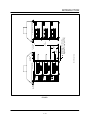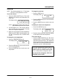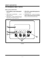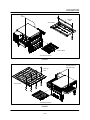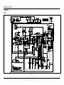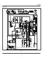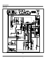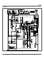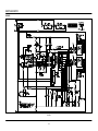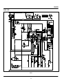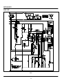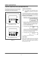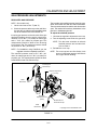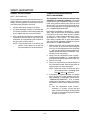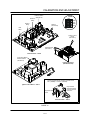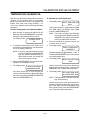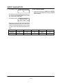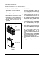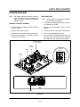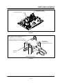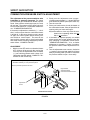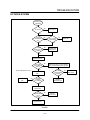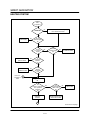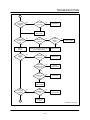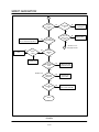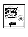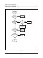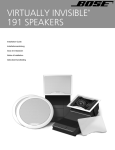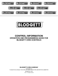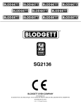
1
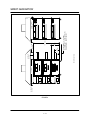
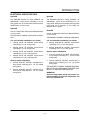
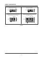
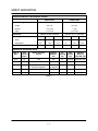
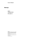
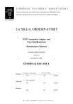
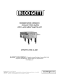
SMART GENERATION
CONVEYOR OVEN SERIES
SERVICE AND REPAIR MANUAL
BLODGETT OVEN COMPANY
www.blodgett.com
50 Lakeside Avenue, Box 586, Burlington, Vermont 05402 USA Telephone, (802) 658Ć6600 Fax: (802)864Ć0183
PN M10306 Rev C (11/01)
E 2001 - G.S. Blodgett Corporation
TABLE OF CONTENTS
This page intentionally left blank.
ii
TABLE OF CONTENTS
1. INTRODUCTION
Oven Specifications . . . . . . . . . . . . . . . . . . . . . . . . . . . . . . . . . . . . . . . . . . . . . . . . . . . . . . . . . . . . . . .
Ventilation Requirements . . . . . . . . . . . . . . . . . . . . . . . . . . . . . . . . . . . . . . . . . . . . . . . . . . . . . . .
Electrical Specifications . . . . . . . . . . . . . . . . . . . . . . . . . . . . . . . . . . . . . . . . . . . . . . . . . . . . . . . .
Gas Specifications . . . . . . . . . . . . . . . . . . . . . . . . . . . . . . . . . . . . . . . . . . . . . . . . . . . . . . . . . . . .
1-1
1-1
1-4
1-6
2. OPERATION
Standard Manual Control . . . . . . . . . . . . . . . . . . . . . . . . . . . . . . . . . . . . . . . . . . . . . . . . . . . . . . . . . .
Programmable Menu Control . . . . . . . . . . . . . . . . . . . . . . . . . . . . . . . . . . . . . . . . . . . . . . . . . . . . . .
Oven Adjustments for Cooking . . . . . . . . . . . . . . . . . . . . . . . . . . . . . . . . . . . . . . . . . . . . . . . . . . . . .
Schematics . . . . . . . . . . . . . . . . . . . . . . . . . . . . . . . . . . . . . . . . . . . . . . . . . . . . . . . . . . . . . . . . . . . . . .
SG2136G . . . . . . . . . . . . . . . . . . . . . . . . . . . . . . . . . . . . . . . . . . . . . . . . . . . . . . . . . . . . . . . . . . . .
SG2136E - 2 Wire . . . . . . . . . . . . . . . . . . . . . . . . . . . . . . . . . . . . . . . . . . . . . . . . . . . . . . . . . . . .
SG2136E - 3 Wire . . . . . . . . . . . . . . . . . . . . . . . . . . . . . . . . . . . . . . . . . . . . . . . . . . . . . . . . . . . .
SG2136E - 4 Wire . . . . . . . . . . . . . . . . . . . . . . . . . . . . . . . . . . . . . . . . . . . . . . . . . . . . . . . . . . . .
SG3240G . . . . . . . . . . . . . . . . . . . . . . . . . . . . . . . . . . . . . . . . . . . . . . . . . . . . . . . . . . . . . . . . . . . .
SG3240E - 3 Wire . . . . . . . . . . . . . . . . . . . . . . . . . . . . . . . . . . . . . . . . . . . . . . . . . . . . . . . . . . . .
SG3240E - 4 Wire . . . . . . . . . . . . . . . . . . . . . . . . . . . . . . . . . . . . . . . . . . . . . . . . . . . . . . . . . . . .
2-1
2-3
2-5
2-8
2-8
2-9
2-10
2-11
2-12
2-13
2-14
3. CALIBRATION AND ADJUSTMENT
Control Identification and Registration . . . . . . . . . . . . . . . . . . . . . . . . . . . . . . . . . . . . . . . . . . . . . . .
Gas Pressure Adjustments . . . . . . . . . . . . . . . . . . . . . . . . . . . . . . . . . . . . . . . . . . . . . . . . . . . . . . . . .
Convection Blowers . . . . . . . . . . . . . . . . . . . . . . . . . . . . . . . . . . . . . . . . . . . . . . . . . . . . . . . . . . . . . . .
Temperature Calibration . . . . . . . . . . . . . . . . . . . . . . . . . . . . . . . . . . . . . . . . . . . . . . . . . . . . . . . . . . .
Belt Speed Calibration . . . . . . . . . . . . . . . . . . . . . . . . . . . . . . . . . . . . . . . . . . . . . . . . . . . . . . . . . . . .
3-1
3-2
3-5
3-6
3-8
4. PARTS REPLACEMENT
PLC Replacement and Programming . . . . . . . . . . . . . . . . . . . . . . . . . . . . . . . . . . . . . . . . . . . . . . . .
Interface Board . . . . . . . . . . . . . . . . . . . . . . . . . . . . . . . . . . . . . . . . . . . . . . . . . . . . . . . . . . . . . . . . . . .
Circulating Fan Pressure Switch . . . . . . . . . . . . . . . . . . . . . . . . . . . . . . . . . . . . . . . . . . . . . . . . . . . .
Combustion Pressure Switch Adjustment . . . . . . . . . . . . . . . . . . . . . . . . . . . . . . . . . . . . . . . . . . . .
4-1
4-2
4-3
4-5
5. TROUBLESHOOTING
Fault Display Indicators . . . . . . . . . . . . . . . . . . . . . . . . . . . . . . . . . . . . . . . . . . . . . . . . . . . . . . . . . . . .
DC Drive System . . . . . . . . . . . . . . . . . . . . . . . . . . . . . . . . . . . . . . . . . . . . . . . . . . . . . . . . . . . . . . . . .
Heating System . . . . . . . . . . . . . . . . . . . . . . . . . . . . . . . . . . . . . . . . . . . . . . . . . . . . . . . . . . . . . . . . . .
Convection System . . . . . . . . . . . . . . . . . . . . . . . . . . . . . . . . . . . . . . . . . . . . . . . . . . . . . . . . . . . . . . .
Reference Tables . . . . . . . . . . . . . . . . . . . . . . . . . . . . . . . . . . . . . . . . . . . . . . . . . . . . . . . . . . . . . . . . .
Heating Element Resistance . . . . . . . . . . . . . . . . . . . . . . . . . . . . . . . . . . . . . . . . . . . . . . . . . . . .
Probe Resistance vs Temperature . . . . . . . . . . . . . . . . . . . . . . . . . . . . . . . . . . . . . . . . . . . . . . .
5-1
5-2
5-3
5-7
5-8
5-8
5-8
i
TABLE OF CONTENTS
This page intentionally left blank.
ii
CHAPTER 1
INTRODUCTION
SMART GENERATION
OVEN SPECIFICATIONS
VENTILATION REQUIREMENTS
inĆline tempering unit. Air supplied directly from outĆ
side the building to the kitchen or oven area, nonĆ
tempered, can be used as supply air but the design
must accommodate potential operational and enviĆ
ronmental drawbacks.
A mechanically driven ventilation system is reĆ
quired for the removal of excess heat and cooking
vapors. For gas models, a ventilation system is
also required for the removal of the products of gas
combustion. The necessity for a properly designed
and installed ventilation system cannot be over
emphasized.
NOTE: In NO case should supply air blow at or
near the cooking chamber openings as
that would adversely affect the cooking
consistency and the reliability of the oven.
The following are general recommendations and
guidelines for good ventilation. Your specific apĆ
plication may require the services of a ventilation
engineer or consultant
The hood should be sized to completely cover the
equipment plus an overhang of at least 6" (15cm)
on all sides not adjacent to a wall. The distance
from the floor to the lower edge of the hood should
not exceed 7' (2.1m). See FIGURE 2.
The ventilation hood must work well with the building
heating, ventilation and air conditioning (HVAC) sysĆ
tem. The hood exhaust and the supply air flows
should be sized appropriately. Supply air must be
provided by either the hood system or the building
HVAC system in order to prevent a negative presĆ
sure in the oven area. Supply air should replace
approximately 80% of the air flow exhausted by the
hood. The table below can be used as a guideline,
but the correct air flow values depend on the effiĆ
ciency of the hood design, the amount of air flow
around the oven, and the current air flow in and out
of the kitchen or oven area (for existing facilities).
MODEL
SINGLE
DOUBLE
U.S. and Canadian installations
Refer to your local ventilation codes. Requirements
may vary by city, county, province or state. In the
absence of local codes, refer to the National venĆ
tilation code titled, Standard for the Installation of
Equipment for the Removal of Smoke and Grease
Laden Vapors from Commercial Cooking EquipĆ
ment", NFPAĆ96ĆLatest Edition.
General export installations
Installation must conform with Local and National
installation standards. Local installation codes
and/or requirements may vary. If you have any
questions regarding the proper installation and/or
operation of your Blodgett oven, please contact
your local distributor. If you do not have a local disĆ
tributor, please call the Blodgett Oven Company at
0011Ć802Ć860Ć3700.
TRIPLE
Exhaust Volume - CFM (M3/min)
SG2136
400Ć500
(14Ć17)
800Ć1000
(23Ć28)
1200Ć150
0 (34Ć43)
SG3240
800Ć1000
(23Ć28)
1200Ć1600
(34Ć46)
2000Ć240
0 (57Ć68)
Supply Requirements - CFM (M3/min)
SG2136
320Ć400
(12Ć14)
640Ć800
(18Ć23)
960Ć1200
(27Ć34)
SG3240
640Ć800
(18Ć23)
960Ć1280
(27Ć36)
1600Ć192
0 (46Ć54)
WARNING:
Failure to properly vent the oven can be hazardĆ
ous to the health of the operator and may result
in operational problems, unsatisfactory baking
and possible damage to the equipment.
Damage sustained as a direct result of improper
ventilation will not be covered by the ManufacturĆ
er's warranty.
TABLE 1
Ideally, supply air is provided through the building
HVAC system or, secondly, through the hood with an
1-1
6" (15.2 cm)
Minimum
FIGURE 1
1-2
9"
(22.7 cm)
20"
(50.8 cm)
60"
(152.4 cm)
6" (15 .2cm)
Minimum
Triple Stack - 6.5" (17 cm)
Double Stack - 17.5" (44.5 cm)
Single Stack - 23.5" (59.7 cm)
SG2136 Series Shown
64" (162.5 cm)
3" (7.6 cm)
Minimum
0" (0cm) if wall or 6" (15.2 cm)
INTRODUCTION
6" (15.2 cm)
Minimum
77" (196 cm)
SG3240 Series Shown
3" (7.6 cm)
Minimum
FIGURE 2
1-3
Triple Stack - 7" (17.8 cm)
Double Stack - 17.25" (43.8 cm)
Single Stack - 23.25" (59 cm)
14"
(35.5 cm)
24"
(61 cm)
72" (182 cm)
6" (15 .2cm)
Minimum
0" (0cm) if wall or
6" (15.2 cm)
SMART GENERATION
INTRODUCTION
ELECTRICAL SPECIFICATIONS
SG2136G
SG3240G
The SG2136G requires a 5 Amp, 50/60HZ, 1,
208Ć240VAC, 3 wire service consisting of L1, L2
and ground. Use 75_C rated cable. Size wire to NaĆ
tional Electric or local codes.
The SG3240G requires a 5 Amp, 50/60HZ, 1,
208Ć240VAC, 3 wire service consisting of L1, L2
and ground. Wiring from the power source to these
units must be a minimum of #16 AWG CU.
stranded wire or larger.
SG2136E
SG3240E
Use 75_C rated cable. Size wire to National Electric
or local codes.
Use 90_C rated cable. Size wire to National Electric
or local codes.
The SG2136E is available in 6 electrical configuraĆ
tions.
The SG3240E is available in 4 electrical configurations.
U.S. and Canadian installations (or similar)
U.S. and Canadian installations (or similar)
D
76 amp, 60 HZ, 1, 208 VAC, 2 wire service
consisting of L1, L2, and ground.
D
69 amp, 50/60 HZ, 3, 208 VAC, 4 wire service
consisting of L1, L2, L3, and ground.
D
66 amp, 60 HZ, 1, 240 VAC, 2 wire service
consisting of L1, L2, and ground.
D
80 amp, 50/60 HZ, 3, 240 VAC, 4 wire service
consisting of L1, L2, L3, and ground.
D
44 amp, 60 HZ, 3, 208 VAC, 3 wire service
consisting of L1, L2, L3 and ground.
General export installations
D
38 amp, 60 HZ, 3, 240 VAC, 3 wire service
consisting of L1, L2, L3 and ground.
General export installations
D
D
24 amp, 50/60 HZ, 3 WYE, 220/380 VAC, 4
wire service consisting of L1, L2, L3, neutral
and ground.
D
41.5 amp, 50/60 HZ, 3 WYE, 230/400 VAC,
4 wire service consisting of L1, L2, L3, neutral
and ground.
D
40 amp, 50/60 HZ, 3 WYE, 240/415 VAC, 4
wire service consisting of L1, L2, L3, neutral
and ground.
THE BLODGETT CANNOT ASSUME RESPONSIĆ
BILITY FOR LOSS OR DAMAGE SUFFERED AS A
RESULT OF IMPROPER INSTALLATION.
23 amp, 50/60 HZ, 3 WYE, 240/415 VAC, 4
wire service consisting of L1, L2, L3, neutral
and ground.
WARNING!!
Incorrect single phase wiring may result in exĆ
tensive damage to electrical components and
fire in the electrical box.
1-4
SMART GENERATION
SG2136E Single Phase Power
SG2136G and SG3240G
L1
Supply
L2
L1
208Ć240
Oven
Supply
Supply
L2
L3
208Ć240
Oven
SG2136E and SG3240E Wye Three Phase Power
General Export Installations
SG2136E and SG3240E Delta Three Phase Power
U.S. and Canadian Installations (or similar)
L1
L2
208 or 240
(typical)
400/
415
L1
Oven
Supply
L2
400/415
L3
400/415
N
FIGURE 3
1-5
230/
240
Oven
INTRODUCTION
GAS SPECIFICATIONS
GAS CONNECTIONS
NOTE: For natural gas meter sizing, consult your
local gas company to ensure that your meĆ
ter will provide the proper supply.
Domestic and General Export installations
The gas line should be large enough to accommoĆ
date the peak demand of all the gas appliances.
TABLE 2 reflects a straight line, 50 foot run with no
coupling restrictions and no other appliances
drawing service. Gas line installations MUST conĆ
form to National Fuel Gas Code NFPA 54/ANSI
Z223.1 Sec. 1.4 (Latest Edition). TABLE 2 should
be used as a guideline only.
Installations within the U.S.
1. Add the total BTU's/hr of all the gas appliances.
2. Convert BTU's to cubic ft/hr using the formula
Cu Ft/Hr = 1000 BTU/Hr for natural gas.
3. Size the meter accordingly.
Installations outside the U.S.
NOTE: For any pipe runs over 50 feet (15 m), conĆ
sult the factory.
1. Add the total M3/min of all the appliances.
2. Size the meter accordingly.
GAS REQUIREMENTS
The firing rate for the SG3240G is 110,000 BTU/hr
(32.2 kW/hr) (116 MJ/hr). The firing rate for the
SG2136G is 60,000 BTU/hr (17.6KW) (63 MJ/hr).
SG2136G DOMESTIC AND GENERAL EXPORT
Natural Gas
Propane Gas
Single
3/4" line
3/4" line
Double
3/4" line
3/4" line
Triple
1" line
3/4" line
Orifice Size
3.45mm (0.136") diameter
2.08mm (0.082") diameter
Gas Line Sizing
Incoming Gas Pressure
W.C.
kPa
mbar
W.C.
kPa
mbar
7"
1.74
17.4
12.5"
3.11
31.1
5.5"
1.36
13.7
11"
2.73
27.4
3.5"
0.87
8.7
10"
2.50
25.0
Static
Operational
Manifold Burner Pressure
SG2136G CE APPROVED UNITS
Type of
Gas
Inlet
Pressure
mbars
Burner Pressure
mbars
Injector
Diameter
mm
Air
Opening
mm
Pilot
Injector
mm
Standard
Delivery
Value kW (HS)
G25
25
13
3,45
5,1
2 x 0,63
17,6 Nat. Gas
G20
20
8.7
3,45
5,1
2 x 0,63
17,6 Nat. Gas
G20/G25
20/25
Totally Inscrewed
Pressure Regulator
3,45 plus
preĆinjector
5,1
2 x 0,63
17,6 Nat. Gas
G30
30/50
20
2,08
5,1
2 x 0,30
17,6 Butane
G31
30/37/50
25
2,08
5,1
2 x 0,30
17,6 Propane
TABLE 2
1-6
SMART GENERATION
SG3240G DOMESTIC AND GENERAL EXPORT
Natural Gas
Propane Gas
Single
3/4" line
3/4" line
Double
1Ć1/4" line
1" line
Triple
1Ć1/4" line
1Ć1/4" line
Orifice Size
4.80mm (0.189") diameter
2.82mm (0.111") diameter
Gas Line Sizing
Incoming Gas Pressure
W.C.
kPa
mbar
W.C.
kPa
mbar
7"
1.74
17.4
12.5"
3.11
31.1
5.5"
1.36
13.7
11"
2.73
27.4
3.5"
0.87
8.7
10"
2.50
25.0
Static
Operational
Manifold Burner Pressure
SG3240G CE APPROVED UNITS
Type of
Gas
Inlet
Pressure
mbars
Burner Pressure
mbars
Injector
Diameter
mm
Air
Opening
mm
Pilot
Injector
mm
Standard
Delivery
Value kW (HS)
G25
25
13.5
4,8
10
2 x 0,63
32,2 Nat. Gas
G20
20
8.7
4,8
10
2 x 0,63
32,2 Nat. Gas
G20/G25
20/25
Totally Inscrewed
Pressure Regulator
4,8 plus
preĆinjector
10
2 x 0,63
32,2 Nat. Gas
G30
30/50
20
2,8
10
2 x 0,30
32,2 Butane
G31
30/37/50
25
2,8
10
2 x 0,30
32,2 Propane
TABLE 3
1-7
INTRODUCTION
This page intentionally left blank.
1-8
CHAPTER 2
OPERATION
SMART GENERATION
STANDARD MANUAL CONTROL
MANUAL CONTROL DESCRIPTION
1. DIGITAL DISPLAY - two line display gives the
time, temperature and other control related inĆ
formation.
4. ARROW KEYS - press to change the set time
and temperature in the display.
5. TIME KEY - press to change the cook time.
2. OVEN ON/OFF (ON/STANDBY) - controls
power to the oven.
6. ENTER/RESET KEY - press to save new cook
time or temperature. Also press to silence the
alarm in case of a fault. The alarm will sound
every ten seconds until the fault clears.
3. TEMPERATURE KEY - press to change the
cook temperature.
1
2
6
3
4
FIGURE 1
2-1
5
OPERATION
OPERATION
To change the cook time:
NOTE: The following example is in _F. The display
will read _C if programmed in celsius.
1. Press the TIME key (5).
To turn the oven on:
The display reads:
1. Press the OVEN ON/OFF key (2). The control
defaults to the last time and temperature setĆ
tings used.
The display reads:
2. Press the ARROW keys (4) to scroll to the deĆ
sired cook time.
SET TEMP XXXF HEAT
COOK TIME XX:XX
3. Press the ENTER key (6) to set the new cook
time.
NOTE: HEAT appears in the top line of the disĆ
play whenever the control calls for heat.
To display the actual oven temperature:
1. Press both ARROW keys (4) .
2. The fans begin to run. The conveyor belt beĆ
gins to travel at the set cook time. The heat
rises to the setpoint temperature.
The display reads:
3. When the oven reaches the set temperature,
READY and SET TEMP flash alternately in the
top line of the display and an audible alarm
sounds.
TEMP XXXF
DOWN - EXIT
2. Press the down arrow key to return the display
to the setpoint time and temperature.
To turn the oven off:
To change the cook temperature:
1. Press the OVEN ON/OFF key (2). The oven is
equipped with a coolĆdown feature for motor
shaft and bearing protection. This enables the
blower motor(s) to run regardless of the conĆ
troller status. The blower(s) continue to run unĆ
til the oven cools to a safe temperature.
1. Press the TEMPERATURE key (3).
The display reads:
SET COOK TIME
XX:XX
SET POINT TEMP
XXXF
2. Press the ARROW keys (4) to scroll to the deĆ
sired cook temperature.
This oven, supplied with remote control, is
equipped with an emergency shut down
switch. Should you need to stop the belt,
fans, or heat press the emergency switch.
3. Press the ENTER key (6) to set the new cook
temperature.
Do not use the emergency switch as a
GENERAL on/off switch!
2-2
SMART GENERATION
PROGRAMMABLE MENU CONTROL
MENU CONTROL DESCRIPTION
1. DIGITAL DISPLAY - two line display gives the
time, temperature and other control related inĆ
formation.
4. MENU KEYS - programmable product keys.
Up to four different time and temperature setĆ
tings can be saved.
2. OVEN ON/OFF (ON/STANDBY) - controls
power to the oven.
5. ENTER/RESET KEY - press to save settings
while programming. Also press to silence the
alarm in case of a fault. The alarm will sound
every ten seconds until the fault clears.
3. ARROW KEYS - press to change the time and
temperature in the display. Also press to scroll
through menus during programming.
1
2
3
5
4
FIGURE 2
2-3
OPERATION
MENU PROGRAMMING
OPERATION
NOTE: The following example is in _F. The display
will read _C if programmed in celsius.
1. Press the OVEN ON/OFF key (2). The control
defaults to the last time and temperature setĆ
tings used.
To enter programming mode:
1. With the oven off, press and hold the UP ARĆ
ROW key (3) and the ENTER/RESET key (5) siĆ
multaneously for approximately three seconds.
The display reads:
The display reads:
ACCESS CODE
000
NOTE: HEAT appears in the top line of the disĆ
play whenever the control calls for heat.
2. Press and hold the UP ARROW key (3) until the
bottom line of the display reads 111 (the store
access code).
2. Press the desired MENU key (4).
3. The fans begin to run. The conveyor belt beĆ
gins to travel at the set cook time. The heat
rises to the setpoint temperature.
3. Press the ENTER/RESET key (5) to enter the
programming mode.
4. When the oven reaches the set temperature,
READY and SET are displayed. The heat rises
to the setpoint temperature. TEMP flash alterĆ
nately in the top line of the display and an audiĆ
ble alarm sounds.
To program the menu keys:
1. The display reads:
SELECT MENU KEY
MENU 1, 2, 3, OR 4
NOTE: To change the cook time and temperaĆ
ture press any of the other menu keys.
2. Press the MENU key (4) to be programmed.
NOTE: For this example we will program menu
key 1.
3. The display reads:
To display the actual oven temperature:
1. Press both ARROW keys (4) .
MENUĆ1 SELECT TEMP
XXXF PRESS ENTER
The display reads:
Use the ARROW keys (3) to scroll to the deĆ
sired cook temperature. Press the ENTER key
(5) to store the new cook temperature.
4. The display reads:
XXXF
DOWN - EXIT
2. Press the down arrow key to return the display
to the setpoint time and temperature.
To turn the oven off:
MENUĆ1 COOK TIME
XX:XX PRESS ENTER
1. Press the OVEN ON/OFF key (2). The oven is
equipped with a coolĆdown feature for motor
shaft and bearing protection. This enables the
blower motor(s) to run regardless of the conĆ
troller status. The blower(s) continue to run unĆ
til the oven cools to a safe temperature.
Use the ARROW keys (3) to scroll to the deĆ
sired cook time. Press the ENTER key (5) to
store the new cook time.
5. The display flashes:
MĆX TEMP XXXF HEAT
COOK TIME XX:XX
MENUĆ1
PROGRAM DONE
This oven, supplied with remote control, is
equipped with an emergency shut down
switch. Should you need to stop the belt,
fans, or heat press the emergency switch.
To exit the programming mode:
1. Press and hold the UP ARROW key (3) and the
ENTER/RESET key (5) simultaneously for
approximately three seconds.
Do not use the emergency switch as a
GENERAL on/off switch!
NOTE: If no key is pressed for 60 seconds, the
control automatically exits the program
mode.
2-4
SMART GENERATION
OVEN ADJUSTMENTS FOR COOKING
The combination of belt time, oven temperature,
and air flow are important for achieving quality reĆ
sults from your Blodgett conveyor oven. Use the
following guidelines to adjust the belt time and
oven temperature of your unit. For questions reĆ
garding further oven adjustments, please contact
your local Blodgett Sales Representative for assisĆ
tance.
Air flow adjustments may be necessary to fine tune
the oven for your particular product. The air plate,
located at the top of the baking chamber, contains
holes that can be covered using BlockĆoff Plates.
The plates can easily be adjusted to regulate the
air flow for your particular needs. Use the following
guidelines to adjust the BlockĆoff Plates. See
FIGURE 4.
CONVEYOR SPEED AND OVEN TEMPERATURE
1. Ensure the oven is Off and completely cooled.
2. Open the front access door.
Conveyor belt speed (cook time) and oven temperĆ
ature are the two variables used when fine tuning
your oven for a specific product. To determine the
optimum bake time and temperature, make small
changes for each trial and keep one variable
constant. For example, if the oven temperature is
460_F (238_C) and the belt speed is 7 minutes, but
the pizza is not browned enough, increase the temĆ
perature to 475_F (246_C) and keep the belt speed
the same. However, if the center of the pizza is not
completely cooked, keep the oven temperature
the same, and increase the bake time to 7 minutes
and 30 seconds. In general, raise the bake temperĆ
ature to increase browning, and lengthen the belt
time to increase doneness.
3. Using the supplied air plate hook, pull the air
plate out of the oven.
4. Remove the wing nuts, screws, and washers
holding the BlockĆoff Plates.
5. Adjust the plates.
6. Replace the wing nuts, screws, and washers
to tightly secure the BlockĆoff plates in their
new locations. Make a sketch of the final airĆ
plate setup for future reference.
NOTE: One or two blockĆoff plates may be left
off entirely if appropriate to obtain the
desired results.
7. Replace the air plate.
FINISHED PRODUCT TEMPERATURES
8. Close the front access door.
Internal temperatures of the cooked products
should be measured immediately after the product
exits the cooking chamber to ensure a safe food
temperature. Internal pizza temperatures should be
over 165_F (74_C). Minimum temperature guideĆ
lines vary depending on the food items.
The following examples illustrate air flow regulation.
NOTE: The first half of the oven chamber greatly afĆ
fects the initial baking of the product, while
the last half largely affects the browning.
D
A good bake time and temperature have been
established, but more top browning is desired.
Slide one of the BlockĆoff Plates to uncover a
row of holes toward the exit end of the oven.
D
The bottom of the pizza is golden brown, but
the top is too dark. Close rows at the exit end
of the oven to reduce final browning.
D
The center of the pizza is still doughy and the
toppings are not fully cooked. Open up rows at
the chamber entrance and close rows at the
chamber exit.
AIR FLOW ADJUSTMENTS
Slide the product clearance adjustment plates to
the lowest possible setting for your menu items.
Lowering the clearance plates will reduce the
amount of hot air escaping from the chamber
openings.
2-5
OPERATION
Air
Slides
BlockĆOff
Plate
Air Flow Plate
Air Flow Plates
SG2136 Series Shown
FIGURE 3
Product Clearance
Adjustment Plate
BlockĆOff
Plate
Air Flow Plate
SG3240 Series Shown
FIGURE 4
2-6
SMART GENERATION
SCHEMATICS
SG2136G
FIGURE 5
2-7
OPERATION
SG2136E - 2 WIRE
FIGURE 6
2-8
SMART GENERATION
SG2136E - 3 WIRE
FIGURE 7
2-9
OPERATION
SG2136E - 4 WIRE
FIGURE 8
2-10
SMART GENERATION
SG3240G
FIGURE 9
2-11
OPERATION
SG3240E - 3 WIRE
FIGURE 10
2-12
SMART GENERATION
SG3240E - 4 WIRE
FIGURE 11
2-13
CHAPTER 3
CALIBRATION AND
ADJUSTMENT
SMART GENERATION
CONTROL IDENTIFICATION AND REGISTRATION
CONTROL REGISTRATION
The following instructions are for both the standard
manual and programmable menu PLC controls.
See FIGURE 12 for control identification.
NOTE: The following control registration proceĆ
dure applies to installations in North AmeriĆ
ca only.
The installer may be required to obtain a registration
number from the Blodgett Oven Service Department
before the unit can be operated. Use the following
procedure for control registration:
1. Registration is required if after applying power
to the oven for the first time the display reads:
CALL SRVC FOR REG #
1Ć800Ć331Ć5842
2. Note the serial number of the oven and call
Blodgett Oven Service at the number shown on
the display to obtain your registration number.
Standard Manual PLC Control
3. Press the ENTER/RESET key.
4. The display reads:
REG #
XXXX
Use the arrow keys to scroll to the registration
number for your unit. Press the ENTER/RESET
key to enter the registration number.
5. The display reads:
OVEN OFF
6. The oven can now be turned on.
VENTILATION
Menu Programmable PLC Control
Ignite a smoke candle inside the oven cavity. Note
the amount of smoke removed by the ventilation
system. The recommended amount of smoke to
be removed is 90-100%.
FIGURE 12
3-1
CALIBRATION AND ADJUSTMENT
GAS PRESSURE ADJUSTMENTS
REGULATED GAS PRESSURE
NOTE: Gas models only.
The incoming and manifold pressure should be meaĆ
sured at the same time with two water manometers.
The oven must be turned on and the main burner valve
open. This method will reveal any obstructions in the
pipe line or inadequate pipe size.
1. Let the oven heat to 510_F (266_C).
2. Check the pressure at the tap on the multiĆfuncĆ
tion gas valve or at the tap on the tee fitting at the
rear of the electrical box. See FIGURE 13.
To adjust the manifold pressure
Incoming gas pressure to the unit, with all the gas
appliances drawing from the supply, should be a
minimum of 5.5" W.C. (13.7 mbar) for natural gas
and 11" W.C. (27.4 mbar) for propane gas. This
measurement should be taken at the Incoming
Line Pressure Tap. The maximum pressure should
not exceed 13" W.C. (32.3 mbar).
1. Unscrew the regulator adjustment cover cap.
2. Turn the adjusting screw inside the gas valve.
NOTE: Turn the screw clockwise to raise the
manifold pressure and counterĆclockĆ
wise to lower it.
3. Reinstall the cover cap.
NOTE: For installations using GĆ20/GĆ25 gas, the
regulator must be completely screwed in.
NOTE: The cover cap acts as a flow limiter, in the
event of a diaphragm rupture it will limit the
flow of gas into the building.
The manifold pressure must be 3.5" W.C. (8.7
mbar) for natural gas and 10" W.C. (25 mbar) for
propane gas. This measurement should be taken
at the Manifold and Pilot Pressure Tap.
Incoming Line
Pressure Tap*
Regulator Adjustment
Cover Cap
Water
Manometer
Regulator
Adjustment Screw
(inside)
Manifold and
Pilot Pressure Tap*
Water
Manometer
* Pipe plug used in US/Canadian ovens
FIGURE 13
3-2
SMART GENERATION
PRIMARY AIR ADJUSTMENT
COMBUSTION BLOWER PRESSURE
SWITCH ADJUSTMENT
NOTE: Gas models only.
The adjustment of the pressure switches after
installation is extremely important. The switch
proves that the gas combustion air blower is operaĆ
tional. If the pressure switch stays open, the oven
will not heat. The operator will be given both audiĆ
ble and visual alarms for a combustion blower failĆ
ure: COMBUSTION BLWR FAIL"
The air shutter disc on the burner blower motor, loĆ
cated inside the control box at the top of the asĆ
sembly, is factory adjusted to provide the most effiĆ
cient blue flame possible at sea level.
1. Visually examine the quality of the flame.
2. If it needs adjusting, increase or decrease the
air mixture to attain the best flame quality. Be
sure to tighten the lock nut when finished.
If the switch is adjusted too sensitively (- clockĆ
wise), it will not open when the combustion blower
is turned off. In this case, when the oven is turned
on again, the control system would see the presĆ
sure switch as stuck closed." The oven will not
heat, and the operator will be given both audible
and visual alarms indicating combustion pressure
switch failure: COMB PS FAILURE."
3. If the combustion blower alarm is actuated, the
combustion pressure switch may need to be
readjusted. The adjustment screw is visible on
the top of the pressure switch.
NOTE: The pressure switch is located on the
ignition control board on the pull out
tray at the bottom of the electrical box.
1. With the oven OFF and the combustion blower
OFF (it'll shut off 20 seconds after turning the
oven off), turn the adjustment screw clockwise
(-) just until the pressure switch closes (indiĆ
cated when the LED marked COMB PS" is illuĆ
minated on the control tray).
2. Slowly turn the adjustment screw counterclockwise approximately (+) 1/4 turn PAST the
point where the switch opens (LED shuts off).
3. Turn the oven ON.
4. Place your hand over the circular air shutter on
the combustion blower. Close off part of the air
opening with your hand and fingers.
NOTE: Adjust the switch to close only when
the combustion fan is operating either
with very little or no restriction
5. If the switch is adjusted properly, an audible
alarm sounds and a fault appears in the disĆ
play indicating a combustion blower failure:
COMBUSTION BLWR FAIL." If so, no further
adjustment is necessary. If there is no alarm,
the pressure switch needs adjustment as folĆ
lows:
A.) Turn the adjustment screw counterclockwise (+) another 1/4 turn and test
again if it will close easily by blocking it with
your hand. This allows the pressure switch
to open more easily.
3-3
CALIBRATION AND ADJUSTMENT
Circulation Blowers'
Pressure Switch
(See View D)
Blower 2
Relay
View B
SW4
Blower 1
Relay
ENB 2
DIR 2
ENB 1
DIR 1
Switch 4
(See View B)
Heat
Relay
Ignition Control
Board
(See View C)
Interface Board
(See View A)
Interface Board - View A
Combustion Blower
Pressure Switch
(See View D)
Interface Slide Tray
(SG3240G shown)
Typical circulation blower pressure expected is .30"
W.C. (SG3240) or .25" W.C. (SG2136)
Ignition Control Board - View C
Adjustment
Screw
+ -
High Side Port
(Internal Snubber)
Connect Pressure
Hose here
Pressure Switch - View D
FIGURE 14
3-4
SMART GENERATION
CONVECTION BLOWERS
MOTOR ROTATION OF CONVECTION BLOWERS
CHECKING THE LOW LIMIT OF THE BLOWERS:
The correct amp draw for most gas conveyor
ovens is 1 amp when the oven is hot.
1. Turn the oven on. Let it heat to 200_F (93_C).
Shut the oven off. The blowers should come
back on in several seconds.
If the amp draw is less than .5, remove the back of
the oven and check for proper motor rotation direcĆ
tion. See FIGURE 15.
NOTE: Open the small front access door to
speed cooling.
Due to its vertical positioning the motor direction is
reference from the end of the motor (EOM) as
viewed from the rear of the oven.
NOTE: To view actual temperature, press the
arrow keys simultaneously. To return to
normal display operation, press the
down arrow key.
2. When the blowers shut off, turn the oven on.
Press both arrow keys to display the actual
temperature and verify that the blowers shut
off between 135_F and 170_F (57Ć77_C).
Blower
Motor
Motor #1
(Side view)
(Top view)
FIGURE 15
3-5
Motor #2
Control Box
SG3240
BLOWER WHEEL ROTATION
Slinger
Cooling Fan
CALIBRATION AND ADJUSTMENT
TEMPERATURE CALIBRATION
To Calibrate the Cook Temperature:
After the oven has been cycling at the normal temĆ
perature for 60 minutes, place a temperature
probe in the center of the oven to verify proper caliĆ
bration. If the oven is not cycling to within 5_F
(3_C) of the setpoint use the following calibration
procedure.
1. The display reads:
Use the arrow keys to toggle between TEMP
and TIME. When the display reads TEMP,
press the ENTER/RESET key.
To Enter Configuration and Calibration Mode:
1. With the oven off, press and hold the UP ARĆ
ROW key and the ENTER/RESET key simultaĆ
neously for approximately three seconds.
The display reads:
NOTE: The control will stay in the calibration
mode until the UP ARROW and the ENĆ
TER/RESET keys are pressed simultaĆ
neously for about three seconds.
ACCESS CODE
000
2. The oven continues to operate; however, the
conveyor does not move.
2. To enter the service level access menu, press
and hold the UP ARROW key until the bottom
line of the display reads 331.
3. The display reads:
NOTE: If no key is pressed within 60 seconds
or if the UP ARROW and ENTER/RESET
keys are pressed simultaneously for
about three seconds, the display will
return to the previous mode.
SELECT TEMP MODE
DEGREES X
Use the arrow keys to toggle between_ F and_ C.
Press the ENTER/RESET key to select the deĆ
sired temperature units.
4. The display reads:
3. Press the ENTER/RESET key to enter the ConĆ
figuration and Calibration mode.
4. The display reads:
SELECT TEMP/TIME CAL
XXXX
SELECT CAL SET POINT
XXXF
Use the arrow keys to scroll to the desired calĆ
ibration set point temperature. Press the ENĆ
TER/RESET key to select that temperature.
SELECT PROGRAM
MAN/MENU MODE
5. The display reads:
Use either arrow key to scroll through the
choices on the bottom line of the display. When
the bottom line reads CALIBRATION ROUTINE
press the ENTER/RESET key.
SET POINT TEMP XXXF
CAL PROBE TEMP XXXF
NOTE: The temperature in line two of the disĆ
play will be flashing.
Use the arrow keys to scroll to the actual temĆ
perature measured by the probe. Use the averĆ
age of the high and low temperatures seen
during heat cycling. Press the ENTER/RESET
key to enter the probe temperature.
3-6
SMART GENERATION
6. The display reads:
To Exit Configuration and Calibration Mode:
OVEN TEMP XXXF
OFFSET +(-)XXXF
1. Press and hold the UP ARROW and ENTER/
RESET keys simultaneously for approximately
three seconds.
NOTE: The offset equals the setpoint minus
the probe temperature.
NOTE: The top line now displays the operating
oven temperature including the offset.
You can use the arrow keys to fine tune the offĆ
set by scrolling to a desired offset value. Press
the ENTER/RESET key to accept the offset.
7. The display reads:
CALIBRATION DONE?
UP-EXIT DOWN-CONT
Press the up arrow key to exit the Temperature
Calibration mode and return to the service levĆ
el menu or press the down arrow key to return
to step 3 of the temperature calibration proceĆ
dure.
3-7
CALIBRATION AND ADJUSTMENT
BELT SPEED CALIBRATION
To Calibrate the Belt Speed:
Place an object on the belt. Time its passage from
entrance to exit. If the actual speed is not within 5 seconds of the set time, check the calibration setĆ
tings as follows.
1. The display reads:
NOTE: Measure using the leading or the trailing
edge. Do not use the leading edge in and
the trailing edge out.
Use the arrow keys to toggle between TEMP
and TIME. When the display reads TIME,
press the ENTER/RESET key.
To Enter Configuration and Calibration Mode:
NOTE: The control will stay in the calibration
mode until the UP ARROW and the ENĆ
TER/RESET keys are pressed simultaĆ
neously for about three seconds.
1. With the oven off, press and hold the UP ARĆ
ROW key and the ENTER/RESET key simultaĆ
neously for approximately three seconds.
The display reads:
SELECT TEMP/TIME CAL
XXXX
2. The display reads:
ACCESS CODE
000
SELECT OVEN LENGTH
XX
2. To enter the service level access menu, press
and hold the UP ARROW key until the bottom
line of the display reads 331.
Use the arrow keys to scroll to the proper oven
length. Press the ENTER/RESET key to select
the correct oven length.
NOTE: If no key is pressed within 60 seconds
or if the UP ARROW and ENTER/RESET
keys are pressed simultaneously for
about three seconds, the display will
return to the previous mode.
NOTE: Refer to the table on the next page for
correct calibration values.
3. The display reads:
3. Press the ENTER/RESET key to enter the ConĆ
figuration and Calibration mode.
4. The display reads:
SELECT SHAFT TEETH
XX
Use the arrow keys to scroll to the proper numĆ
ber of teeth on the conveyor shaft sprocket.
Press the ENTER/RESET key to select the corĆ
rect number of shaft teeth.
SELECT PROGRAM
MAN/MENU MODE
4. The display reads:
Use either arrow key to scroll through the
choices on the bottom line of the display. When
the bottom line reads CALIBRATION ROUTINE
press the ENTER/RESET key.
SELECT MOTOR TEETH
XX
Use the arrow keys to scroll to the proper numĆ
ber of teeth on the motor shaft sprocket.
Press the ENTER/RESET key to select the corĆ
rect number of motor teeth.
5. The display reads:
SELECT BELT RADIUS
X.XXXX
Use the arrow keys to scroll to the correct belt
radius. Press the ENTER/RESET key to select
the correct belt radius value.
3-8
SMART GENERATION
6. The display reads:
To Exit Calibration Mode:
SELECT MOTOR RATIO
XX
1. Press and hold the UP ARROW and ENTER/
RESET keys simultaneously for approximately
three seconds.
Use the arrow keys to scroll to the correct moĆ
tor ratio. Press the ENTER/RESET key to select
the correct motor ratio value.
7. The display reads:
TIME CAL DONE?
UP-EXIT DOWN-CONT
Press the up arrow key to exit the Belt Speed
Calibration Mode and return to the service levĆ
el menu, or press the down arrow key to return
to step 2 of the belt speed calibration proceĆ
dure.
Model
Oven Length
Shaft Teeth
Motor Teeth
Belt Radius
Motor Ratio
SG2136
36"
30
30
0.8850
18
SG3240
40"
15
15
0.8850
18
3-9
CHAPTER 4
PARTS REPLACEMENT
SMART GENERATION
PLC REPLACEMENT AND PROGRAMMING
PLC REMOVAL AND REPLACEMENT
PLC PROGRAMMING
1. Remove burner and control access cover.
1. With the oven off, press the UP ARROW key
and the ENTER/RESET keys simultaneously
for approximately 3 to 5 seconds. The display
will read ACCESS CODE.
2. Disconnect the ribbon cables.
3. Disconnect power supplies from both the PLC
and the RTD converter.
2. To enter the service access level, press and
hold the UP ARROW key until the bottom line
of the display reads 331.
4. Remove the probe wires from the RTD convertĆ
er.
5. Press down on the retaining latches that hold
the PLC and the RTD converter to the din rail.
3. After 331 appears in the display, press the ENĆ
TER/RESET key. The top line of the display
reads SELECT PROGRAM. The bottom line of
the display reads MAN/MENU.
6. Separate the PLC and RTD converter from
each other.
4. Press the ENTER/RESET key. Use the ARROW
keys to select either manual or menu mode.
Press the ENTER/RESET key to select your
choice.
7. Reverse steps 1-6 to install the new PLC.
Ribbon Cable plugs in here
5. Use the ARROW keys to scroll to the twin belt
choice. Press the ENTER/RESET key to enter
the menu. Use the ARROW keys to select your
choice.
Display
plugs in here
6. Press the ENTER/RESET key. Use the ARROW
keys to scroll to the gas or electric choice.
Press the ENTER/RESET key to enter the
menu. Use the ARROW keys to select your
choice.
Power Supply
plugs in here
7. Press the ENTER/RESET key. Use the ARROW
keys to scroll to the calibration mode. Press the
ENTER/RESET key to enter the menu.
Latch release
8. See page 3-8 Belt Speed Calibation instrucĆ
tions.
PLC
9. See page 3-6 for Temperature Calibration inĆ
structions.
RTDs plug in here
RTD Converter
FIGURE 1
4-1
PARTS REPLACEMENT
INTERFACE BOARD
NOTE: The interface board is sensitive to electroĆ
static discharge. Proper grounding preĆ
cautions are required before handling the
interface board.
BELT DIRECTION
NOTE: If motor direction is changed the belt direcĆ
tion must also be changed.
REMOVAL AND REPLACEMENT
1. Locate the enable/disable switches and direcĆ
tion switches on the IFB.
1. Remove the ribbon clable and other harnesses
from the board.
2. Toggle the enable/disable switch to the off
position.
2. Remove the pressure switch.
3. Choose the direction you wish the belt to travel.
3. Remove the old board from the control panel.
4. Turn on the enable/disable switch.
4. Install the new board by reversing the above
mentioned procedures.
5. The motor should be going in the direction you
want the belt to travel. If the motor is going in
the wrong direction, repeat this procedure.
Circulation Blowers'
Pressure Switch
Blower 2
Relay
View A
Blower 1
Relay
Switch 4
(See View A)
Heat
Relay
SW4
ENB 2
DIR 2
ENB 1
DIR 1
K1 LED
FIGURE 2
4-2
SMART GENERATION
CIRCULATING FAN PRESSURE SWITCH
REPLACEMENT
NOTE: If a Blower Failure alarm occurs during
heating, turn the adjustment screw on
the circulation pressure switch clockĆ
wise (-) about 1/4 turn; the switch
should stay closed at a higher temperĆ
ature now. Turn the oven OFF (into
Standby) and then ON to continue
heating.
1. If the oven contains pressure switch M9422
(see FIGURE 3), remove and discard.
2. Carefully remove and discard the jumper wires
from the pressure switch lead wires.
NOTE: If the lead wires are damaged,the interĆ
face board will need replacement.
3. Install the new pressure switch. See FIGURE 4
and FIGURE 5.
NOTE: The oven has a cool down feature that
causes the circulation blowers to conĆ
tinue to operate until an oven temperaĆ
ture between 130°F (54°C) and 170°F
(77°C) is reached. Turning the oven off
and then on again will cause all blowĆ
ers to shut off for approximately 5 secĆ
onds to verify pressure switch funcĆ
tion.
Pressure Switch
M9422
2. When the oven reaches the set point, turn the
oven OFF and then ON again to shut off the
blowers momentarily.
3. While the oven is off for the 5Ćsecond period,
REMOVE one of the circulation blower relays.
Do not remove the relay when the blowers
are in operation or failure to the Interface
Board may result.
4. After 5 seconds, the blowers start. If the switch
is adjusted properly an audible alarm sounds,
and a message appears in the display indicatĆ
ing a Blower Failure. If no alarm occurs, skip to
step 5. If the alarm actuates, no further adjustĆ
ment is necessary. Turn the oven OFF and
back ON again to get the 5Ćsecond off period,
and REINSTALL the circulation blower relay
during the off period.
5. If there is no alarm, the pressure switch needs
adjustment. Turn the adjustment screw counterĆ
clockwise (+) slowly until the switch opens and
the alarm actuates. Turn the oven OFF and back
ON again and REINSTALL the circulation blower
relay while the oven is in the off period. Let the
oven heat up to 550°F (288°C) again (step 1
above) and make sure the pressure switch stays
closed. GO TO STEP 2.
FIGURE 3
ADJUSTMENT
The adjustment of the circulation air pressure
switch after installation is extremely important.
The switch proves that the hot air circulation blowers
are operational. If the pressure switch is open, the
oven will not heat. If it is adjusted properly, it will also
detect if either blower has stopped for any reason.
The operator will be given both audible and visual
alarms for a blower failure: CIRC BLOWER FAIL."
If the switches are adjusted too sensitively (-"
clockwise), they might not open when the circulatĆ
ing fans are turned off. In this case, when the oven
is started again, the control system would see the
pressure switch as stuck closed." The oven will
not heat, and the operator will be given both audiĆ
ble and visual alarms indicating blower pressure
switch failure: CIRC PS FAILURE."
1. Turn the oven ON. Set the temperature to
550°F (288°C).
4-3
PARTS REPLACEMENT
See FIGURE 5 for Detail
Circulation Pressure Switch
Circulation Blower Relays
FIGURE 4
Typical circulation blower pressure expected is .30"
W.C. (SG3240) or .25" W.C. (SG2136)
- Increases sensitivity or less pressure required
+ Decreases sensitivity or more pressure required
+
-
Adjustment
Screw
SG3240 Pressure Switch
FIGURE 5
4-4
High Side Port
(Internal Snubber)
Connect Pressure Hose here
SMART GENERATION
COMBUSTION PRESSURE SWITCH ADJUSTMENT
The adjustment of the pressure switches after
installation is extremely important. The switch
proves that the gas combustion air blower is operaĆ
tional. If the pressure switch stays open, the oven
will not heat. The operator will be given both audiĆ
ble and visual alarms for a combustion blower failĆ
ure: COMBUSTION BLWR FAIL"
2. Slowly turn the adjustment screw counterclockwise approximately (+) 1/4 turn PAST the
point where the switch opens (LED shuts off).
3. Turn the oven ON.
4. Place your hand over the circular air shutter on
the combustion blower. Close off part of the air
opening with your hand and fingers.
If the switch is adjusted too sensitively (- clockĆ
wise), it will not open when the combustion blower
is turned off. In this case, when the oven is turned
on again, the control system would see the presĆ
sure switch as stuck closed." The oven will not
heat, and the operator will be given both audible
and visual alarms indicating combustion pressure
switch failure: COMB PS FAILURE."
Adjust the switch to close only when the comĆ
bustion fan is operating either with very
little or no restriction
5. If the switch is adjusted properly, an audible
alarm sounds and a fault appears in the disĆ
play indicating a combustion blower failure:
COMBUSTION BLWR FAIL." If so, no further
adjustment is necessary. If there is no alarm,
the pressure switch needs adjustment as folĆ
lows:
6. Turn the adjustment screw counter-clockwise
(+) another 1/4 turn and test again if it will close
easily by blocking it with your hand. This allows
the pressure switch to open more easily.
ADJUSTMENT
1. With the oven OFF and the combustion blower
OFF (it'll shut off 20 seconds after turning the
oven off), turn the adjustment screw clockwise
(-) just until the pressure switch closes (indiĆ
cated when the LED marked COMB PS" is illuĆ
minated on the control tray).
- Increases sensitivity or less pressure required
+ Decreases sensitivity or more pressure required
Minimum pressure expected is .25" W.C.
+
-
Adjustment
Screw
SG3240 Pressure Switch
FIGURE 6
4-5
High Side Port
(Internal Snubber)
Connect Pressure Hose here
PARTS REPLACEMENT
This page intentionally left blank.
4-6
CHAPTER 5
TROUBLESHOOTING
SMART GENERATION
FAULT DISPLAY INDICATORS
If a fault should occur, access the second level proĆ
gramming and proceed to the hour meter menu.
2. Note the amount of time in the display on your
invoice.
To access second level programming:
NOTE: The hour meter cannot be reset unless
the PLC is replaced.
1. Hold the UP ARROW and ENTER/RESET keys
simultaneously for approximately 3 seconds.
The display will indicate the access mode.
To return to user mode:
1. Press and hold the UP arrow and ENTER/REĆ
SET key simultaneously for approximately 3 secĆ
onds. The display returns to the user mode.
2. Press and hold the UP ARROW key until the
display reads 3 3 1.
3. Press the ENTER/RESET key to enter the conĆ
figuration mode.
NOTE: The display will also return to the user
mode if no key is touched for 60 secĆ
onds.
To check the hour meter:
1. Use either ARROW key to scroll through the
choices on the bottom line of the display. Scroll
until the hour meter shows in the display.
DEFINITION
FAULT DISPLAY
D
IGNTN/BURNER ALARM RESET or CALL SERVICE
D
Ignition system in lockout.
D
BLOWER ZONE HOT - CHECK HOOD/LOUVERS
D
Blower zone is above 125_F and the motors are
still running.
D
BLOWER ZONE OVERTEMP - CALL SERVICE
D
Oven heat is disabled and all blowers are operatĆ
ing to lower the blower compartment ambient
temperature.
D
CIRC BLOWER FAILURE - CALL SERVICE
D
Indicates one or more blower motor failures. ReĆ
fer to the flowcharts on the following pages.
D
COMBUSTION BLWR FAIL - CALL SERVICE
D
Indicates a combustion blower failure or EIFB.
D
COMB PS FAILURE - CALL SERVICE
D
Indicates that either a pressure switch is stuck, or
defective, or the tubing is obstructed.
D
HI LIMIT TRIP - RESET EGO
D
Reset manual resettable hi limit.
D
CONTROL HIGH TEMP
D
Indicates a high control box ambient temperature
at or above 140_F. Check the cooling fans.
D
FAULT - CHECK OVEN PROBE
D
Indicates a defective oven probe.
D
FAULT - CK BLOWER PROBE
D
Indicates a defective blower compartment probe.
D
HI LIMIT TRIP
D
The oven cavity probe is sensing that the temperĆ
ature is at or above 625_F.
D
BELT MOTOR FAULT
D
The control thinks the conveyor belt is not running.
D
NO FLAME SENSE
D
The control does not sense a pilot flame.
D
HIGH LIMIT SENSE
D
The oven is at or above 600_F.
CIRC PS FAILURE
D
D
Indicates that either a pressure switch is stuck, or
defective, or the tubing is obstructed.
TABLE 1
5-1
TROUBLESHOOTING
DC DRIVE SYSTEM
DC Drive System
Inoperative
No
Is oven on?
Turn oven on.
Yes
Is motor
feedback #1
lit?
No
Yes
Is X-O on PLC
Illuminated?
No
Replace PLC.
Yes
Is enable
switch in the OFF
position?
No
Toggle to the
OFF position.
No
Remove wire from J7 Pin 4. Measure
VDC on the end of the wire to ground.
Yes
Measure enable
signal at J7 Pin 4.
Is
the signal
approximately
5VDC?
Yes
Hz varies dependent on time.
Is
the voltage
approximately
5VDC?
Measure Hz at J7
Pin 1.
Yes
Replace
PLC
No
Is value
between
40-5000Hz?
Replace
interface board.
Yes
Check output on
driver board.
Is
output between
10-14
VAC?
Yes
No
Replace Motor.
FIGURE 1
5-2
Replace
driver board.
No
Replace
driver board.
SMART GENERATION
HEATING SYSTEM
Heat
Inoperative
Is oven on?
No
Turn oven off. Let all indicator lights go
off for at least 5 seconds.
Yes
Check
power supply.
No
Are any
indicator lights
lit?
Yes
Is oven
in cool down
mode?
Are all
indicator lights
off?
No
Yes
Check blowers and
pressure switch.
No
No
Reference section
on related indicator.
Yes
Is
cir. pressure
indicator
lit?
Yes
Check PLC and
interface board.
No
Are
all other
input LEDs
out?
Yes
From C on
last page of
chart.
C
Toggle oven to
ON.
Are
blowers, cooling fan
& cir. pressure
indicators
lit?
No
Are
corresponding
LEDs on PLC
lit?
No
Replace PLC.
Yes
Yes
Replace interface board
and/or ribbon cable.
Wait three
seconds.
A
Continued on next page
5-3
TROUBLESHOOTING
A
Is
combustion
blower ind.
lit?
No
Yes
No
Is Y3 LED
on PLC lit?
Replace PLC.
Yes
Replace IEFB or
ribbon cable.
Is
combustion
pressure ind.
lit?
No
Yes
No
Yes
No
Yes
Verify
24VDC to
motor.
No
Replace interface
board or relay.
Yes
Replace combustion pressure switch.
Clear or replace tubing.
Wait ten
seconds.
Is pilot
indicator
lit?
Is
combustion motor
rotating?
No
Is Y5 LED
on PLC lit?
Replace motor.
Replace PLC
Yes
24VDC at
ignition control
J1 pin 6?
No
Replace
interface board
Yes
24VDC at
ignition control
J1 pins
1&2?
Yes
No
Check wiring.
Replace
ignition board.
Did
pilot valve
energize?
Yes
B
No
Is 24VDC
applied to pilot
coil?
No
Replace
ignition board.
Yes
Replace coil
or valve.
Continued on next page
5-4
SMART GENERATION
B
Is
ignition
proof ind.
lit?
No
Is pilot light
lit?
Yes
Increase setpoint
above ambient temperature.
No
Is
pilot out
when power
off?
Is there
a heat demand?
No
Is PLC
Y6 lit?
Yes
No
Go back to C on
first page of chart.
Is heat
indicator
lit?
Yes
Replace
interface board.
Is K1
LED on interface
board
lit?
No
Replace K1 relay
or interface board.
Yes
24VDC to coil
Is
main valve
energized?
No
Check and/or
replace wire.
Yes
Is
main burner
lit?
Yes
Done
FIGURE 2
5-5
Replace Valve
Yes
C
No
Check gas supply
and value.
Yes
Yes
Replace
PLC
No
No
Replace coil
and/or valve assembly.
TROUBLESHOOTING
Heat/K1
LED
Blower 1
LED
Heat
Relay/K1
Blower 2
LED
Blower 1
Relay
Blower 2
Relay
Circulation Blowers
Pressure Switch
Switch 4
(See View A)
View A
SW4
ENB 2
DIR 2
Relay Fault
Reset Button
K1 LED
ENB 1
Relay Fault
Indicator LED
DIR 1
K1 LED
FIGURE 3
5-6
SMART GENERATION
CONVECTION SYSTEM
Circulation
blowers
inoperative
Is
oven on or in
Cool Down
mode?
No
Turn oven on.
Yes
Are
circulating blower
indicators
lit?
Yes
No
Is
Y2 on PLC
lit?
Yes
Replace interface
board
and or ribbon cable.
Are neon
lights on interĆ
face board
lit?
Yes
No
Is
No
current to blower
between .4 and 1 amp
per blower?
Replace relay
and/or interĆ
face board.
Replace
blower.
Yes
Done
FIGURE 4
5-7
No
Replace PLC.
TROUBLESHOOTING
REFERENCE TABLES
HEATING ELEMENT RESISTANCE
ELEMENT
PROBE RESISTANCE VS
TEMPERATURE
RESISTANCE
SG2136E/G and SG3240E/G
SG1236E
208 volt 1
8.22-9.09 220 volt 1
9.20-10.17 240 volt 1
10.95-12.10 208 volt 3
5.48-6.06 240 volt 3
7.30-8.06 240/415 volt 3 + N
10.95-12.10 220/380 volt 3 + N
9.20-10.17 SG3240E
2.95-3.27 240 volt 3
3.94-4.35 220/380 volt 3 + N
4.96-5.48 230/400 volt 3 + N
5.42-5.99 measured
_C
Ohms
_F
_C
Ohms
200
93
135.8
400
204
177.3
250
121
146.4
450
232
187.5
300
149
156.9
500
260
197.7
350
177
167.4
550
288
207.7
TABLE 3
208 volt 3
_F
between L1-L2
measured between L1-L2, L2-L3 or L3-L1
measured between L1, L2 or L3 and N
TABLE 2
WARNING!!
Measure resistance with all element lead
wires and oven power disconnected.
5-8