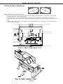
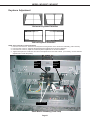
1
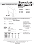
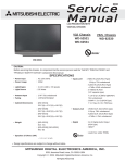
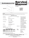
Ser vice
Manual
2004
MITSUBISHI ELECTRIC
DIGITAL LIGHT PROCESSING™ PROJECTION TV
VK26 CHASSIS
MODELS
WD-52327
WD-62327
WD-52327
CAUTION:
Before servicing this chassis, it is important that the service person read the "SAFETY PRECAUTIONS" and
"PRODUCT SAFETY NOTICE" contained in this manual.
SPECIFICATIONS
• Power Input
• Power Usage
• Light Engine
• Light Source
• Frequency Range
: AC 120V, 60Hz
: 200W
: DLP (1280 x 720p pixels)
: 120W VIP
: VHF 54 ~ 470MHz
UHF 470 ~ 806MHz
• Antenna Input
: VHF/UHF 75Ω unbalanced
2 - NTSC
• Cabinet Dimensions
WD-52327
: 37.2"(H) x 49.6"(w) x 17.4"(D)
WD-62327
: 43.7"(H) x 58.3"(W) x 19.9"(D)
• Weight
[WD-52327] 110 lbs
[WD-62327] 139 lbs
• Input Level
: VIDEO IN JACK (RCA Type)
1.0Vp-p 75Ω unbalanced
: AUDIO IN JACK (RCA Type)
-4.7dBm 43kΩ unbalanced
: S-VIDEO IN JACK
(Y/C separate type)
Y:1.0 Vp-p C:0.286Vp-p(BURST)
75Ω unbalanced
: COMP / Y, Cr, Cb (RCA Type)
Y: 1.0 Vp-p Cr, Cb: 700mVp-p
: DTV / Y(G), Pr(R), Pb(B), H, V
Y: 1.0Vp-p with sync 75Ω (BNC)
Pr, Pb: 700mV 75Ω
H, V: 3.0Vp-p 75Ω
• Output Level
: VIDEO OUT JACK (RCA Type)
1.0Vp-p 75Ω unbalanced
: AUDIO OUT JACK (RCA Type)
-4.7dBm 4.7kΩ unbalanced
• Digital
: MonitorLinkTM/DVI
• Speakers (8 Ohms 10W)
: 2-5 inch Coaxial
• Design specifications are subject to change without notice.
.
MITSUBISHI DIGITAL ELECTRONICS
AMERICA, INC.
9351 Jeronimo Road, Irvine, CA 92618-1904
Copyright © 2004 Mitsubishi Digital Electronics America, Inc.
All Rights Reserved
MODEL: WD-52327 / WD-62327
CONTENTS
INTRODUCTION ............................................................................................................................... 5
PRODUCT SAFETY NOTICE ........................................................................................................... 5
SAFETY PRECAUTIONS ................................................................................................................. 6
DISASSEMBLY
WD-52327 & WD-62327
Front Cabinet Components .................................................................................................... 7
Rear Cabinet Components ..................................................................................................... 8
CHASSIS REMOVAL
Chassis removal procedure .................................................................................................... 9
Shield Removal .................................................................................................................... 10
Chassis PWB locations ....................................................................................................... 11
Accessing the Lamp Ballast ................................................................................................ 12
OPTICAL ENGINE REPLACEMENT
Optical Engine Mounting ...................................................................................................... 13
Removing the Optical Engine ............................................................................................... 14
Removing DMD Heat Sensor ................................................................................................ 15
Removing Bottom Plate & Black Support Bracket. ............................................................... 15
Installing the Optical Engine ................................................................................................ 16
SERVICING THE LENTICULAR SCREEN AND FRESNEL LENS
Removal of the Lenticular Screen and Fresnel Lens ............................................................. 17
Installation of the Lenticular Screen and Fresnel Lens .......................................................... 19
ELECTRICAL ADJUSTMENTS
Equipment .................................................................................................................................... 20
Initial Setup (Option Menu) ............................................................................................................ 21
Main Menu Defaults ...................................................................................................................... 21
A/V Memory Defaults .................................................................................................................... 22
LED Indications ............................................................................................................................ 22
LED Dignostic Check .................................................................................................................... 23
Circuit Adjustment Mode ............................................................................................................... 23
Adjustment Items List ................................................................................................................... 25
Activating Internal Test Patterns .................................................................................................... 26
Adjustment Procedures ................................................................................................................ 27
Main & Sub Y level adjustments .......................................................................................... 27
Main & Sub Color level adjustments ..................................................................................... 27
White Balance Adjustments ................................................................................................. 28
Horizontal & Vertical Position adjustments .......................................................................... 28
Mechanical Adjustments ............................................................................................................... 29
Required Front Disassembly ................................................................................................ 29
Required Rear Disassembly ................................................................................................. 29
Picture Rotation Adjustment ............................................................................................... 30
Horizontal & Vertical Keystone Distortion adjustments ......................................................... 31
QUICK REFERENCE PART LIST ..................................................................................................... 32
Service Parts List ........................................................................................................................... 33
Screen Parts List ............................................................................................................................ 41
CIRCUITRY BLOCK DIAGRAMS
Standby power Supplies ....................................................................................................... 42
Switched Supplies ............................................................................................................... 42
Page 3
MODEL: WD-52327 / WD-62327
Switched DC to DC Supplies ............................................................................................... 43
Video/Color Signal Path ....................................................................................................... 44
Sound Signal Path ............................................................................................................... 45
Sync Signal Path ................................................................................................................. 46
Control Circuit (Commands, Serial Data & Reset) ................................................................ 47
Control Circuit (Status Inputs, OSD Insert & CCD Insert) ...................................................... 48
PWB-FORMAT Block Diagram ............................................................................................ 49
SCHEMATIC DIAGRAMS
BLOCK (PWB INTERCONNECTIONS) ......................................................................................... S1
1
Page 4
MODEL: WD-52327 / WD-62327
INTRODUCTION
This service manual provides service instructions for PTV models WD-52327 and WD-62327, using the VK26 chassis.
This service manual includes:
1. Assembly and disassembly instructions for the front and rear cabinet components.
2. Servicing of the Lenticular Screen and Fresnel Lens.
3. Servicing to PWB level. The Optical Engine and Lamp Ballast are considered replaceable components.
4. Electrical and Mechanical adjustments.
5. Chip parts replacement procedures.
6. Simplified signal path block diagrams.
The parts list section of this service manual includes:
1. Cabinet and screen parts.
2. Electrical parts.
Block diagrams of the above listed models are included in this service manual for better understanding of the circuitry.
PRODUCT SAFETY NOTICE
Many electrical and mechanical parts in television receivers have special safety related characteristics. These characteristics are often not evident from visual inspection nor can the protection afforded by them necessarily be obtained by
using replacement components rated for higher voltage, wattage, etc.
Replacement parts which have special safety characteristics are identified in this service manual.
Electrical components having such features are identified by shading on the schematic diagram and by bold type in
the parts list of this service manual. Therefore, the replacement for any safety part should be identical in value
and characteristics.
Page 5
MODEL: WD-52327 / WD-62327
SAFETY PRECAUTIONS
NOTICE:
WARNING:
1.
2.
Observe all cautions and safety related notes located inside the receiver cabinet and on the
receiver chassis.
Operation of this receiver outside the cabinet or with the cover removed presents a shock hazard
from the receiver's power supplies. Work on the receiver should not be attempted by anyone who is
not thoroughly familiar with the precautions necessary when working on high voltage equipment.
When service is required, observe the original lead dress. Extra precaution should be taken to
assure correct lead dress in the high voltage area. Where a short-circuit has occurred, replace those
components that indicate evidence of overheating.
WARNING ... RISK OF EYE INJURY
Do not look into the light source, Light Engine lens or mirror when operating the TV
Leakage current check
Before returning the receiver to the customer, it is recommended that leakage current be measured according to the
following methods.
1. Cold Check
With the alternating current (AC) plug removed from the AC source, place a jumper across the two AC plug
prongs. Connect one lead of an ohm meter to the AC plug and touch the other lead to each exposed metal part
(i.e. antennas, handle bracket, metal cabinet, screw heads, metal overlay, control shafts, etc.), particularly any
exposed metal part that has a return path to the chassis. The resistance of the exposed metal parts having a
return path to the chassis should be a minimum of 1Mega Ohm. Any resistance below this value indicates an
abnormal condition and requires corrective action.
2. Hot Check ...Use the circuit shown below to perform the hot check test.
1. Keep switch S1 open and connect the receiver to the measuring circuit. Immediately after
connection, and with the switching devices of the receiver in their operating positions, measure the
leakage current for both positions of switch S2.
2. Close switch S1, energizing the receiver. Immediately after closing switch S1, and with the
switching devices of the receiver in their operating positions, measure the leakage current for both
positions of switch S2. Repeat the current measurements of items 1 and 2 after the receiver has
reached thermal stabilization. The leakage current must not exceed 0.5 milliampere (mA).
Page 6
MODEL: WD-52327 / WD-62327
CABINET DISASSEMBLY (FRONT VIEW)
WD-52327 / WD-62327
*Refer to the Parts List for Part Numbers
Front Cabinet Disassembly
1.
2.
3.
4.
5.
6.
Remove the SPEAKER-GRILLE by pulling forward.
Remove screws (a) to remove the COVER-FRONT.
Remove screws (b) on the rear of the upper back cover (4 across the top and 3 on each side).
Remove the 4 screws (c) holding the bottom of the Screen Assembly.
Unplug connector LN from the Control Panel.
Lift the Screen Assembly up slightly then pull towards the front to remove the assembly.
Page 7
MODEL: WD-52327 / WD-62327
REAR DISASSEMBLY
FILTER-COVER Removal
Remove 2 screws (d) to remove the Filter Cover.
COVER-BACK Removal
1)
2)
3)
4)
Remove 9 screws (a)
Remove 6 screws (b)
Remove 2 screws (c)
Pull the COVER-BACK
from the cabinet.
NOTE: To operate the TV with the COVER-BACK removed,
the FILTER-COVER must be reinstalled.
Rear Plate Removal
1)
2
3)
4)
Remove 6 screws (a)
Remove 6 screws (b)
Pull the COVER-BACK from the cabinet.
Lay the Rear Plate down behind the TV.
Page 8
MODEL: WD-52327 / WD-62327
CHASSIS REMOVAL
Chassis Removal Procedure
1)
2)
2)
3)
Disconnect all relay connectors shown below (JE, CC, JJ, PP, LL & EE)
Disconnect the J9 and DVI connectors at the Optical Engine.
Remove three screws (a) securing the chassis.
Carefully slide the chassis from the cabinet.
Page 9
MODEL: WD-52327 / WD-62327
Shield Removal
1) To remove SHIELD-COVER, remove 11 screws (a).
2) To remove PWB-TERMINAL COVER, remove 9 screws (b).
Page 10
MODEL: WD-52327 / WD-62327
VK26 Chassis PWB Locations (Shield-Cover removed)
Page 11
MODEL: WD-52327 / WD-62327
Accessing The Lamp Ballast
Removing the Right Support (Rear View)
1) Remove the Air Filter.
2) Remove the 3 screws (a).
3) Lift the upper cabinet slightly
to remove the support bracket.
Lift upper cabinet
slightly to remove
support.
(a)
Remove
Air Filter
Unplug CJ3 & CN2
Connectors
Unplug
Connectors
Removing the Lamp Ballast Shield
(4 screws)
4 Screws
Page 12
MODEL: WD-52327 / WD-62327
OPTICAL ENGINE REPLACEMENT
Optical Engine is mounted on the Adjuster assembly as shown below.
1)
2)
3)
4)
5)
The Optical Engine is secured to the bottom plate with 4 screws (b).
The Black Bracket is secured to the bottom plate and the Lamp Cartridge Housing with 4 screws (c).
Tab (1) on the bottom plate slides into slot (1) on the Adjuster assembly.
4 screws (a) secure the bottom plate and Optical Engine to the Adjuster assembly.
The Optical Engine, the bottom plate, black bracket and the Optical Engine are removed as a unit.
Page 13
MODEL: WD-52327 / WD-62327
Removing the Optical Engine
1)
2)
3)
4)
Remove the Cabinet BACK-BOARD and REAR-PLATE (refer to disassembly instructions).
Disconnect all connectors connected to the Engine and the PWB-FORMAT.
From the rear of the TV, remove the 4 screws (c), to remove the COVER-DUCT and DMD Fan cover.
From the rear of the TV, remove the 4 screws (a), shown below, securing the bottom plate to the Adjuster
assembly.
5) Slide the Optical Engine, PWB-DMD and bottom plate towards the rear to remove the unit from the TV.
(a)
Optical Engine (Rear View / Airduct & DMD Fan Cover Removed)
Page 14
MODEL: WD-52327 / WD-62327
Remove the follolwing parts from the Optical Engine
•
•
DMD Thermal Sensor
The Optical Engine bottom plate and black bracket
DMD Termal Sensor Removal (Figure 1)
1) Remove screw (a) on the top of the DMD Fan.
2) Set the Thermal Sensor aside to install on the replacement Optical Engine.
(a)
Thermal
Sensor
Heat Sensor
Figure 1: DMD Thermal Sensor
Bottom Plate & Black Bracket Removal
1) Remove the 4 screws (B) from the Bottom Plate (Figure 2)
2) Remove the two screws (c), holding the Black Bracket to the Lamp Cartridge Housing. (Figure 3)
Bottom Plate
(B)
Bottom View
Figure 2: Bottom Plate
Page 15
MODEL: WD-52327 / WD-62327
Black Bracket
(C)
Front View
Figure 3: Black Support Bracket
Installing the Optical Engine
1) Install the Bottom Plate, Black Support Bracket and the Thermal Sensor from the original Optical Engine, on
the replacement Engine
2) Reverse the removal procedure to install the replacement Optical Engine in the cabinet.
2) The following adjustments may have to be performed after the installation.
• Horizontal and Vertical Electrical Centering Adjustment.
• Optical Unit Rotation Adjustment
• Optical Unit Keystone Distortion Adjustments.
Page 16
MODEL: WD-52327 / WD-62327
SERVICING THE LENTICULAR SCREEN AND FRESNEL LENS
CAUTION:
Wear gloves when handling the Lenticular Screen and Fresnel Lens.
This prevents cuts and finger prints. Do not place Fresnel Lens in the sun.
This may cause fire and heat related injuries.
Lenticular Screen and Fresnel Lens Removal
1.
2.
3.
4.
Remove the screen assembly shown in the Cabinet Disassembly procedure.
Remove the four screws (a) to remove the bottom of the SCREEN-FRAME-BOTTOM . (Figure 1)
From the front of the screen assembly, slide the BEZEL out the bottom of the Screen Frame. (Figure 2)
From the rear of the screen assembly, carefully slide the Lenticular Screen and Fresnel Lens combination
from the Screen Frame. (Figure 3)
Note: When separating the Lenticular Screen from the Fresnel Lens, use caution
while prying the Screen and Lens apart. Use a slot type screw driver, and
remove the pressure sensitive double sided tape.
Figure 1: SCREEN-FRAME-BOTTOM Removal (Rear View)
Page 17
MODEL: WD-52327 / WD-62327
Figure 2: BEZEL Removal (Front View)
Figure 3: Lenticular Screen & Fresnel Lens Removal (Rear View)
Page 18
MODEL: WD-52327 / WD-62327
SERVICING THE LENTICULAR SCREEN AND FRESNEL LENS
Lenticular Screen and Fresnel Lens Installation
Note: Store the Lenticular Screen and Fresnel Lens in a cool dry place. High humidity may
deform the Lenticular Screen and Fresnel Lens.
1. Apply double coated tape (Part #LENS-TAPE) along the top rear edge of the Lenticular Screen, as shown
below. Refer to the table below for the tape length.
2. Sandwich the Fresnal Lens and Lenticular Screen together. The Lenticular Screen label must be towards
the front and the Fresnel Lens label towards the rear. (Figure 4)
3. Apply pressure at the top edge to bond the screens together.
4. Reverse the Screen Removal procedure and insert the screens in the Screen Fame Assembly.
Figure 4: Installing the Fresnel Lens & Lenticular Screen
*X INCHES - Refer to the Tape Length in the table below
MODEL
WD-52327
WD-62327
SCREEN SIZE
52 Inches
62 Inches
Page 19
TAPE LENGTH
46.3 Inches
55.1 Inches
MODEL: WD-52327 / WD-62327
ELECTRICAL ADJUSTMENTS
Note: Perform only the adjustments required.
Do not attempt an alignment if proper equipment is not available.
Test Equipment
•
•
Oscilloscope (Unless otherwise specified, use 10:1 probes)
Signal Generator (NTSC Color Bar)
Test Signals
A. Internally Generated Square Pattern Signals
B. Color Bar Signal
Use the color bar signal shown
below, unless otherwise specified
in this manual.
100%
75%
40%
40%
1H
Split-Field Color Bars (100% window)
Page 20
MODEL: WD-52327 / WD-62327
Initial Setup
A. Option Menu Setup
Follow the steps below for the initial set-up:
1. Select the "MENU" display by pressing the "MENU" button once.
2. Press the number buttons "5", "7", "7", "0" in sequence to select the "OPTION MENU" display.
3. Press the "ADJUST" button to select "INITIALIZE."
4. Press "ENTER."
NOTE: At this time channel 3 is automatically selected.
OPTION MENU <MENU> <5-7-7-0>
Initialize
Power Restore:
DTV Port:
Direct Key Mode:
Lamp Hours: TOTAL
0
Total TV
On Time
B.
Off
AUTO
Off
CURRNT PREV1
0
0
Current
Lamp
Time
Previous
Lamp
Time
PREV2
0
Previous
Lamp
Time 2
Default Settings
VK26 M ain M enu Default Settings
Se tup Me nu
M emoriz e Channels
Ant-A
Language
English
E nergy Mode
Standard
Input Assignm e nt Me nu
A ntenna-A
On
A ntenna-B
On
DTV
YPrP b
Component-1
Comp-1
Component-2
Comp-2
Input-1
Input-1
Input-2
Input-2
Input-3
Input-3
M onitorLink™
MonoLink
Clock Me nu
Clock S etting
Manual
Clock Time
../..
S et Day
Sunday
Time Zone
N/A
Daylight Savings
N/A
Ca ptions
Closed Captions
In Mute
CC Bac kground
Gray
Cha nne l Edit Me nu
A ntenna
Ant-A
Channel
003
M emory
Deleted
Name
N/A
S QV
N/A
V-Chip Lock Me nu
Lock by Time
On
Lock Tim e
N/A
Unlock Time
N/A
Front Button Lock
Off
V-Chip M e nu
V -Chip
Off
TV Rating
TV-PG
FV-Fantasy Violence
A llow
D-Sexual Dialog
A llow
L-Adult Language
A llow
S -Sexual Situation
A llow
V -Violence
A llow
M ovie Rating
PG
P rogram s Not Rated
A llow
V-Chip Hours
V -Chip S tart Tim e
12:00am
V -Chip S tart Tim e
12:00am
Adva nce d Fe a ture s M e nu
Color Balance
Timer
V ideo M ute
On
B lack Enhancementt
On
Color Ba la nce Me nu
A nt-A Auto Color Correction
Off
P erfectColor™
Reset Color for Ant-A
Tim e r M e nu
Timer
Off
S et Time
12:00 AM
S et Day
Every day
Input
Ant-A
Channel
003
Pe rfe ctColor™
M agenta
50%
Page 21
Red
50%
Yellow
50%
Green
50%
Cyan
50%
Blue
50%
Audio/Vide o Se ttings M e nu
A/V M emory Reset
Ant-A
TV Speakers (internal)
On
Audio Output
Fix ed
Audio Se ttings (TV )
Bass
50%
Treble
50%
Balanc e
Center
Surrond
Off
Listen To
Stereo
Level S ound
Off
TV Volume
30%
Vide o Se ttings (TV )
Contrast
50%
Brightness
50%
Sharpness
50%
Color
50%
Tint
50%
Color Temp.
High
Video Noise
Standard
Film M ode (A uto)
On
P IP Me nu
PIP Souce
A nt-A Ch-3
PIP Position
Lower Rt.
POP P osition
Rt. Half
PIP/POP Form at
Dble W in.
Stretc h
Form a t
MODEL: WD-52327 / WD-62327
A/V Memory Defaults
Function
Contrast
Brightness
Sharpness
Color
Tint
Color Temp.
Video Noise
Film Mode
Bass
Treble
Balance
Surround
Listen To
Level Sound
Ant -A/B
DTV
Maximum Maximum
Center
Center
Center
Center
Center
Center
Center
Center
High
High
Standard Standard
On
On
Center
Center
Center
Center
Center
Center
Off
Off
Stereo
N/A
Off
Off
Comp-1/2
Maximum
Center
Center
Center
Center
High
Standard
On
Center
Center
Center
Off
N/A
Off
Input 1/2/3 MonoLink
Maximum Maximum
Center
Center
Center
Center
Center
Center
Center
Center
High
High
Standard
Standard
On
On
Center
Center
Center
Center
Center
Center
Off
Off
N/A
N/A
Off
Off
C. A/V Memory
Each of the external inputs has its’ own Audio/Video Memory. A change in an A/V setting at a specific input is
stored in memory for that specific input.
A/V Reset
1. The front panel AV Reset button initializes all A/V Memories.
2. The AV Reset in the user’s menu initializes only the selected input’s A/V Memory.
LED Indications
The three front panel LEDs provides an indication of the sets operation,
and the possible cause of a malfunction.
Normal LED Indications
Power/Timer
Off
Green Blink
Off
Green
Slow Green Blink
LED
Status
Off
Off
Off
Off
Off
Lamp
Off
Off
Blink green
Off
Off
Condition
Off (standby)
µPC Initializing (after AC off/on) (1~2 sec)
Lamp Fan running (1 min after PTV Off)
Power On
Power On Timer is set.
Lamp
Off
Yellow
Blink Yellow
Off
Red
Off
Off
Condition
Temp. high - dirty filter/excess room temp.
4000 hrs. Lamp usage warning
Lamp Cover open
Air Filter Cover open
Lamp failure (failed to turn On or broken)
Fan Stopped
Circuit failure (short) or DVI cable disconnected
Abnormal LED Indications
Power/Timer
Off
Off
Off
Off
Off
Off
LED
Status
Yellow
Off
Off
Blink Yellow
Off
Blink Red
Red
Page 22
MODEL: WD-52327 / WD-62327
LED Diagnostic Check
1. Initial Control Circuitry Check
Immediately after the TV is connected to an AC power source:
2. Error Code Operational Check
Pressing the front panel “INPUT” and “MENU” buttons at the same time, and holding for 5 seconds,
activates the Error Code Mode. The ” Power LED” flashes denoting a two digit Error Code, or indicating no problem
has occured since the last Initalization.
Note: The front panel buttons must used, NOT those on the Remote Control.
•
•
•
•
The number of flashes indicates the value of the MSD (tens digit) of the Error Code.
The flashing then pauses for approximately 1/2 second.
The LED then flashes indicating the value of the LSD (ones digit) of the Error Code.
The Error Code is repeated a total of 5 times.
Example: If the Error Code is “34”, the LED will flash 3 times, pause, and then flash 4 times.
3. Error Codes
The Error Code designations indicating a malfunction, or no malfunction, are listed below:
ERR0R CODES
Error
Code
12
32
33
34
36
37
38
39
41
44
Description
No Error detected, check Power Supply
Lamp Cover is open
Air Filter Cover is open
Lamp abnormality
Light Engine (DMD or LAMP Fan stopped)
Exhaust or Lamp Ballast Fan stopped
Lamp temperature high
DMD temperature high
Short is detected
DVI cable between FMT & Engine disconnected.
Circuit Adjustment Mode
Most of the adjustments can only be performed using the remote hand unit.
A. Activating the Circuit Adjustment Mode
1. Select the signal source.
2. Press the "MENU" button on a remote hand unit.
3. Press the number buttons "5", "7", "5", "7" in sequence. The screen will change to the Adjustment Mode.
Note: Repeat steps 1 and 2 if the circuit
adjustment mode does not appear
on screen.
Page 23
MODEL: WD-52327 / WD-62327
B. Selection of adjustment Functions and
Adjustment Items
To select an adjustment item in the circuit adjustment mode, first select the
adjustment function that includes the specific item to be adjusted. Then
select that adjustment item.
Refer to the following pages for the listing of
adjustment functions and adjustment items.
1. Press the "AUDIO" button on a remote hand unit to select an adjustment function. Each time the button is pressed, the Function changes
in the following sequence:
MAIN MATR
SUB MATR
Adjustment Functions
DDP
FPGA
MISCDEV
2. Press the “VIDEO” button to select a specific
Adjustment Item. The Item number increases
each time the “VIDEO” button is pressed.
C. Changing Data
After selecting an adjustment Item, use the “ADJUST UP/DOWN” buttons to
change data.
• Press “ADJUST DOWN” to decrease the data value.
• Press “ADJUST UP” to increase the data value.
D. Saving Adjustment Data
Press “ENTER” to save adjustment data in memory. The character display turns red for approximately one
second in this step.
Note: If the circuit adjustment mode is terminated without pressing “ENTER”, changes in adjustment data
are not saved.
E. Terminating the Circuit Adjustment Mode
Press the “MENU” button on the remote hand unit twice to terminate the adjustment mode.
Note: The circuit adjustment mode can also be terminated by turning power OFF.
Page 24
MODEL: WD-52327 / WD-62327
List of Service Adjustment Items
MAIN MATRIX
(Main Decoder)
Stored in IC2K02 on PWB-TERMINAL
Item No. Abbrev,
Description
Data Range Initial Data
39
SCNT Main Y-Gain
0~31
16
41
SCLR Main CB/CR Gain
0~31
22
SUB MATRIX
(Sub Decoder)
Stored in IC2K02 on PWB-TERMINAL
Item No. Abbrev,
Description
Data Range Initial Data
39
SCNT Sub Y-Gain
0~31
15
41
SCLR Sub CB/CR Gain
0~31
21
FPGA
Item No.
1
2
Stored in IC7C01 on PWB-SIGNAL
Abbrev,
Description
Data Range Initial Data
H-DLY Horiz. Position
0~128
74
V-DLY Vertical Position
0~55
32
DDP Function
Item #
120
121
122
123
124
125
126
127
128
Abbrev.
GGH
GRH
GBH
GGM
GRM
GBM
GGL
GRL
GBL
Description
High Temp. Green Gain
High Temp. Red Gain
High Temp. Blue Gain
Mid Temp. Green Gain
Mid Temp. Red Gain
Mid Temp. Blue Gain
Low Temp. Green Gain
Low Temp. Red Gain
Low Temp. Blue Gain
NOTE: Data values are in hexadecimal format
Page 25
Stored in IC2K02 on PWB-TERMINAL
Data
Initial Data
Range
WD-52327
WD-62327
000~400
2FA
31F
"
400
400
"
36D
34F
"
2E1
2FE
"
400
400
"
320
2FF
"
2C8
2EC
"
400
400
"
2D4
2C0
MODEL: WD-52327 / WD-62327
Activating & Selecting an Internal
Test Signal
1. Select an External Input with no signal.
2. Press the buttons “MENU”-“5”-“7”-“5”-“7” in
sequence. (Activates the Service Menu)
3. Select the “FPGA” function (AUDIO button)
4. Press
“1” for Pattern A, or “2” for Pattern B.
.
5. Press “9” to return to the Service Menu.
6. Press “MENU” to exit the Service Mode.
CAUTION
DO NOT press “MENU” (or HOME) without
pressing “9” first. (The Video Mute function will
not function properly.)
To correct the Mute function -- remove AC to
the TV, then reapply AC to reset the unit.
Page 26
MODEL: WD-52327 / WD-62327
[Video Circuit]
Purpose:
To set picture luminance
1. Main/Sub Y Level
Symptom:
Excess or insufficient brightness.
Measuring
Instrument
Oscilloscope
Test Point
JA-22 & JB-3
Ext. Trigger
------
Measuring
Range
------
Input Signal
Color Bars
Input Terminal
Video Input
CIRCUIT ADJUST MODE
Activate …….. MEN U-5-7-5-7
Function … ...…… …..AUD IO
Item No. …… ….…….VIDEO
Adjus t Data ….…….AD JU ST
Save Data …. ……… ENTER
Exit ……… …..MEN U (twice)
1.
2.
3.
4.
5.
6.
7.
8.
9.
10.
11.
12.
Supply a color bar signal to a Video Input (not an RF input).
Select the color bar signal for both the main and sub pictures.
Connect the oscilloscope to connector JA pin 22. (Main-Y)
Activate the Adjustment Mode (MENU-5-7-5-7)
Select the “MAIN MTRX” function. (AUDIO button)
Select adjustment Item “39 SCNT”. (VIDEO button)
Adjust the data for 0.71 ~ 0.76 Vp-p at JA pin 22.
(If it cannot be adjusted within this range, set to the lower value)
Move the oscilloscope to connector JB pin 3. (Sub-y)
Select the “SUB MTRX” function. (AUDIO button)
Select adjustment Item “39 SCNT”. (VIDEO button)
Adjust the data to equal the MAIN-Y Gain (+0.0V -0.05V).
Press “ENTER” to save data changes.
[Video Circuit]
Purpose:
To set the sub picture color level.
2. Main/Sub Color Level
Symptom:
Main and sub pictures color levels differs.
Measuring
Instrument
Oscilloscope
Test Point
JA-20 & JB-5
Ext. Trigger
------
Measuring
Range
200mV/div
20usec/div
Input Signal
Input Terminal
1.
2.
3.
3.
4.
5.
6.
Color Bars
Video Input
7.
8.
9.
10.
11.
Supply a color bar signal to a Video Input.
Select the color bar signal as the source for both the main and sub picture.
Connect an oscilloscope to connector JA pin 20 (main Cr).
Activate the Adjustment mode (MENU-5-7-5-7)
Select the “MAIN MTRX” function (AUDIO button).
Select adjustment item “41 SCLR” (VIDEO button)
Adjust the data for 0.81 ~ 0.86 Vp-p min. at JA pin 20.
(If it cannot be adjusted within this range, set to the lower value).
Move the oscilloscope to connector JB pin 5 (sub Cr).
Select the “SUB MTRX” function (AUDIO button).
Select adjustment item “41 SCLR” (VIDEO button).
Adjust data so the Sub Cr amplitude equals that of the Main Cr.
Press “ENTER to save data changes.
Page 27
MODEL: WD-52327 / WD-62327
[Video Circuit]
Purpose:
3. White Balance
Symptom:
Measuring
Instrument
Ext. Trigger
------
1.
3.
4.
5.
Measuring
Range
------
6.
Input Signal
White Raster
7.
Test Point
Input Terminal
Video Input
8.
9.
10.
To set high, mid and low temperature white levels.
White areas have a color tint.
Supply a 100% white raster to an External Video Input.
Activate the Service Mode. (MENU-5-7-5-7)
Select the “DDP” function. (AUDIO button)
Select adjustment Items with the VIDEO button.
NOTE: Data is displayed in the hexadecimal format.
Adjust the data for Items “120 GGH”, “121 GRH and “122 GBH” for optimum
white at the center of the screen.
Adjust the data for Items “123 GGM”, “124 GRM and “125 GBM” for optimum
white at the center of the screen.
Adjust the data for Items “126 GGL”, “127 GRL and “128 GBL” for optimum
white at the center of the screen.
Press “ENTER” to save data changes.
Press “MENU” twice to exit the Service Mode.
CIRCUIT ADJUST MODE
Activate …….. MEN U-5-7-5-7
Function … ...…… …..AUD IO
Item No. …… ….…….VIDEO
Adjus t Data ….…….AD JU ST
Save Data …. ……… ENTER
Exit ……… …..MEN U (twice)
[PICTURE POSITION]
Purpose:
To center picture on the screen.
4. Horizontal/Vertical Position
Symptom:
Picture is off center.
Measuring
Instrument
----
NOTE: The TV must be on a flat level surface.
Test Point
----
Ext. Trigger
------
Measuring
Range
-------
Input Signal
Input Terminal
Internal Pattern “B”
External Input
1.
2.
3.
4.
5.
6.
7.
8.
9.
10.
11.
12.
Select an External Input with no signal.
Press “MENU-5-7-5-7” in sequence (activates the Service Mode).
Press “AUDIO” to select the “FPGA” function.
Press “2” to activate internal Test Pattern B. (Shown below)
Use the “VIDEO” button to select Item “1 H-DLY”.
Use the “ADJUST” buttons to center the picture Horizontally..
Press “ENTER” to save the adjustment.
Use the “VIDEO” button to select Item “2 V-DLY”.
Use the “ADJUST” buttons to center the picture Vertically.
Press “ENTER” to save the adjustment.
Press “9” to terminate the test pattern.
Press “Menu” twice to terminate the Adjustment Mode.
CIRCUIT ADJUST MODE
Activate …….. MENU-5-7-5-7
Function …...………..AUDIO
Item No. ……….…….VIDEO
Adjust Data ….…….ADJUST
Save Data …. ………ENTER
Exit ………….."9" then "MENU"
Page 28
MODEL: WD-52327 / WD-62327
Mechanical Adjustments
•
•
To perform the mechanical adjustments, the TV must be on a flat level surface and a certain amount of disassembly
is required.
Use internal Test Pattern B for all mechanical adjustments.
Front Disassembly
Refer to the diagram below for the Front Panel removal procedures.
Rear Disassembly
Refer to the to the diagrams below for the COVER-BACK and Rear Plate removal.
NOTE: To operate the TV with the COVER-BACK removed,
the FILTER-COVER must be reinstalled and the Exhaust Fan connected.
Page 29
MODEL: WD-52327 / WD-62327
Picture Rotation Adjustment
NOTE: The TV must be on a flat level surface.
1. From the front of the TV, lift the foam to access and loosen slightly, the brass Rotation Locking Screws on the Adjuster
Assembly, Figure 4A. (Use a 10mm wrench.)
2. From the rear of the TV, access the black Rotation Adjustment screw and adjust so the test pattern center lines are
parallel to the sides, top and bottom of the screen frame, Figure 4B. (Use a mirror to veiw the picture from the rear of the
set.)
3. Tighten the two Locking Screws. Use Locktite to secure the Adjustment Screw. (If necessary, use the electrical adjustments to center the picture)
Page 30
MODEL: WD-52327 / WD-62327
Keystone Adjustment
Horizontal Keystone Distortion
Vertical Keystone Distortion
NOTE: The TV must be on a flat level surface
1. From the front of the TV, loosen the two Keystone Locking Screws in the small mirror assembly. (10mm wrench)
2. From the front of the TV, adjust the Horizontal Keystone Adjustment for minimum distortion.
3. From the front of the TV, adjust the Vertical Keystone Adjustment for minimum distortion.
4. Tighten the Keystone Lock Screws. and secure the adjustment screws with Locktite. (If necessary, use the electrical
adjustments to center the picture)
Horiz
Keystone
Adjust
Vertical
Keystone
Adjust
Locking Screws
Small Mirror Assembly (Front View)
Page 31
MODEL: WD-52327 / WD-62327
QUICK REFERENCE FOR COMMON REPLACEMENT PARTS
• Critical Electrical Components are indicated by Bold Type in the Parts List
Customer Replaceable Parts
P a rt Na m e
La m p Ca rtridge
Dust Filter
Rem ote Control
De scription
LAMP -CARTRIDGE
FILTER-DUST
REMOTE
P a rt Na m e
Optical Engine
La m p Ba lla st
P ower PW B
S ignal PW B
Format PW B
Terminal PW B
S ub Power PW B
A udio PW B
Rem ote Preamp
Front PW B
Control PW B
Right Speaker PW B
Left S peaker PW B
La m p Fa n
DMD Fa n
Ba lla st Fa n
Ex ha ust Fa n
DMD Thermal Sensor
Lamp Cover Detect Switch
Filter Cover Detect Switch
De scription
OPTICAL-ENGINE
UNIT-POW ER-LAMP
ASSY-PW B-POW ER
ASSY-PW B-SIGNAL
ASSY-PW B-FMT
ASSY-PW B-TERMINAL
ASSY-PW B-POW ER-SUB
ASSY-PW B-AUDIO
ASSY-PW B-PREAMP
ASSY-PW B-FRONT
ASSY-PW B-CONTROL
ASSY-PW B-SPEAKER-R
ASSY-PW B-SPEADER-L
FAN-LAMP
FAN-DMD
FAN-BALLAST
FAN-EXHAUST
SENSOR-THERMAL
SW -M ICRO
SW -M ICRO
W D-52327
915P020010
620D144010
260P116010
W D-62327
915P020010
620D144010
260P116010
W D-52327
939P977010
939B978010
930B929001
930B930001
930B931001
930B932001
934C148001
934C149001
935D811001
935D812001
935D813001
935D814001
935D815001
299P282010
299P283010
299P278020
299P103050
299P280010
436P021010
436P021010
W D-62327
939P977020
939B978010
930B929001
930B930001
930B931001
930B932001
934C148001
934C149001
935D811001
935D812001
935D813001
935D814001
935D815001
299P282010
299P283010
299P278020
299P103050
299P280010
436P021010
436P021010
W D-52327
491P176030
491P175010
761A252010
W D-62327
491P176040
491P175020
761A253010
Service Parts
Screen Parts
P a rt Na m e
Lenticular Screen
Fresnel Lens
B ezel
De scription
LENS-LENTICULAR
LENS-FRESNEL
BEZEL-FRONT
PAGE 32
MODEL: WD-52327 / WD-62327
Model Legend: [a] WD-52327, [b] WD-623275
Ref #
Part #
Part Name & Description
INTEGRATED CIRCUITS
IC2D00
IC2D02
IC2D04
IC2K01
IC2K02
IC2K04
IC2K05
IC2L01
IC2M01
IC2M02
IC2MD1
IC2N01
IC2P01
IC2R01
IC3A01
IC3E00
IC3J01
IC3J02
IC3J03
IC3J04
IC7A00
IC7A02
IC7A03
IC7A05
IC7A06
IC7AAA
IC7C01
IC7D01
IC7D02
IC7D03
IC7E00
IC7E01
IC7E02
IC7E03
IC7H00
IC7H07
IC7M00
IC7N01
IC7N11
IC7N21
IC7N31
IC7N41
IC7N61
IC8C03
IC8D01
IC8D02
IC8E00
IC8E02
IC8E03
IC8E04
IC8E05
IC8H01
IC8H02
IC9A10
IC9A12
IC9A20
IC9A21
IC9AAA
270P974010
261P135010
271P004010
270P623010
275P533010
275P718010
275P718010
275P937010
275P947010
270P992020
272P379020
275P938010
275P938010
271P005020
275P731020
271P080010
270P838010
270P838010
270P838010
270P838010
276P017070
270P706020
275P786010
271P023010
271P023010
275P981010
275P533010
275P278010
270P818020
267P172010
275P451010
275P560010
275P560010
275P560010
275P963010
270P992010
275P982010
270P348010
275P236020
275P769010
275P769010
274P901010
274P901010
275P689010
271P112010
275P982010
276P107010
270P879030
270P879030
271P010010
271P010010
271P113010
271P114020
267P175010
271P081010
270P816010
270P991010
270P677010
IC-C-MOS - SII907B
FET-HEX - IRF7313
IC - CM1208-08MS
IC - CXA2069Q
IC-C-MOS - M24C64WM6T
IC-C-MOS - TC74HC4053FT
IC-C-MOS - TC74HC4053FT
IC-C-MOS - MM1519XQ
IC-C-MOS - UPD64083
IC - BA25BC0FP
IC - LM1881MX (NSC)
IC-C-MOS - TA1340F
IC-C-MOS - TA1340F
IC - AN15851AN
IC-C-MOS - MSP3445G-QI-B8-V3
IC - TDA8922J
IC-C-MOS - NJM2520M
IC-C-MOS - NJM2520M
IC-C-MOS - NJM2520M
IC-C-MOS - NJM2520M
IC-C-MOS - M306V7FGFP-VK26
IC - MAX823REUK
IC-C-MOS - TC7SA08FU
IC - SN74CBTD1G125DBVR
IC - SN74CBTD1G125DBVR
IC-C-MOS - 24LCS22AT/SN
IC-C-MOS - M24C64WM6T
IC-C-MOS - TC74LVX14FT
IC - CXA3506R
HIC - AF-9395A
IC-C-MOS - TC74HC4066AFN
IC-C-MOS - ADS931E
IC-C-MOS - ADS931E
IC-C-MOS - ADS931E
IC-C-MOS - DPM5
IC - BA18BC0FP
IC - MT48LC2M32B2-7
IC - TLC2932IPW
IC-C-MOS - TC74LVX244FT
IC-C-MOS - TC74AC157FT
IC-C-MOS - TC74AC157FT
IC-C-MOS - TC74HCT7007AF
IC-C-MOS - TC74HCT7007AF
IC-C-MOS - ICS551MT
IC - IP00C722
IC - MT48LC2M32B2-7
IC-C-MOS - SiI164
IC - SC1566I5M-2.5TR
IC - SC1566I5M-2.5TR
IC - RT9172-18CG
IC - RT9172-18CG
IC - XC2S50E-6PQ208C
IC - XCF01SVO20C-K261
HIC - STR-W6735
IC - BA00CC0WFP
IC - NJM431L
IC - IRU3037CS
IC - BA033FP
[#]
Ref #
IC9C01
IC9C11
IC9C20
IC9C21
IC9C21
IC9C31
IC9C61
Part #
Part Name & Description
270P928010
270P928010
267P164010
270P677010
270P816010
270P999010
270P677010
IC - BA17809FP
IC - BA17809FP
HIC - TNY264P
IC - BA033FP
IC - NJM431L
IC - NJM2370R09
IC - BA033FP
TRANSISTORS
CHIP Type Transistors (Listed by Part No.)
Part No.
Description
260P806010 DTA124EK/UN2112
260P817010 2SA1037K-Q
260P817050 2SA1037K-R,S/2SB709AI-R,S
260P817080 2SA1037K-R,S
260P818010 2SC2412K-Q
260P818050 2SC2412K-R,S/2SD601AI-R,S
260P835030 2SC2413K-Q
260P846030 DTC143ZKAT146
TRANSISTORS
Ref #
Q9A20
Q9A70
Q9B70
Conventional
Part #
261P135010
261P101010
261P101010
D2J91
D7A00
D7AAA
D7L20
D7L21
D7L22
D7L23
D7L24
D7L25
D7L26
D7L27
D9A00
D9A01
D9A02
D9A03
D9A04
D9A05
D9A06
D9A18
D9A19
D9A20
D9A23
D9A24
D9A25
D9A26
D9A27
D9A28
D9A29
D9A30
D9A31
D9A32
262P075010
264P828010
262P805050
262P075010
264P212020
264P584020
264P584020
262P075010
262P075010
262P075010
262P075010
262P031010
262P031010
264P045080
264P461050
264P045080
264P899010
264P045080
264P045080
264P045080
264P045080
264P045080
264P045080
264P045080
262P066010
262P066010
264P045080
264P045080
264P470070
264P828010
264P828010
Transistors (By Ref #)
Part Name & Description
FET-HEX - IRF7313
TR - PHP21N06T
TR - PHP21N06T
DIODES
PAGE 33
DIODE - RSB6.8S
D-CHIP - DAN202U/MA142WK
D-CHIP - UDZS5.1B
DIODE - RSB6.8S
D-LED - LN31GPH
DIODE-LE - SML1216W-C,D
DIODE-LE - SML1216W-C,D
DIODE - RSB6.8S
DIODE - RSB6.8S
DIODE - RSB6.8S
DIODE - RSB6.8S
DIODE - D6SB80
DIODE - D6SB80
DIODE - 1S2076A/1S2471OM
DIODE - EQA02-06B/RD5.6EB3
DIODE - 1S2076A/1S2471OM
DIODE - BYV26E
DIODE - 1S2076A/1S2471OM
DIODE - 1S2076A/1S2471OM
DIODE - 1S2076A/1S2471OM
DIODE - 1S2076A/1S2471OM
DIODE - 1S2076A/1S2471OM
DIODE - 1S2076A/1S2471OM
DIODE - 1S2076A/1S2471OM
DIODE - RU4A
DIODE - RU4A
DIODE - 1S2076A/1S2471OM
DIODE - 1S2076A/1S2471OM
DIODE - EQA02-32B/RD33EB3
D-CHIP - DAN202U/MA142WK
D-CHIP - DAN202U/MA142WK
[#]
MODEL: WD-52327 / WD-62327
[#] Model Legend: [a] WD-52327, [b] WD-62327
Ref #
Part #
Part Name & Description
D9A33
D9A34
D9A41
D9A42
D9A43
D9A44
D9A45
D9A60
D9A61
D9A80
D9A81
D9A82
D9A83
D9C22
D9C24
D9C30
D9C31
264P458050
262P090010
264P828010
264P828010
264P828010
264P828010
264P828010
264P669030
264P669030
264P828010
264P828010
264P828010
264P828010
264P825040
264P045080
262P097010
262P097010
DIODE - RD3.9EB1
DIODE - M1FP3
D-CHIP - DAN202U/MA142WK
D-CHIP - DAN202U/MA142WK
D-CHIP - DAN202U/MA142WK
D-CHIP - DAN202U/MA142WK
D-CHIP - DAN202U/MA142WK
DIODE - S3L20U
DIODE - S3L20U
D-CHIP - DAN202U/MA142WK
D-CHIP - DAN202U/MA142WK
D-CHIP - DAN202U/MA142WK
D-CHIP - DAN202U/MA142WK
DIODE - ERA15-08
DIODE - 1S2076A/1S2471OM
DIODE - 11EQS06N-TA2B5
DIODE - 11EQS06N-TA2B5
L1A30
L1A31
L1B30
L1B31
L2AGA
L2AJA
L2AKA
L2ANA
L2APA
L2ARA
L2ATA
L2AYA
L2AZA
L2K05
L2K42
L2K46
L2K55
L2L28
L2M22
L2M31
L2M32
L2M38
L2M45
L2M46
L2M50
L2M53
L2M81
L2MA0
L2MA1
L2MD1
L2N01
L2N25
L2NA1
L2NA2
L2NA3
L2NC0
L2NC1
L2P01
L2P22
L2P25
L2P31
321C114010
325C461030
321C114010
325C461030
409P864010
409P864010
409P864010
409P864010
409P864010
409P864010
409P864010
409P864010
409P864010
409P777080
325C461030
325C462080
325C462080
325C461030
325C461050
409P777080
325C461050
409P777080
409P777080
409P777080
325C461000
325C461030
409P777080
325C461050
325C461030
325C461030
325C461030
325C462020
325C461030
325C461080
325C461030
325C461030
325C461080
325C461030
325C461050
325C462020
325C462020
COILS
COIL-RF - 2200MH-J
COIL-PEAKING - 10MH-K
COIL-RF - 2200MH-J
COIL-PEAKING - 10MH-K
EMI-F-CHIP - ACB2012M600
EMI-F-CHIP - ACB2012M600
EMI-F-CHIP - ACB2012M600
EMI-F-CHIP - ACB2012M600
EMI-F-CHIP - ACB2012M600
EMI-F-CHIP - ACB2012M600
EMI-F-CHIP - ACB2012M600
EMI-F-CHIP - ACB2012M600
EMI-F-CHIP - ACB2012M600
EMI-F-CHIP - BLM21P221S
COIL-PEAKING - 10MH-K
COIL-PEAKING - 180MH-J
COIL-PEAKING - 180MH-J
COIL-PEAKING - 10MH-K
COIL-PEAKING - 15MH-K
EMI-F-CHIP - BLM21P221S
COIL-PEAKING - 15MH-K
EMI-F-CHIP - BLM21P221S
EMI-F-CHIP - BLM21P221S
EMI-F-CHIP - BLM21P221S
COIL-PEAKING - 5.6MH-K
COIL-PEAKING - 10MH-K
EMI-F-CHIP - BLM21P221S
COIL-PEAKING - 15MH-K
COIL-PEAKING - 10MH-K
COIL-PEAKING - 10MH-K
COIL-PEAKING - 10MH-K
COIL-PEAKING - 56MH-K
COIL-PEAKING - 10MH-K
COIL-PEAKING - 27MH-K
COIL-PEAKING - 10MH-K
COIL-PEAKING - 10MH-K
COIL-PEAKING - 27MH-K
COIL-PEAKING - 10MH-K
COIL-PEAKING - 15MH-K
COIL-PEAKING - 56MH-K
COIL-PEAKING - 56MH-K
[#]
Ref #
L2P32
L2P41
L2R28
L3A10
L3A49
L3E25
L3E26
L3E51
L3E52
L3J01
L3J20
L3J40
L7A16
L7A19
L7A39
L7A42
L7A43
L7A47
L7A49
L7A50
L7A51
L7A52
L7A53
L7A54
L7A55
L7A56
L7A57
L7A58
L7A59
L7A61
L7A62
L7A63
L7A64
L7A65
L7A66
L7A88
L7A91
L7A99
L7ACC
L7D30
L7D31
L7D41
L7D42
L7D90
L7E00
L7E11
L7E12
L7E13
L7E14
L7E15
L7H01
L7H04
L7H29
L7H49
L7H73
L7H76
L7J13
L7J23
L7J38
L7J44
PAGE 34
Part #
325C461050
325C462020
325C461030
409P923060
409P923060
325C502010
325C502010
411D009020
411D009020
325C461030
325C461030
409P777020
409P777050
409P777050
409P865060
409P865060
409P865060
409P865060
409P865060
409P865060
409P865060
409P865060
409P865060
409P865060
409P865060
409P865060
409P865060
409P865060
409P865060
409P865060
409P865060
409P865060
409P865060
409P865060
409P865060
409P777050
409P865060
409P777050
409P777080
325C241030
325C241030
325C241030
409P777080
409P777080
409P777080
409P777080
409P777080
409P777080
409P777080
409P777080
409P777080
409P777080
409P777080
409P777080
409P777080
409P777080
409P777080
409P777080
409P777080
409P777080
Part Name & Description
COIL-PEAKING - 15MH-K
COIL-PEAKING - 56MH-K
COIL-PEAKING - 10MH-K
EMI-F-CHIP - BLM21B272S
EMI-F-CHIP - BLM21B272S
COIL-CHIP - SLF12575T-330M3R2-H
COIL-CHIP - SLF12575T-330M3R2-H
CORE-FERRITE - ZBF503D-01
CORE-FERRITE - ZBF503D-01
COIL-PEAKING - 10MH-K
COIL-PEAKING - 10MH-K
EMI-F-CHIP - BLM21A05
EMI-F-CHIP - BLM21B201S
EMI-F-CHIP - BLM21B201S
EMI-F-CHIP - BLM11B141S
EMI-F-CHIP - BLM11B141S
EMI-F-CHIP - BLM11B141S
EMI-F-CHIP - BLM11B141S
EMI-F-CHIP - BLM11B141S
EMI-F-CHIP - BLM11B141S
EMI-F-CHIP - BLM11B141S
EMI-F-CHIP - BLM11B141S
EMI-F-CHIP - BLM11B141S
EMI-F-CHIP - BLM11B141S
EMI-F-CHIP - BLM11B141S
EMI-F-CHIP - BLM11B141S
EMI-F-CHIP - BLM11B141S
EMI-F-CHIP - BLM11B141S
EMI-F-CHIP - BLM11B141S
EMI-F-CHIP - BLM11B141S
EMI-F-CHIP - BLM11B141S
EMI-F-CHIP - BLM11B141S
EMI-F-CHIP - BLM11B141S
EMI-F-CHIP - BLM11B141S
EMI-F-CHIP - BLM11B141S
EMI-F-CHIP - BLM21B201S
EMI-F-CHIP - BLM11B141S
EMI-F-CHIP - BLM21B201S
EMI-F-CHIP - BLM21P221S
COIL-CHIP - 10MH-K
COIL-CHIP - 10MH-K
COIL-CHIP - 10MH-K
EMI-F-CHIP - BLM21P221S
EMI-F-CHIP - BLM21P221S
EMI-F-CHIP - BLM21P221S
EMI-F-CHIP - BLM21P221S
EMI-F-CHIP - BLM21P221S
EMI-F-CHIP - BLM21P221S
EMI-F-CHIP - BLM21P221S
EMI-F-CHIP - BLM21P221S
EMI-F-CHIP - BLM21P221S
EMI-F-CHIP - BLM21P221S
EMI-F-CHIP - BLM21P221S
EMI-F-CHIP - BLM21P221S
EMI-F-CHIP - BLM21P221S
EMI-F-CHIP - BLM21P221S
EMI-F-CHIP - BLM21P221S
EMI-F-CHIP - BLM21P221S
EMI-F-CHIP - BLM21P221S
EMI-F-CHIP - BLM21P221S
[#]
MODEL: WD-52327 / WD-62327
Model Legend: [a] WD-52327, [b] WD-623275
Ref #
L7K01
L7M90
L7N01
L7N02
L7N11
L7N21
L7N31
L7N41
L7N61
L7RF1
L8C02
L8C04
L8C09
L8C10
L8C11
L8C13
L8D01
L8D02
L8D03
L8D04
L8E00
L8E01
L8E03
L8E04
L8E05
L8E06
L8E07
L8E08
L8E10
L8E11
L8E12
L8E13
L8H01
L9A01
L9A02
L9A10
L9A19
L9A20
L9A21
L9A22
L9A23
L9A30
L9A31
L9A32
L9A33
L9A62
L9A63
L9A64
L9A70
L9A71
L9AAA
L9B70
L9C20
L9C21
L9D00
L9D01
L9D02
LC1A10
LC1A11
LC1A12
Part #
409P777080
409P777080
409P777080
409P777080
409P777080
409P777080
409P777080
409P777080
409P777080
409P777050
409P964010
409P964010
409P938020
409P938020
409P938020
409P938020
409P777080
409P777080
409P777080
409P964010
409P777080
409P777080
409P777080
409P777080
409P777080
409P777080
409P777080
409P777080
409P777080
409P777080
409P777080
409P777080
409P777080
411P011010
411P011010
321C151070
321C141010
321C141010
321C141010
321C141030
321C141030
321C140060
321C140060
321C140060
351P250010
321C141010
321C141090
321C141090
321C141090
321C141090
325C462020
321C141090
321C141070
321C141070
351P268010
351P268010
351P268010
409P875090
409P876020
409P876020
Part Name & Description
[#]
EMI-F-CHIP - BLM21P221S
EMI-F-CHIP - BLM21P221S
EMI-F-CHIP - BLM21P221S
EMI-F-CHIP - BLM21P221S
EMI-F-CHIP - BLM21P221S
EMI-F-CHIP - BLM21P221S
EMI-F-CHIP - BLM21P221S
EMI-F-CHIP - BLM21P221S
EMI-F-CHIP - BLM21P221S
EMI-F-CHIP - BLM21B201S
EMI-F-CHIP - BK2125HS102
EMI-F-CHIP - BK2125HS102
EMI-F-CHIP - BK1608 LL121
EMI-F-CHIP - BK1608 LL121
EMI-F-CHIP - BK1608 LL121
EMI-F-CHIP - BK1608 LL121
EMI-F-CHIP - BLM21P221S
EMI-F-CHIP - BLM21P221S
EMI-F-CHIP - BLM21P221S
EMI-F-CHIP - BK2125HS102
EMI-F-CHIP - BLM21P221S
EMI-F-CHIP - BLM21P221S
EMI-F-CHIP - BLM21P221S
EMI-F-CHIP - BLM21P221S
EMI-F-CHIP - BLM21P221S
EMI-F-CHIP - BLM21P221S
EMI-F-CHIP - BLM21P221S
EMI-F-CHIP - BLM21P221S
EMI-F-CHIP - BLM21P221S
EMI-F-CHIP - BLM21P221S
EMI-F-CHIP - BLM21P221S
EMI-F-CHIP - BLM21P221S
EMI-F-CHIP - BLM21P221S
FERITE-BEADS - ZBF-503S-P
FERITE-BEADS - ZBF-503S-P
COIL-RF - 22MH-K
COIL-RF - 6.8MH-M
COIL-RF - 6.8MH-M
COIL-RF - 6.8MH-M
COIL-RF - 10MH-K
COIL-RF - 10MH-K
COIL-RF - 2.7MH-M
COIL-RF - 2.7MH-M
COIL-RF - 2.7MH-M
COIL-CHOKE - GSTC6018-100M
COIL-RF - 6.8MH-M
COIL-RF - 33MH-K
COIL-RF - 33MH-K
COIL-RF - 33MH-K
COIL-RF - 33MH-K
COIL-PEAKING - 56MH-K
COIL-RF - 33MH-K
COIL-RF - 22MH-K
COIL-RF - 22MH-K
LINE-FILTER - HF3545-502Y5R0-TXXBH
LINE-FILTER - HF3545-502Y5R0-TXXBH
LINE-FILTER - HF3545-502Y5R0-TXXBH
EMI-F-CHIP - ELKE103FA
EMI-F-CHIP - CNF20C470S/CKD510JB1H470S
EMI-F-CHIP - CNF20C470S/CKD510JB1H470S
Ref #
LC1A13
LC1A14
LC1A15
LC1A16
LC1A17
LC1A18
LC1A19
LC1A20
LC2A21
LC2A24
LC2A25
LC2A26
LC2A27
LC2A28
LC2A31
LC2J40
LC2J41
LC2J42
LC2J43
LC3A10
LC3A11
LC3A12
LC3A13
LC3A14
LC3A15
LC3A16
LC3A20
LC3J41
LC7A00
LC7A01
LC7A02
LC7A03
LC7A04
LC7A05
LC7A06
LC7A07
LC7A08
LC7A19
LC7A20
LC7A21
LC7A22
LC7A23
LC7A24
LC7A26
LC7A27
LC7D02
LC7D10
LC7D11
LC7D12
LC7D13
LC7D14
LC7E10
LC7E11
LC7E12
LC7E13
LC7E14
LC8E02
LC8E03
LC8E05
LC8E06
PAGE 35
Part #
Part Name & Description
[#]
409P876020
409P876020
409P876020
409P876020
409P876020
409P876020
409P876020
409P876020
409P875090
409P876020
409P876020
409P876020
409P876020
409P876020
409P875090
409P777020
409P777020
409P777020
409P777020
409P876020
409P876020
409P875090
409P876020
409P876020
409P875090
409P875090
409P876020
409P777020
409P865060
409P865060
409P876020
409P876020
409P876020
409P876020
409P876020
409P876020
409P876020
409P876020
409P876020
409P876020
409P876020
409P876020
409P876020
409P876020
409P876020
409P777080
409P876020
409P876020
409P876020
409P876020
409P876020
409P876020
409P876020
409P876020
409P876020
409P876020
409P876020
409P876020
409P876020
409P876020
EMI-F-CHIP - CNF20C470S/CKD510JB1H470S
EMI-F-CHIP - CNF20C470S/CKD510JB1H470S
EMI-F-CHIP - CNF20C470S/CKD510JB1H470S
EMI-F-CHIP - CNF20C470S/CKD510JB1H470S
EMI-F-CHIP - CNF20C470S/CKD510JB1H470S
EMI-F-CHIP - CNF20C470S/CKD510JB1H470S
EMI-F-CHIP - CNF20C470S/CKD510JB1H470S
EMI-F-CHIP - CNF20C470S/CKD510JB1H470S
EMI-F-CHIP - ELKE103FA
EMI-F-CHIP - CNF20C470S/CKD510JB1H470S
EMI-F-CHIP - CNF20C470S/CKD510JB1H470S
EMI-F-CHIP - CNF20C470S/CKD510JB1H470S
EMI-F-CHIP - CNF20C470S/CKD510JB1H470S
EMI-F-CHIP - CNF20C470S/CKD510JB1H470S
EMI-F-CHIP - ELKE103FA
EMI-F-CHIP - BLM21A05
EMI-F-CHIP - BLM21A05
EMI-F-CHIP - BLM21A05
EMI-F-CHIP - BLM21A05
EMI-F-CHIP - CNF20C470S/CKD510JB1H470S
EMI-F-CHIP - CNF20C470S/CKD510JB1H470S
EMI-F-CHIP - ELKE103FA
EMI-F-CHIP - CNF20C470S/CKD510JB1H470S
EMI-F-CHIP - CNF20C470S/CKD510JB1H470S
EMI-F-CHIP - ELKE103FA
EMI-F-CHIP - ELKE103FA
EMI-F-CHIP - CNF20C470S/CKD510JB1H470S
EMI-F-CHIP - BLM21A05
EMI-F-CHIP - BLM11B141S
EMI-F-CHIP - BLM11B141S
EMI-F-CHIP - CNF20C470S/CKD510JB1H470S
EMI-F-CHIP - CNF20C470S/CKD510JB1H470S
EMI-F-CHIP - CNF20C470S/CKD510JB1H470S
EMI-F-CHIP - CNF20C470S/CKD510JB1H470S
EMI-F-CHIP - CNF20C470S/CKD510JB1H470S
EMI-F-CHIP - CNF20C470S/CKD510JB1H470S
EMI-F-CHIP - CNF20C470S/CKD510JB1H470S
EMI-F-CHIP - CNF20C470S/CKD510JB1H470S
EMI-F-CHIP - CNF20C470S/CKD510JB1H470S
EMI-F-CHIP - CNF20C470S/CKD510JB1H470S
EMI-F-CHIP - CNF20C470S/CKD510JB1H470S
EMI-F-CHIP - CNF20C470S/CKD510JB1H470S
EMI-F-CHIP - CNF20C470S/CKD510JB1H470S
EMI-F-CHIP - CNF20C470S/CKD510JB1H470S
EMI-F-CHIP - CNF20C470S/CKD510JB1H470S
EMI-F-CHIP - BLM21P221S
EMI-F-CHIP - CNF20C470S/CKD510JB1H470S
EMI-F-CHIP - CNF20C470S/CKD510JB1H470S
EMI-F-CHIP - CNF20C470S/CKD510JB1H470S
EMI-F-CHIP - CNF20C470S/CKD510JB1H470S
EMI-F-CHIP - CNF20C470S/CKD510JB1H470S
EMI-F-CHIP - CNF20C470S/CKD510JB1H470S
EMI-F-CHIP - CNF20C470S/CKD510JB1H470S
EMI-F-CHIP - CNF20C470S/CKD510JB1H470S
EMI-F-CHIP - CNF20C470S/CKD510JB1H470S
EMI-F-CHIP - CNF20C470S/CKD510JB1H470S
EMI-F-CHIP - CNF20C470S/CKD510JB1H470S
EMI-F-CHIP - CNF20C470S/CKD510JB1H470S
EMI-F-CHIP - CNF20C470S/CKD510JB1H470S
EMI-F-CHIP - CNF20C470S/CKD510JB1H470S
MODEL: WD-52327 / WD-62327
[#] Model Legend: [a] WD-52327, [b] WD-62327
Ref #
Part #
Part Name & Description
[#]
LC8E07
LC8E08
LC8E09
LC8E22
LC8E23
LC8E24
LC8E25
LC8E26
LC8E27
LC8E28
LC8E29
LC8E30
LC8E31
LC8E32
LC9A10
LC9A11
LC9A12
LC9A13
LC9A14
LC9A15
LC9A16
LC9A17
409P876020
409P876020
409P876020
409P876020
409P876020
409P876020
409P876020
409P876020
409P876020
409P876020
409P875090
409P875090
409P876020
409P876020
409P875090
409P875090
409P875090
409P875090
409P875090
409P875090
409P875090
409P875090
EMI-F-CHIP - CNF20C470S/CKD510JB1H470S
EMI-F-CHIP - CNF20C470S/CKD510JB1H470S
EMI-F-CHIP - CNF20C470S/CKD510JB1H470S
EMI-F-CHIP - CNF20C470S/CKD510JB1H470S
EMI-F-CHIP - CNF20C470S/CKD510JB1H470S
EMI-F-CHIP - CNF20C470S/CKD510JB1H470S
EMI-F-CHIP - CNF20C470S/CKD510JB1H470S
EMI-F-CHIP - CNF20C470S/CKD510JB1H470S
EMI-F-CHIP - CNF20C470S/CKD510JB1H470S
EMI-F-CHIP - CNF20C470S/CKD510JB1H470S
EMI-F-CHIP - ELKE103FA
EMI-F-CHIP - ELKE103FA
EMI-F-CHIP - CNF20C470S/CKD510JB1H470S
EMI-F-CHIP - CNF20C470S/CKD510JB1H470S
EMI-F-CHIP - ELKE103FA
EMI-F-CHIP - ELKE103FA
EMI-F-CHIP - ELKE103FA
EMI-F-CHIP - ELKE103FA
EMI-F-CHIP - ELKE103FA
EMI-F-CHIP - ELKE103FA
EMI-F-CHIP - ELKE103FA
EMI-F-CHIP - ELKE103FA
Ref #
Part #
103P491000
103P501080
103P401080
103P491020
103P501090
103P491040
103P491050
103P502000
103P491060
103P491070
103P502010
103P491090
103P502020
103P492000
103P492010
103P502030
103P505090
103P492030
103P502040
103P492050
103P502050
1/16W 240-F
1/16W 270-J
1/10W 270-J
1/16W 300-F
1/16W 330-J
1/16W 360-F
1/16W 390-F
1/16W 390-J
1/16W 430-F
1/16W 470-F
1/16W 470-J
1/16W 560-F
1/16W 560-J
1/16W 620-F
1/16W 680-F
1/16W 680-J
1/16W 680K-J
1/16W 820-F
1/16W 820-J
1/16W 1K-F
1/16W 1K-J
103P503070
103P495010
103P503080
103P503090
103P504000
103P504010
103P496000
103P496010
103P504030
103P504040
103P504050
103P504060
103P504070
103P504080
103P504090
103P505000
103P505010
103P505050
103P506000
103P506010
[#]
1/16W 10K-J
1/16W 12K-F
1/16W 12K-J
1/16W 15K-J
1/16W 18K-J
1/16W 22K-J
1/16W 30K-F
1/16W 33K-F
1/16W 33K-J
1/16W 39K-J
1/16W 47K-J
1/16W 56K-J
1/16W 68K-J
1/16W 82K-J
1/16W 100K-J
1/16W 120K-J
1/16W 150K-J
1/16W 330K-J
1/16W 820K-J
1/16W 1M-J
RESISTORS
TRANSFORMERS
Conventional Resistors (By Ref #)
T9A10 350P830010 TRANS-PWR - SRW39LEC-U10V117
T9C20 350P806010 TRANS-PWR - ETS19AB1R5BG
VARIABLE RESISTORS
RV9D00 265P100020 VAR - ERZV10D271CS
RV9D01 265P100020 VAR - ERZV10D271CS
RESISTORS
CHIP Type Resistors (Listed by Value)
Part No.
Value
Part No.
103P509050
1/16W 0OHM
103P492060
103P508040
1/16W 2.2-J
103P502060
103P509000
1/16W 6.8-J
103P492080
103P400050
1/10W 22-J
103P492090
103P910050
1/16W 22-J
103P502070
103P500050
1/16W 22-J
103P472090
103P500070
1/16W 33-J
103P493000
103P500080
1/16W 39-J
103P502080
103P910090
1/16W 47-J
103P493020
103P400090
1/10W 47-J
103P493030
103P500090
1/16W 47-J
103P502090
103P501000
1/16W 56-J
103P493050
103P501010
1/16W 68-J
103P503000
103P794060
1/16W 75-F
103P493060
103P509090
1/16W 75-J
103P493070
103P501020
1/16W 82-J
103P503010
103P401030
1/10W 100-J
103P493090
103P501030
1/16W 100-J
103P503020
103P501040
1/16W 120-J
103P503030
103P401050
1/10W 150-J
103P494030
103P490050
1/16W 150-F
103P503040
103P501050
1/16W 150-J
103P503050
103P501060
1/16W 180-J
103P503060
103P501070
1/16W 220-J
103P494080
103P470090
1/8W 220-F
103P494090
Part Name & Description
Value
1/16W 1.1K-F
1/16W 1.2K-J
1/16W 1.3K-F
1/16W 1.5K-F
1/16W 1.5K-J
1/8W 1.5K-F
1/16W 1.6K-F
1/16W 1.8K-J
1/16W 2K-F
1/16W 2.2K-F
1/16W 2.2K-J
1/16W 2.7K-F
1/16W 2.7K-J
1/16W 3K-F
1/16W 3.3K-F
1/16W 3.3K-J
1/16W 3.9K-F
1/16W 3.9K-J
1/16W 4.7K-J
1/16W 5.6K-F
1/16W 5.6K-J
1/16W 6.8K-J
1/16W 8.2K-J
1/16W 9.1K-F
1/16W 10K-F
Ref #
R2J21
R2J31
R3E27
R3E28
R3E29
R3E30
R3E31
R3E32
R9A01
R9A02
R9A03
R9A05
R9A06
R9A09
R9A11
R9A13
R9A14
R9A15
R9A16
R9A17
R9A18
R9A19
R9A20
R9A21
R9A22
R9A25
R9A26
R9A27
R9A66
R9A67
R9A68
R9A69
R9A76
R9A77
PAGE 36
Part #
109D151050
109D151050
109D151030
103C170050
109D151030
109D151030
109D151030
103C170050
109P179010
109P179010
109C010010
109C010010
109C010010
103P145030
103P145030
103C194090
103C194090
103C394020
103P145020
103P145020
103P145020
103P144020
103P144020
103C177040
103C177040
103P142050
109D151060
109D151050
103P712000
103P712000
103P712000
103P712000
103C392010
103C392010
Part Name & Description
R-CARBON - 1/4W 75-J
R-CARBON - 1/4W 75-J
R-CARBON - 1/4W 4.7-J
R-METAL - 1W 22-J
R-CARBON - 1/4W 4.7-J
R-CARBON - 1/4W 4.7-J
R-CARBON - 1/4W 4.7-J
R-METAL - 1W 22-J
R-CEMENT-PLATE - 6.8-J
R-CEMENT-PLATE - 6.8-J
R-COMP - 1/2W 1M-K
R-COMP - 1/2W 1M-K
R-COMP - 1/2W 1M-K
R-CARBON - 1/2W 220K-J
R-CARBON - 1/2W 220K-J
R-METAL - 3W 100K-J
R-METAL - 3W 100K-J
R-METAL-P - 3W 27K
R-CARBON - 1/2W 180K-J
R-CARBON - 1/2W 180K-J
R-CARBON - 1/2W 180K-J
R-CARBON - 1/2W 27K-J
R-CARBON - 1/2W 27K-J
R-METAL - 1W 0.33-J
R-METAL - 1W 0.33-J
R-CARBON - 1/2W 1K-J
R-CARBON - 1/4W 68-J
R-CARBON - 1/4W 75-J
R-CARBON - 1/4W 390-J
R-CARBON - 1/4W 390-J
R-CARBON - 1/4W 390-J
R-CARBON - 1/4W 390-J
R-METAL-P - 3W 470-J
R-METAL-P - 3W 470-J
[#]
MODEL: WD-52327 / WD-62327
Model Legend: [a] WD-52327, [b] WD-623275
Ref #
R9A89
R9A90
R9A91
R9A92
R9C20
R9C21
R9C23
R9C24
R9C25
R9C26
R9C27
R9C28
R9C29
R9C30
R9D00
Part #
103P141090
103C394020
103C394020
103C288040
103C391020
103P712050
103P710090
103P142070
103P462050
103P462050
103P712050
103P713070
103P711030
103P710080
109D036020
Part Name & Description
[#]
R-CARBON 1/2W 330-J
R-METAL-P - 3W 27K
R-METAL-P - 3W 27K
R-METAL-CP - 2W 2.2-J
R-METAL-P - 3W 82-J
R-CARBON - 1/4W 1K-J
R-CARBON - 1/4W 47-J
R-CARBON - 1/2W 1.5K-J
R-METAL - 1/4W 1K-F
R-METAL - 1/4W 1K-F
R-CARBON - 1/4W 1K-J
R-CARBON - 1/4W 10K-J
R-CARBON - 1/4W 100-J
R-CARBON - 1/4W 39-J
R-COMP - 1/2W 4.7M-K
CAPACITORS
CHIP Type Capacitors (Listed
Part No.
Value
154P340040
50V 3P-C
154P341010
CH50V 10P-C
154P351020
SL50V 10P-J
154P341030
CH50V 12P-J
154P341050
CH50V 15P-J
154P341090
CH50V 22P-J
154P342010
CH50V 27P-J
154P342030
CH50V 33P-J
154P342070
CH50V 47P-J
154P342090
CH50V 56P-J
154P353000
SL50V 56P-J
154P343050
CH50V 100P-J
141P140010
B50V 220P-K
154P344050
CH50V 270P-J
154P344070
CH50V 330P-J
141P140050
B50V 470P-K
141P140060
B50V 560P-K
154P345030
CH25V 560P-J
154P345050
CH25V 680P-J
154P345070
CH25V 820P-J
154P345010
CH50V 470P-J
141P140090
B50V 1000P-K
154P345090
CH25V 1000P-J
141P141010
B50V 1500P-K
141P141030
B50V 2200P-K
by Value)
Part No.
141P143080
141P133080
141P132030
141P142090
141P143020
141P143030
141P144020
141P134090
141P139030
141P146040
141P138080
141P146080
141P139090
181P526010
141P147020
141P134070
181P526020
181P532030
181P508080
181P522030
181P530030
181P520030
181P522060
181P502070
181P520040
181P500060
Value
F50V 0.01M-Z
F50V 0.01M-Z
B50V 0.015M-K
B25V 0.047M-K
B16V 0.082M-K
B16V 0.1M-K
F25V 0.1M-Z
F50V 0.1M-Z
B25V 0.1M-K
B10V 0.22M-K
B25V 0.33M-K
B10V 0.47M-K
B16V 0.47M-K
50V 1M-M
B10V/6.3V 1M-K
B16V 1M-K
50V 2.2M-M
16V 10M-M
16V 10M-M
16V 10M-M 105C
6.3V 47M-M
6.3V 47M-M
6V 47M-M
16V 100M-M
6.3V 100M-M
6.3V 220M-M
CAPACITORS AND TRIMMERS
Conventional
Ref # Part #
C1A13 181P352040
C1A21 181P352040
C1A24 181P352040
C1A26 172P262010
C1B13 181P355090
C1B21 181P352040
C1B24 181P352040
C1B26 172P262010
C2AGC 155P239040
C2AGD 142P024060
Capacitors (By Ref #)
Part Name & Description
C-ELEC - 16V 100M-M
C-ELEC - 16V 100M-M
C-ELEC - 16V 100M-M
C-M-POLY - 50V 0.047M-J
C-ELEC - 50V 100M-M
C-ELEC - 16V 100M-M
C-ELEC - 16V 100M-M
C-M-POLY - 50V 0.047M-J
C-CER - CH50V 100P-J
C-CER - BF50V 0.1M-Z
[#]
Ref #
C2AJB
C2AJD
C2AKC
C2AKD
C2ANC
C2AND
C2APC
C2APD
C2ARC
C2ARD
C2ATC
C2ATD
C2AYC
C2AYD
C2AZC
C2AZE
C2AZF
C2K01
C2K03
C2K08
C2K10
C2K15
C2K17
C2K18
C2K22
C2K27
C2K43
C2K48
C2K50
C2K63
C2K71
C2K75
C2L29
C2L52
C2M28
C2M29
C2M31
C2M34
C2M36
C2M38
C2M43
C2M44
C2M54
C2M64
C2M80
C2M88
C2M89
C2M98
C2MA4
C2MA6
C2MA9
C2MC4
C2MC8
C2MD6
C2MD7
C2N03
C2N27
C2NA6
C2NC5
C2P01
PAGE 37
Part #
142P024060
155P239040
181P352040
155P239040
142P024060
155P239040
181P352040
155P239040
142P024060
155P239040
142P024060
155P239040
142P024060
155P239040
142P024060
181P355050
155P239040
181P355050
181P355050
181P355050
181P355050
181P355050
181P355050
181P351060
181P355050
181P355050
181P352030
181P352030
181P355050
181P355050
181P352030
181P352030
181P352030
181P352030
181P351080
181P351080
181P352030
181P352030
181P352030
181P352030
181P352030
181P352030
181P355050
181P352030
181P352030
181P355010
181P352030
181P355050
181P352030
181P352030
181P352030
181P352030
181P352040
181P352040
181P352040
181P352070
181P350060
181P355050
181P355050
181P352070
Part Name & Description
C-CER - BF50V 0.1M-Z
C-CER - CH50V 100P-J
C-ELEC - 16V 100M-M
C-CER - CH50V 100P-J
C-CER - BF50V 0.1M-Z
C-CER - CH50V 100P-J
C-ELEC - 16V 100M-M
C-CER - CH50V 100P-J
C-CER - BF50V 0.1M-Z
C-CER - CH50V 100P-J
C-CER - BF50V 0.1M-Z
C-CER - CH50V 100P-J
C-CER - BF50V 0.1M-Z
C-CER - CH50V 100P-J
C-CER - BF50V 0.1M-Z
C-ELEC - 50V 10M-M
C-CER - CH50V 100P-J
C-ELEC - 50V 10M-M
C-ELEC - 50V 10M-M
C-ELEC - 50V 10M-M
C-ELEC - 50V 10M-M
C-ELEC - 50V 10M-M
C-ELEC - 50V 10M-M
C-ELEC - 10V 330M-M
C-ELEC - 50V 10M-M
C-ELEC - 50V 10M-M
C-ELEC - 16V 47M-M
C-ELEC - 16V 47M-M
C-ELEC - 50V 10M-M
C-ELEC - 50V 10M-M
C-ELEC - 16V 47M-M
C-ELEC - 16V 47M-M
C-ELEC - 16V 47M-M
C-ELEC - 16V 47M-M
C-ELEC - 10V 1000M-M
C-ELEC - 10V 1000M-M
C-ELEC - 16V 47M-M
C-ELEC - 16V 47M-M
C-ELEC - 16V 47M-M
C-ELEC - 16V 47M-M
C-ELEC - 16V 47M-M
C-ELEC - 16V 47M-M
C-ELEC - 50V 10M-M
C-ELEC - 16V 47M-M
C-ELEC - 16V 47M-M
C-ELEC - 50V 1M-M
C-ELEC - 16V 47M-M
C-ELEC - 50V 10M-M
C-ELEC - 16V 47M-M
C-ELEC - 16V 47M-M
C-ELEC - 16V 47M-M
C-ELEC - 16V 47M-M
C-ELEC - 16V 100M-M
C-ELEC - 16V 100M-M
C-ELEC - 16V 100M-M
C-ELEC - 16V 470M-M
C-ELEC - 3V 1000M-M
C-ELEC - 50V 10M-M
C-ELEC - 50V 10M-M
C-ELEC - 16V 470M-M
[#]
MODEL: WD-52327 / WD-62327
[#] Model Legend: [a] WD-52327, [b] WD-62327
Ref #
Part #
Part Name & Description
C2P26
C2P32
C2P42
C2R29
C3A14
C3A20
C3A21
C3A28
C3A29
C3A32
C3A33
C3A34
C3A46
C3A49
C3E50
C3E51
C3E52
C3E53
C3E54
C3F91
C3F92
C3J01
C3J05
C3J06
C3J09
C3J10
C3J24
C3K02
C3K04
C3K09
C3K11
C3K16
C3K18
C3K23
C3K25
C3K29
C3K31
C3K62
C3K64
C7A00
C7A16
C7A99
C7ACB
C7B02
C7B88
C7B96
C7C56
C7C57
C7D00
C7D97
C7K01
C7RF2
C7S03
C9A00
C9A01
C9A02
C9A03
C9A04
C9A05
C9A06
181P350060
181P352030
181P352030
181P352030
181P355050
181P355050
181P355050
181P355050
181P355050
181P355050
181P355050
181P355030
181P355050
181P355050
181P358070
181P354090
181P354090
181P354090
181P354090
181P375050
181P375050
181P352030
181P355050
181P122070
181P355050
181P122070
181P352030
181P355010
181P355010
181P355010
181P355010
181P355010
181P355010
181P355010
181P355010
181P355010
181P355010
181P355010
181P355010
154P345050
181P352030
181P352030
181P355050
181P355020
181P355050
181P355020
181P352030
181P352030
181P352040
181P352040
181P352030
181P355050
181P352030
189P185090
189P185090
185D122050
185D122050
185D127040
189P185090
189P185090
C-ELEC - 3V 1000M-M
C-ELEC - 16V 47M-M
C-ELEC - 16V 47M-M
C-ELEC - 16V 47M-M
C-ELEC - 50V 10M-M
C-ELEC - 50V 10M-M
C-ELEC - 50V 10M-M
C-ELEC - 50V 10M-M
C-ELEC - 50V 10M-M
C-ELEC - 50V 10M-M
C-ELEC - 50V 10M-M
C-ELEC - 50V 3.3M-M
C-ELEC - 50V 10M-M
C-ELEC - 50V 10M-M
C-ELEC - 63V 22M-M
C-ELEC - 35V 470M-M
C-ELEC - 35V 470M-M
C-ELEC - 35V 470M-M
C-ELEC - 35V 470M-M
C-ELE-BP-AUDIO - 25V 1000M-M
C-ELE-BP-AUDIO - 25V 1000M-M
C-ELEC - 16V 47M-M
C-ELEC - 50V 10M-M
C-ELEC-NP - 25V 10M-M
C-ELEC - 50V 10M-M
C-ELEC-NP - 25V 10M-M
C-ELEC - 16V 47M-M
C-ELEC - 50V 1M-M
C-ELEC - 50V 1M-M
C-ELEC - 50V 1M-M
C-ELEC - 50V 1M-M
C-ELEC - 50V 1M-M
C-ELEC - 50V 1M-M
C-ELEC - 50V 1M-M
C-ELEC - 50V 1M-M
C-ELEC - 50V 1M-M
C-ELEC - 50V 1M-M
C-ELEC - 50V 1M-M
C-ELEC - 50V 1M-M
C-CER-CHIP - CH25V 680P-J
C-ELEC - 16V 47M-M
C-ELEC - 16V 47M-M
C-ELEC - 50V 10M-M
C-ELEC - 50V 2.2M-M
C-ELEC - 50V 10M-M
C-ELEC - 50V 2.2M-M
C-ELEC - 16V 47M-M
C-ELEC - 16V 47M-M
C-ELEC - 16V 100M-M
C-ELEC - 16V 100M-M
C-ELEC - 16V 47M-M
C-ELEC - 50V 10M-M
C-ELEC - 16V 47M-M
C-CER - AC250V E2200P-M
C-CER - AC250V E2200P-M
C-ELEC - H200V 1000M-M
C-ELEC - H200V 1000M-M
C-ELEC - H450V 150M-M 105C
C-CER - AC250V E2200P-M
C-CER - AC250V E2200P-M
[#]
Ref #
C9A08
C9A09
C9A10
C9A11
C9A12
C9A13
C9A14
C9A15
C9A16
C9A20
C9A21
C9A25
C9A26
C9A27
C9A29
C9A30
C9A32
C9A33
C9A35
C9A37
C9A38
C9A39
C9A40
C9A41
C9A43
C9A45
C9A46
C9A47
C9A51
C9A52
C9A61
C9A62
C9A64
C9A71
C9A73
C9A77
C9A79
C9A82
C9AAB
C9ABA
C9B71
C9B73
C9C01
C9C02
C9C11
C9C12
C9C15
C9C16
C9C17
C9C21
C9C22
C9C22
C9C25
C9C27
C9C28
C9C29
C9C30
C9C31
C9C32
C9C33
PAGE 38
Part #
189P185090
189P185090
189P185090
189P185090
189P153010
189P152070
189P152070
189P185070
189P185070
154P262070
181P185060
172P138010
185D122050
185D122050
181P185060
181P185060
181P735040
181P735040
181P735010
181P732040
181P732040
181P184070
181P184070
181P732010
172P262050
181P182030
142P010090
142P010090
181P182030
181P182030
181P182030
181P182030
181P181000
181P183010
181P735020
181P183010
181P183010
181P183010
181P351070
181P352040
181P183010
181P735020
181P352030
181P352030
181P352030
181P352030
181P355010
189P185070
189P185070
181P352030
181P199080
181P352040
172P262050
154P270050
172P262050
142P010090
142P010090
181P743040
181P352040
181P354060
Part Name & Description
C-CER - AC250V E2200P-M
C-CER - AC250V E2200P-M
C-CER - AC250V E2200P-M
C-CER - AC250V E2200P-M
C-M-POLY - AC125/250V 0.33M-M
C-M-POLY - 250VAC 0.01M-M
C-M-POLY - 250VAC 0.01M-M
C-CER - AC250V E1000P-M
C-CER - AC250V E1000P-M
C-CER - R2KV820P-K
C-ELEC - 50V 10M-M 105C
C-POLY - 50V 4700P-J
C-ELEC - H200V 1000M-M
C-ELEC - H200V 1000M-M
C-ELEC - 50V 10M-M 105C
C-ELEC - 50V 10M-M 105C
C-ELEC - 25V 1500M-M
C-ELEC - 25V 1500M-M
C-ELEC - 25V 470M-M
C-ELEC - 10V 3300M-M 105C
C-ELEC - 10V 3300M-M 105C
C-ELEC - 35V 2200M-M
C-ELEC - 35V 2200M-M
C-ELEC - 10V 1000M-M 105C
C-M-POLY - 50V 0.1M-J
C-ELEC - 16V 1000M-M 105C
C-CER - B500V 470P-K
C-CER - B500V 470P-K
C-ELEC - 16V 1000M-M 105C
C-ELEC - 16V 1000M-M 105C
C-ELEC - 16V 1000M-M 105C
C-ELEC - 16V 1000M-M 105C
C-ELEC - 10V 330M-M 105C
C-ELEC - 25V 100M-M
C-ELEC - 25V 1000M-M 105C
C-ELEC - 25V 100M-M
C-ELEC - 25V 100M-M
C-ELEC - 25V 100M-M
C-ELEC - 10V 470M-M
C-ELEC - 16V 100M-M
C-ELEC - 25V 100M-M
C-ELEC - 25V 1000M-M 105C
C-ELEC - 16V 47M-M
C-ELEC - 16V 47M-M
C-ELEC - 16V 47M-M
C-ELEC - 16V 47M-M
C-ELEC - 50V 1M-M
C-CER - AC250V E1000P-M
C-CER - AC250V E1000P-M
C-ELEC - 16V 47M-M
C-ELEC - 200V 47M-M/Q
C-ELEC - 16V 100M-M
C-M-POLY - 50V 0.1M-J
C-CER - SL1KV 22P-J
C-M-POLY - 50V 0.1M-J
C-CER - B500V 470P-K
C-CER - B500V 470P-K
C-ELEC - 16V 330M-M
C-ELEC - 16V 100M-M
C-ELEC - 35V 100M-M
[#]
MODEL: WD-52327 / WD-62327
Model Legend: [a] WD-52327, [b] WD-623275
Ref #
Part #
C9C34
C9C35
C9C38
C9C61
C9C62
C9C80
C9C81
C9C82
C9C83
C9C84
C9C85
C9C86
C9C90
C9C91
C9C92
C9C93
C9D00
C9D01
C9D02
C9D03
C9D06
CF2N10
CF2P10
181P354060
181P355050
181P355050
181P352030
181P352040
181P355050
181P355050
181P355050
181P352030
181P352030
181P352030
181P352030
181P355050
181P355050
181P355050
181P355050
189P153040
189P153040
189P153040
189P153040
189P153040
299P267010
299P267010
S7L21
S7L22
S7L23
S7L24
S7L25
S7L26
S7L27
S7L28
S7L29
432P109010
432P109010
432P109010
432P109010
432P109010
432P109010
432P109010
432P109010
432P109010
Part Name & Description
[#]
C-ELEC - 35V 100M-M
C-ELEC - 50V 10M-M
C-ELEC - 50V 10M-M
C-ELEC - 16V 47M-M
C-ELEC - 16V 100M-M
C-ELEC - 50V 10M-M
C-ELEC - 50V 10M-M
C-ELEC - 50V 10M-M
C-ELEC - 16V 47M-M
C-ELEC - 16V 47M-M
C-ELEC - 16V 47M-M
C-ELEC - 16V 47M-M
C-ELEC - 50V 10M-M
C-ELEC - 50V 10M-M
C-ELEC - 50V 10M-M
C-ELEC - 50V 10M-M
C-M-POLY - 250VAC 0.1M-M
C-M-POLY - 250VAC 0.1M-M
C-M-POLY - 250VAC 0.1M-M
C-M-POLY - 250VAC 0.1M-M
C-M-POLY - 250VAC 0.1M-M
RESONATOR-CER - CSBLA503KECZF30-B0
RESONATOR-CER - CSBLA503KECZF30-B0
SWITCHES
SW-KEY BOARD - KSHS611BT
SW-KEY BOARD - KSHS611BT
SW-KEY BOARD - KSHS611BT
SW-KEY BOARD - KSHS611BT
SW-KEY BOARD - KSHS611BT
SW-KEY BOARD - KSHS611BT
SW-KEY BOARD - KSHS611BT
SW-KEY BOARD - KSHS611BT
SW-KEY BOARD - KSHS611BT
MISCELLANEOUS
096Z465080
246C501020
299P103050
299P278020
299P280010
299P282010
299P283010
299P285010
305P702030
411D044020
411D062010
411D063020
411P026010
436P021010
480P077010
592A032020
620D144010
622C208010
622C208020
622C209010
623D252010
622C220010
622C247010
635B114010
TAPE-LENS
CABLE - DVI to DVI
FAN - MMF-04B12-DL-RB1 (Exhaust Fan)
FAN - EFB06121A-R00 (Ballast Fan)
SENSOR - THERMAL
FAN - LAMP
FAN - DMD
SWITCH - THERMAL
2RF-SW
CORE-FERRITE - ZCAT2032-0930
CORE-FERRITE - ZCAT1518-0730
CORE-FERRITE - CAT3035
CORE-FERRITE - ZCAT2017
SW-MICRO
SPEAKER - COAXIAL
PLATE-REAR
FILTER - DUST
MIRROR - HOLDER - TOP
a
MIRROR - HOLDER - TOP
b
MIRROR - HOLDER - BOTTOM
a
MIRROR - HOLDER - BOTTOM
b
COVER - LAMP - VENT
COVER-SW
MIRROR - BRACKET - TOP
a
Ref #
Part #
635B114020
635B115010
635B115020
641B991010
641B993010
641B999010
704B205010
704B205020
704B207010
752B142010
752B143010
761C736010
767D075010
767D075020
767D076010
915P020010
939P977010
939P977020
939P978010
AG9D00 299P220020
F7A00 283P128040
F7A01 283P128040
F9A01 283P144080
F9A02 283P144040
F9A03 283P144040
F9A04 283P144080
F9A05 283P144080
F9A06 283P128050
F9A07 283P128050
F9A08 283P144070
F9A09 283P127060
F9B08 283P144070
F9D00 283D131040
J2AAA 452C385010
J8E00 452C385010
K9A10 287P111010
K9A11 287P111010
K9A20 287P111010
K9A21 287P111010
PC9A10 268P058020
PC9A21 268P058020
PC9C50 268P058020
PJ2J00 440C407010
PJ2J01 440C410010
PJ2J02 440C410010
PJ2J03 440C410010
PJ2J04 440C430050
PJ2J05 440C439010
PJ2J06 440C430040
PJ2J11 440C231010
TU1A01 295P516010
TU1B01 295P516020
X2M47 285P426040
X2N21 285P426010
X2P21 285P426010
X3A01 285P413010
X7A13 285P434020
X7J10 285P335050
X8C02 285P391030
Z7K01 939P617010
PAGE 39
Part Name & Description
[#]
MIRROR - BRACKET - TOP
b
FRAME-LOCK - PLATE
a
FRAME-LOCK - PLATE
b
MIRROR - HOLDER - SIDE
a
COVER - FRONT
MIRROR - HOLDER - SIDE
b
KNOB CONTROL
a
KNOB CONTROL
b
BUTTON - RESET
COVER - FILTER
COVER - LAMP
DOOR
MIRROR (52")
a
MIRROR (BIG)
b
MIRROR (SMALL)
LAMP - CARTRIDGE
OPTICAL-ENGINE
a
OPTICAL-ENGINE
b
UNIT-POWER-LAMP
SURGE-SUPPRESSOR
FUSE-CHIP - AC125/100V 3.15A
FUSE-CHIP - AC125/100V 3.15A
FUSE - 125V 5A
FUSE - 32V 15A
FUSE - 32V 15A
FUSE - 125V 5A
FUSE - 125V 5A
FUSE-CHIP - AC125/100V 4A
FUSE-CHIP - AC125/100V 4A
FUSE - 125V 3A
FUSE-CHIP - AC125/100V 630MA
FUSE - 125V 3A
FUSE - S10A 125A
CONNECTOR-DVI
CONNECTOR-DVI
RELAY-POWER - LKS1AF-5V
RELAY-POWER - LKS1AF-5V
RELAY-POWER - LKS1AF-5V
RELAY-POWER - LKS1AF-5V
PHOTO-COUPLER - ON3131-R/ON3161-R
PHOTO-COUPLER - ON3131-R/ON3161-R
PHOTO-COUPLER - ON3131-R/ON3161-R
PIN-JACK-BOARD-6P
PIN-JACK-BOARD-5P
PIN-JACK-BOARD-5P
PIN-JACK-BOARD-5P
PIN-JACK-BOARD
PIN-JACK-BOARD 3P
PIN-JACK-BOARD
PIN-JACK-BOARD-3P
TUNER-TV - 115-V-F045AP
TUNER-TV - 115-V-F025AP
QTZ-CRYST - 20.000MHZ
QTZ-CRYST - 3.579545MHZ
QTZ-CRYST - 3.579545MHZ
QTZ-CRYST - 18.432MHZ
QTZ-CRYST - 16.000MHZ
QTZ-CRYST - 80.000MHZ
OSC - 74.175824MHZ
UNIT-PREAMP - GP1U283Q
MODEL: WD-52327 / WD-62327
[#] Model Legend: [a] WD-52327, [b] WD-62327
Ref #
Part #
Part Name & Description
[#]
Ref #
Part #
PRINTED CIRCUIT BOARDS
930B929001
930B930001
930B931001
930B932001
934C148001
934C149001
935D811001
935D812001
935D813001
935D814001
935D815001
955B310001
Part Name & Description
[#]
COSMETIC PARTS
ASSY-PWB-POWER
ASSY-PWB-SIGNAL
ASSY-PWB-FMT
ASSY-PWB-TERMINAL
ASSY-PWB-POWER-SUB
ASSY-PWB-AUDIO
ASSY-PWB-PREAMP
ASSY-PWB-FRONT
ASSY-PWB-CONTROL
ASSY-PWB-SPEAKER-R
ASSY-PWB-SPEAKER-L
ASSY-CHASSIS
760A016010
761A233010
761A239010
775B142080
775B142090
850C095010
INLAY TERMINAL
GRILLE - SPEAKER
GRILLE - SPEAKER
NAME-PLATE - WD-52327
NAME-PLATE - WD-62327
INLAY FRONT
ACCESSORIES
246C351050
290P116010
I/QR WD5237
I/B WD52327
PAGE 40
CORD-AC - POWER
REMOTE CONTROL - V22/V24
GUIDE - QR - VK26
GUIDE - OWNERS - VK26
a
b
a
b
MODEL: WD-52327 / WD-62327
Model Legend: [a] WD-52327, [b] WD-623275
Ref # Part #
WD-52327
(1)
(2)
(3)
(4)
(5)
(12)
(13)
(6)
(7)
(8)
(9)
(10)
(11)
Part Name & Description
[#]
Ref # Part #
Part Name & Description
SCREEN ASSEMBLY PARTS
491P175010
491P176030
623D174010
701B499050
701B517050
704B206010
704B206020
761A232030
761A238030
768C082010
768C082020
761A252010
623D209010
WD-62327
LENS-FRESNEL
SCREEN-LENTICULAR
SCREEN - HOLDER
SCREEN FRAME - TOP
SCREEN FRAME - SIDE
SCREEN - TRIM - LEFT
SCREEN - TRIM - RIGHT
SCREEN FRAME - BOTTOM
SCREEN COVER - TOP
SCREEN-CAP-CORNER - LEFT
SCREEN-CAP-CORNER - RIGHT
BEZEL - FRONT
SHEET-BOTTOM
(1)
(2)
(3)
(4)
(5)
(14)
(15)
(6)
(7)
(8)
(9)
(10)
(11)
PAGE 41
491P175020
491P176040
623D253010
701B525010
701B526030
704B208010
704B208020
761A242030
761A244030
768C082010
768C082020
761A253010
623D209020
LENS-FRESNEL
SCREEN-LENTICULAR
SCREEN - HOLDER
SCREEN FRAME - TOP
SCREEN FRAME - SIDE
SCREEN - TRIM - LEFT
SCREEN - TRIM - RIGHT
SCREEN FRAME - BOTTOM
SCREEN FRAME - TOP COVER
SCREEN-CAP-CORNER - LEFT
SCREEN-CAP-CORNER - RIGHT
BEZEL - FRONT
SHEET-BOTTOM
[#]
MODEL: WD-52327 / WD-62327
Page 42
MODEL: WD-52327 / WD-62327
Page 43
MODEL: WD-52327 / WD-62327
Page 44
MODEL: WD-52327 / WD-62327
Page 45
MODEL: WD-52327 / WD-62327
Page 46
MODEL: WD-52327 / WD-62327
Page 47
MODEL: WD-52327 / WD-62327
Page 48
MODEL: WD-52327 / WD-62327
Page 49
MODEL: WD-52327 / WD-62327
Page 50