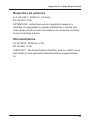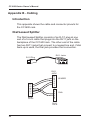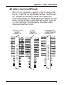
1
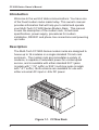
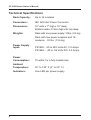
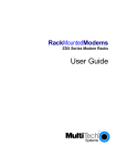
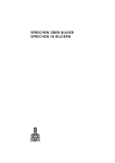
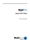
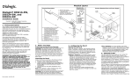
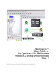
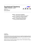
CC1600-Series
Card Cages
CC1600-Series
Modem Racks
Owner's Manual
Owner’s Manual
82047705 Revision F
CC1600-Series Modem Rack
This publication may not be reproduced, in whole or in part, without prior
expressed written permission from Multi-Tech Systems, Inc. All rights
reserved.
Copyright© 1998, by Multi-Tech Systems, Inc.
Multi-Tech Systems, Inc. makes no representations or warranties with
respect to the contents hereof and specifically disclaims any implied
warranties of merchantability or fitness for any particular purpose.
Furthermore, Multi-Tech Systems, Inc. reserves the right to revise this
publication and to make changes from time to time in the content hereof
without obligation of Multi-Tech Systems, Inc. to notify any person or
organization of such revisions or changes.
Record of Revisions
Revision
D
(11/18/96)
E
(10/13/97)
F
(4/13/98)
Description
Manual revised to include new power requirements and
clarification on 48V power leads.
Manual revised to include safety warnings and CE mark
information.
Manual revised. All pages at revision F.
Patents
This Product is covered by one or more of the following U.S. Patent
Numbers: 5.301.274; 5.309.562; 5.355.365; 5.355.653; 5.452.289;
5.453.986. Other Patents Pending.
TRADEMARKS
Multi-Tech and the Multi-Tech logo are trademarks of Multi-Tech
Systems, Inc.
Multi-Tech Systems, Inc.
2205 Woodale Drive
Mounds View, Minnesota 55112
(612) 785-3500 or (800) 328-9717
Fax (612) 785-9874
Technical Support (800) 972-2439
BBS (612) 785-3702 or (800) 392-2432
Internet Address: http://www.multitech.com
Fax-Back (612) 717-5888
Contents
Chapter 1 - Introduction and Description
Introduction ................................................................................ 6
Description ................................................................................. 6
Technical Specifications ............................................................. 8
Chapter 2 - Installation
Introduction .............................................................................. 10
Safety Warnings ....................................................................... 10
Safety Recommendations ........................................................ 11
Installation ................................................................................ 12
Power Supply Installation ......................................................... 16
Powering Up ............................................................................. 17
Chapter 3 - Service, Warranty
and Tech Support
Introduction .............................................................................. 20
Limited Warranty ...................................................................... 20
Tech Support ............................................................................ 21
Recording Rack Information .............................................. 21
Service ............................................................................... 22
The Multi-Tech BBS ................................................................. 23
To log on to the Multi-Tech BBS ......................................... 23
To Download a file .............................................................. 23
About the Internet ..................................................................... 25
About the Multi-Tech Fax-Back Service ................................... 25
Appendices
Appendix A - Safety Requirements........................................... 28
Appendix B - Cabling................................................................ 32
iii
iv
CC1600-Series
Card Cages
Chapter 1 - Introduction and Description
CC1600-Series Owner's Manual
Introduction
Welcome to the world of data communications. You have one
of the finest modem racks made today. This owner's manual
provides information that will help you to install and operate
your Multi-Tech CC1600-Series Modem Rack. This manual
covers the description of the modem rack, its technical
specifications, power supply, procedures for modem
installation, RS232C and phone line connections and powering
up mode.
Description
The Multi-Tech CC1600-Series modem racks are designed to
house up to 16 modems in a single standard 19-inch rack
enclosure. The modem rack accommodates a variety of
modems, is capable of redundant power for uninterrupted
service, and is available with either standard RJ11 jacks
(models with "-11L" suffix) or RJ21 multi-line jacks (models
with "-21" suffix). Both versions are available for use with
either universal AC input or -48v DC power.
1
0
1
0
Figure 1-1. CC16xx Rack
6
Chapter 1 - Introduction and Description
The CC1600 is a generic rack that accommodates a variety of
rackmount modems and DSUs. The CC1628 series is
designed specifically for V.34 modems. Both rack models
come in -11L and -21 versions. The -11L version connects to
standard RJ11 telephone phone cords. The -21 version has
three 50-pin connectors for dial-up and 2-wire or 4-wire leased
lines. Both models are equipped for universal AC input or
-48v DC. Finally, both models are available with either a
single power supply or dual (redundant ) power supplies for
uninterrupted power. A single power supply can maintain a full
complement of modems.
The CC1600-series rack makes it easy for you to monitor your
data communications. Each modem has its own set of LEDs,
with separate indicators for Receive Data, Transmit Data,
Carrier On, Speed, Off Hook, Data Terminal Ready, Ring
Indicator, and Error (Out-of-Service and Busy).
The rack measures 19" wide, 7" high, and 15" deep. The rack
is usually mounted in the same cabinet as your computer, or
can be enclosed in a separate cabinet of its own. Modems are
installed by simply opening the rack front door and sliding in
the modems. RS232C cables and phone cords are connected
to modem connectors at the back of the rack.
7
CC1600-Series Owner's Manual
Technical Specifications
Rack Capacity:
Up to 16 modems
Connectors:
IEC 320 Inlet Power Connector
Dimensions:
19" wide x 7" high x 15" deep
48.26cm wide x 17.8cm high x 38.1cm deep
Weights:
Rack with one power supply: 21lbs. (9.5 kg)
Rack with two power supplies and 16
modems: 30 lbs. (13.6 kg)
Power Supply
Input:
8
PS1600 - 90 to 245 Volts AC, 2.0 Amps
PS1648 - -40 to -56 Volts DC, 2.5 Amps
Power
Consumption:
70 watts, for a fully loaded rack
Ambient
Temperature:
32° to 120° F (0° to 50° C)
Indicators:
One LED per power supply
CC1600-Series
Card Cages
Chapter 2 - Installation
CC1600-Series Owner's Manual
Introduction
Multi-Tech rackmount modems are generally used in a central
site computer environment (i.e., connected to a mini or
mainframe computer) to automatically answer incoming calls
from remote users.
Command mode should be disabled unless you wish to give
the modem commands. Leaving command mode enabled
offers the possibility of a user calling into the modem and
reconfiguring it, or causing it to dial out. Refer to the
appropriate modem owner’s manual to configure the modem
for your application.
Safety Warnings
1. Never install telephone wiring during a lightning storm.
2. Never install telephone jacks in wet locations unless the
jack is specifically designed for wet locations.
3. Never touch uninsulated telephone wires or terminals
unless the telephone line has been disconnected at the
network interface.
4. Use caution when installing or modifying telephone lines.
5. Avoid using a telephone (other than a cordless type)
during an electrical storm. There may be a remote risk of
electrical shock from lightning.
6. Do not use the telephone to report a gas leak in the vicinity
of the leak.
10
Chapter 2 - Installation
Safety Recommendations
The following safety recommendations should be observed
when installing Multi-Tech CC1600-series modem racks.
•
Ensure proper installation of the CC1600-series modem
racks in a closed or multi-unit enclosure by following the
recommended installation as defined by the enclosure
manufacturer. Do not place the CC1600-series modem
rack directly on top of other equipment or place other
equipment directly on top of the CC1600-series rack.
•
If installing the CC1600-series modem rack in a closed or
multi-unit enclosure, ensure adequate airflow within the
rack so that the maximum recommended ambient
temperature is not exceeded.
•
Ensure that the CC1600-series modem rack is properly
connected to earth ground via a grounded power cord. In
the event that a power strip is used, ensure that the power
strip provides adequate grounding of the attached
equipment.
•
Ensure that the mains supply circuit is capable of handling
the load of the CC1600. Refer to the power label on the
equipment for load requirements.
•
Maximum recommended ambient temperature for the
CC1600 is 50° C (120° F).
•
This equipment should be installed only by properly
qualified service personnel.
•
Only connect like circuits. In other words, connect SELV
(Secondary Extra Low Voltage) circuits to SELV circuits
11
CC1600-Series Owner's Manual
and TN (Telecommunications Network) circuits to TN
circuits.
Installation
Perform the following procedure to install the CC1600-series
modem rack and install up to 16 modems in the rack.
1. Unpack the rack and check all items against the shipping
list to ensure that you have received the correct items.
Rack Components
A.
B.
C.
Rack
Power Cord
Owner's Manual
2. Inspect the rack for visible shipping damage. If damage is
observed, do not power-on the rack; contact Multi-Tech's
Technical Support for advice (refer to Chapter 3).
3. If no damage is observed, mount the rack in a standard
19-inch wide rack enclosure. Mounting hardware should
be provided with the rack enclosure.
4. If power supply is not installed in rack, refer to the
following section for power supply installation. If the power
supply is already installed, proceed to step 5.
5. Open the rack front door.
6. Unpack the modems to be installed in the rack.
7. Refer to the RackMounted Modem Owner's Manual for the
switch settings and parameters which pertain to your
application (dial-up/leased-line).
8. Slide a modem into one of the 16 available slots. The
component side of the card should be to the right as in
Figure 2-1. The modem's gold edge connector will mate
with the rack's backplane. The edge connector is offset
vertically so the modem cannot be inserted upside down.
12
Chapter 2 - Installation
Slot 1
Modem
Component
Side
Rack
Door
Figure 2-1. Modem Installation
9. Firmly seat the modem card into the backplane connector.
10. Repeat steps 7 through 9 for the remaining modems.
11. Connect an RS232C cable to the DB25 connector (25-pin
female connector) on the backplane of the rack. Start by
connecting the RS232C cable to the right-most channel
(slot 1) as viewed from the back of the rack.
Note: Any cables connected to the computer should be
shielded to reduce radio frequency interference. Keep
track of which computer channel belongs to which modem
in the rack. Most computer interface buses are grouped in
sixteens, which enables you to match modem and
computer channel numbers.
13
CC1600-Series Owner's Manual
Slot Number
DB25 Connector
(SELV Circuit)
16
13
1514
12
1110
7
9 8
6
3
54
2 1
RJ11 Connector
(TN Circuit)
Positive
Lead
Negative
Lead
48 Volt Power Supply
Figure 2-2. Cable Connections
12. If you are connecting your phone line directly to an RJ11
jack on the backplane of the rack, plug the telephone cord
into the RJ11 jack on the appropriate modem.
If you are connecting a -11L rack to leased lines or leased
lines with dial back-up, a Dial/Leased Splitter is required
between the leased line jack and the RJ11 jack on the
backpanel of the rack. The single RJ11 plug connects to
the RJ11 jackon the backpanel of the rack. The RJ11 jack
labeled Leased connects to the leased line connector. If
dial-back up is used, the RJ11 jack labeled dial should be
connected to the dial-back up line.
Note: The Dial/Leased Splitter is a custom part (a "Y"
cable) which includes an RJ11 plug that plugs into the
RJ11 jack on the backplane of the rack and is a 5-inchlong six-conductor cable terminated at two RJ11 jacks.
One jack is labeled Leased and the other Dial.
14
Chapter 2 - Installation
If you are connecting your phone lines (-21 series rack) to
the 50-pin connector on the backplane of the rack, plug
the appropriate phone cable into the appropriate 50-pin
connector (RJ21X). RJ21X connectors are TN circuits.
Note: Three 50-pin connectors are mounted on the back
of the -21 series rack backplane. The left 50-pin
connector (labeled Dial-Up/2-Wire Leased Line) is used to
connect all the modems in the -21 series rack to dial-up
phone lines. When 4-wire leased lines are being
connected, the two right 50-pin connectors (labeled 2-wire
Lease Line/4-wire Transmit Pair on the right and 4-wire
Receive Pair in the center) are used to connect the rack to
leased lines. When connecting to 2-wire leased lines, you
must first determine if your modem has dial back-up
capability. If it does, then use the right connector. If it
does not, then use the left (2-wire Lease Line) connector.
13. If an AC power source is being used, plug the AC power
cord supplied with the rack into the power cord connector
on the back of the rack and to a live AC outlet.
If a DC power source is being used, connect the negative
lead from the DC supply to the left terminal on the terminal
block on the back of the rack and the positive lead from
the DC supply to the right terminal on the rack.
15
CC1600-Series Owner's Manual
Power Supply Installation
The CC1600-series modem rack is configured with either a
single power supply or two (hot-swappable, redundant) power
supplies. A single power supply can maintain a full
complement of 16 modems or DSUs. To install a power
supply, perform the following procedure.
1. Unpack the power supply and check for visible shipping
damage. If damage is observed, do not install the power
supply; contact Multi-Tech's Technical Support for advice
(refer to Chapter 3).
Power Supply
Power Supply
Cover
1
0
Figure 2-3. Power Supply Installation
2. Using a Phillips screwdriver, loosen the two power supply
cover mounting screws and remove the cover from the slot
where you intend to install the power supply.
3. Slide the power supply into the two mating card guides
and firmly seat the power supply connectors into the
backplane connectors.
16
Chapter 2 - Installation
4. With a Phillips screwdriver, tighten the power supply
screws.
Warning: If only a single power supply is used, then the
unused opening should have a power supply cover in
place.
5. If a second power supply is being installed, repeat steps 1
through 4.
6. Return to the rack installation procedure to continue
installing the rack.
Powering Up
Once the power switch is turned on, the green LED on the
power supply(s) should be lit and the modems perform a
diagnostic self-test, indicated by the speed LEDs flashing in
sequence for approximately two seconds. If none of the
modems have power to them or the power supply LED(s) is
not lit, check the power cord connection and check that the AC
outlet is live. If one of the green power supply LEDs on the
front of the rack is not lit, then one of the redundant power
supplies may be defective or not installed correctly (i.e., not
making proper contact).
17
CC1600-Series Owner's Manual
18
CC1600-Series
Card Cages
Chapter 3 - Service, Warranty
and Tech Support
CC1600-Series Owner's Manual
Introduction
This chapter starts out with statements about your Multi-Tech
CC1600-series modem rack 2-year warranty. The next
section, Tech Support, should be read carefully if you have
questions or problems with your CC1600-series modem rack.
It includes the technical support telephone numbers, space for
recording your product information, and an explanation of how
to send in your CC1600-series modem rack should you require
service. The final three sections explain how to use our bulletin
board service (BBS), and get support through CompuServe
and the Internet.
Limited Warranty
Multi-Tech Systems, Inc. (“MTS”) warrants that its products
will be free from defects in material or workmanship for a
period of two years from the date of purchase, or if proof of
purchase is not provided, two years from date of shipment.
MTS MAKES NO OTHER WARRANTY, EXPRESSED OR
IMPLIED, AND ALL IMPLIED WARRANTIES OF
MERCHANTABILITY AND FITNESS FOR A PARTICULAR
PURPOSE ARE HEREBY DISCLAIMED. This warranty does
not apply to any products which have been damaged by
lightning storms, water, or power surges or which have been
neglected, altered, abused, used for a purpose other than the
one for which they were manufactured, repaired by the
customer or any party without MTS’s written authorization, or
used in any manner inconsistent with MTS’s instructions.
MTS’s entire obligation under this warranty shall be limited (at
MTS’s option) to repair or replacement of any products which
prove to be defective within the warranty period, or, at MTS’s
option, issuance of a refund of the purchase price. Defective
products must be returned by Customer to MTS’s factory
transportation prepaid.
20
Chapter 3 - Service, Warranty and Tech Support
MTS WILL NOT BE LIABLE FOR CONSEQUENTIAL
DAMAGES AND UNDER NO CIRCUMSTANCES WILL ITS
LIABILITY EXCEED THE PURCHASE PRICE FOR
DEFECTIVE PRODUCTS.
Tech Support
Multi-Tech has an excellent staff of technical support
personnel available to help you get the most out of your MultiTech product. If you have any questions about the operation
of this unit, call 1-800-972-2439. Please fill out the CC1600series modem rack information (below), and have it available
when you call. If your CC1600-series modem rack requires
service, the tech support specialist will guide you on how to
send in your CC1600-series modem rack (refer to the Service
section of this chapter).
Recording Rack Information
Please fill in the following information on your Multi-Tech
CC1600-series modem rack. This will help tech support in
answering your questions. (The same information is requested
on the Warranty Registration Card.)
Model No.:
Serial No.:
The model and serial numbers are on the bottom of your
CC1600-series modem rack.
Please note any diagnostic test results. Use the space below
to note rack status:
_________________________________________________________________________________
_________________________________________________________________________________
_______________________________________________________________________________
________________________________________________________________________________________________________
___________________________________________________________________________________________________________________
21
CC1600-Series Owner's Manual
Service
If your tech support specialist decides that service is required,
your rack may be sent (freight prepaid) to our factory. Return
shipping charges will be paid by Multi-Tech Systems.
Include the following with your rack:
•
a description of the problem.
•
return billing and return shipping addresses.
•
contact name and phone number.
•
check or purchase order number for payment if the
CC1600-series modem rack is out of warranty. (Check
with your technical support specialist for the standard
repair charge for your CC1600-series modem rack).
•
if possible, note the name of the technical support
specialist with whom you spoke.
If you need to inquire about the status of the returned product,
be prepared to provide the serial number of the product sent
(see Recording Rack Information on the previous page).
Send your rack to this address:
MULTI-TECH SYSTEMS, INC.
2205 WOODALE DRIVE
MOUNDS VIEW, MINNESOTA 55112
ATTN: SERVICE OR REPAIRS
You should also check with the supplier of your CC1600series modem rack on the availability of local service and/or
loaner units in your area.
22
Chapter 3 - Service, Warranty and Tech Support
The Multi-Tech BBS
For customers who do not have Internet access, Multi-Tech
maintains a bulletin board system (BBS) that mirrors its FTP
site. Information available from the BBS includes new product
information, product upgrade files, and problem-solving tips.
The phone number for the Multi-Tech BBS is (800) 392-2432
(USA and Canada) or (612) 785-3702 (international and local).
The BBS can be accessed by any asynchronous modem
operating at 1200 bps to 33,600 bps at a setting of 8 bits, no
parity, and 1 stop bit (8-N-1).
To log on to the Multi-Tech BBS
1. Set your communications program to 8-N-1.
2. Dial our BBS at (800) 392-2432 (USA and Canada) or
(612) 785-3702 (international and local).
3. At the prompts, type your first name, last name, and
password; then press ENTER. If you are a first time caller,
the BBS asks if your name is spelled correctly. If you
answer yes, a questionnaire appears. You must complete
the questionnaire to use the BBS on your first call.
4. Press ENTER until the Main Menu appears. From the
Main Menu you have access to two areas: the Files Menu
and News. For help on menu commands, type ?.
To Download a file
If you know the file name
1. From the Main Menu, type F to access the Files Menu,
then type D.
2. Enter the name of the file you wish to download from the
BBS.
3. If a password is required, enter the password.
4. Answer Y or N to the automatic logoff question.
23
CC1600-Series Owner's Manual
5. Select a file transfer protocol by typing the indicated letter,
such as Z for Zmodem (the recommended protocol).
6. If you select Zmodem, the transfer will begin automatically.
If you select another protocol, you may have to initiate the
transfer yourself. (In most datacomm programs, the PAGE
DOWN key initiates the download.)
7. When the download is complete, press ENTER to return to
the File Menu.
8. To exit the BBS, type G and press ENTER.
If you don’t know the file name
1. From the Main Menu, type F to access the Files Menu. For
a list of file areas, type L, press ENTER, then type L and
press ENTER again. (If you do not type the second L, you
will list all of the files on the BBS.)
2. Mark each file area you would like to examine by typing its
list number and pressing ENTER.
3. Enter L to list all the files in the selected file areas. Enter C
to go forward in the file list and P to go back.
4. To mark one or more files for download, type M, press
ENTER, type the list numbers of the files, and press
ENTER again.
5. Enter D. You will see a list of the files you have marked.
Enter E if you would like to edit the list; otherwise enter D
again to start the download process.
6. Select a file transfer protocol by typing the indicated letter,
such as Z for Zmodem (the recommended protocol).
7. If you select Zmodem, the file will transfer automatically. If
you select another protocol, you may have to initiate the
transfer yourself. (In most data communications programs,
the PAGE DOWN key initiates the download.)
8. When the download is complete, press ENTER to return to
the File Menu.
9. To exit the BBS, type G and press ENTER.
24
Chapter 3 - Service, Warranty and Tech Support
About the Internet
Multi-Tech is a commercial provider on the Internet. If you
prefer to receive service via the internet, you can contact Tech
Support via e-mail at the following address:
http://www.multitech.com/_forms/email_tech_support.htm
Multi-Tech's presence includes a Web site at:
http://www.multitech.com
and an ftp site at:
ftp://ftp.multitech.com
About the Multi-Tech Fax-Back Service
Multi-Tech’s fax-back system provides 24-hour access to
sales, marketing, and technical literature. Dial 612-717-5888,
follow the voice prompts, and request document number 10 for
a catalog of available documents. For convenence, have your
fax number handy: _________________________. From the
catalog of available documents, you can order newsletters,
white papers, press releases, etc. from the sales and
marketing index, or order basic modem operation and
troubleshooting guides from the technical support and
engineering index. Just enter the applicable FB Doc. # from
the left column of the catalog.
25
CC1600-Series Owner's Manual
26
CC1600-Series
Card Cages
Appendices
CC1600-Series Owner's Manual
Appendix A - Safety Requirements
1. No manual adjustments to the equipment are necessary
for connection to mains power within rated voltage and
frequency.
2. The power supply cord is intended to serve as the
disconnect device. The socket-outlet must be installed
near the equipment and be easily accessible.
3. To reduce the risk of shock, all openings should be
covered during normal operation of the equipment.
4. Use only plugs and cordage for connection of the power
supply to primary power which meets the safety and
regulatory requirements in the country of use.
5. Conductors must have a cross-sectional area of not less
than 1.00 mm2.
Exigences de sécurité
1. Aucun réglage manuel de l'équipement n'est nécessaire
pour des connexions à l'alimentation principale sous une
tension et une fréquence nominales.
2. Le cordon d'alimentation a été conçu pour servir de
dispositif de déconnexion. La prise d'alimentation doit être
installée près de l'équipement et doit être facile d'accès.
3. Afin de réduire les risques de choc, toutes les ouvertures
doivent être couvertes pendant le fonctionnement normal
de l'équipement.
4. N'utiliser que des prises et cordons d'alimentation
répondant aux normes de sécurité du pays de destination.
5. La superficie de la section des conducteurs doit être
supérieure ou égale à 1,00 mm2.
28
Appendix A - Safety Requirements
Requisitos de seguridad
1. No son necesarios ajustes manuales del equipo para la
conexión a la corriente de la red dentro del voltaje y
frecuencia establecidas.
2. El conector de alimentación de energía sirve como
dispositivo de desconexión. La toma de corriente se debe
instalar cerca del equipo y tener un acceso sencillo.
3. Para reducir el riesgo de sacudida eléctrica, todas las
aberturas deben estar cubiertas durante el manejo normal
del equipo.
4. Utilice solamente los enchufes y cables para la conexión
del suministro de energiá a la energiá primaria que
cumplan con los requerimientos regulativos y de
seguridad del país en que se usen.
5. Los conductores deben tener un área transversal mayor
de 1,00 mm2.
Sicherheitsanforderungen
1. Bei Anschluß am Versorgungsnetz innerhalb der
Nennleistung und -frequenz ist es nicht erforderlich,
dieses Gerät manuell nachzustellen.
2. Die Netzschnur dient als Trennvorrichtung. Die Steckdose
muß in der Nähe des Geräts installiert werden, um leicht
zugänglich zu sein.
3. Um Elektroschockgefahr zu vermindern, müssen beim
normalen Betrieb des Geräts alle Öffnungen abgedeckt
sein.
4. Zum Anschluß an das Primärstromnetz nur Stecker und
Anschlußkabeln benutzen, die den Sicherheits- und
Überwachungsvorschriften des Landes entsprechen, in
dem sie angewendet werden.
5. Leitungsdrähte müssen einen Durchmesser von
mindestens 1,00 mm2 haben.
29
CC1600-Series Owner's Manual
Mains Wiring Instructions (U.K.)
When wiring the mains plug, the following instructions must be
followed:
•
the core which is coloured green and yellow must be
connected to the terminal in the plug which is marked with
the letter E or by the earth symbol , or coloured green
and yellow.
•
the core which is coloured blue must be connected to the
terminal which is marked with the letter N or coloured
black.
•
the core which is coloured brown must be connected to
the terminal which is marked with the letter L or coloured
red.
Power Requirements
AC 90-245V, 50/60 Hz, 2.0A
DC 40-56V, 2.5A
CAUTION: Safety requirements are not fulfilled unless the
equipment is connected to a wall outlet socket that is provided
with an earth contact.
Alimentation Requise
C.A. 90-245 V, 50/60 Hz, 2.0A
DC 40-56V, 2.5A
ATTENTION: Les conditions de sécurité ne sont pas remplies
si votre équipement n'est pas branché sur une prise murale
avec mise à la terre.
30
Appendix A - Safety Requirements
Requisitos de potencia
C.A. 90-245 V, 50/60 Hz, 2.0 Amp
DC 40-56V, 2.5A
ATTENCION: Adviertase que los requisitos respecto a
medidas de seguridad no quedan satisfechos a menos que
este equipo eléctrico esté conectado a una toma de corriente
mural conectada a tierra.
Stromaufnahme
AC 90-245V, 50/60 Hz, 2.0A
DC 40-56V, 2.5A
VORSICHT: Die Sicherheitsvorschriften sind nur erfüllt, wenn
das Gerät an eine geerdete Wandsteckdose angeschlossen
ist.
31
CC1600-Series Owner's Manual
Appendix B - Cabling
Introduction
This appendix shows the cable and connector pinouts for
the CC1600 rack.
Dial/Leased Splitter
The Dial/Leased Splitter consists of an RJ11 plug at one
end of a 5-inch cable that plugs into the RJ11 jack on the
backplane of the CC1600 rack. The other end of the cable
has two RJ11 jacks that connect to a leased line and, if dial
back-up is used, the Dial jack provides that connection.
RJ11 Jacks
ED
L
AS
LE
IA
D
RJ11 Plug
RJ11
JACK
6
5
4
3
2
1
RJ11
PLUG
6
5
4
3
2
1
6
5
4
3
2
1
RJ11
JACK
32
LEASED
DIAL
Appendix A - Safety Requirements
-21 Series Connector Pinouts
Three 50-pin connectors are used on the -21 series rack;
they are located at the top of the backplane. The Dial-up/2Wire Leased connector is to the left (as viewed from
behind the chassis), the 4-wire Receive connector is in the
center, and the 2-Wire Leased/4-Wire Transmit connector
is on the right side of the backplane. Pinouts for each
connector are shown below.
RING2 27
J17
RING3 28
1
TIP 1
4W R RING1 26
2
TIP 2
4W R RING2 27
3
RING4 29
RING5 30
4
5
TIP 3
TIP 4
TIP 5
4W R
TIP1
2
4W R
TIP2
3
4W R
TIP3
4W X RING4 29
4
4W R
TIP4
4W R RING5 30
4W X RING5 30
5
4W R
TIP5
6
4W R
TIP6
4W X RING7 32
7
4W R
TIP7
4W X RING8 33
4W R RING3 28
4W R RING4 29
6
TIP 6
4W R RING6 31
RING7 32
7
TIP 7
4W R RING7 32
RING10 35
RING11 36
RING12 37
RING13 38
RING14 39
RING15 40
RING16 41
42
43
44
50 POSITION CONNECTOR
RING6 31
RING8 33
RING9 34
8
9
TIP 8
TIP 9
4W R RING8 33
4W R RING9 34
10 TIP 10
4W R RING10 35
11 TIP 11
4W R RING11
12 TIP 12
13 TIP 13
4W R RING12 37
36
4W R RING13 38
14 TIP 14
4W R RING14
15 TIP 15
4W R RING15 40
16 TIP 16
17
18
4W X RING1 26
1
J17
39
4W R RING16 41
42
43
50 POSITION CONNECTOR
RING1 26
TIP8
4W X RING9 34
9
4W R
TIP9
4W X RING10 35
10 4W R TIP10
4W X RING11
11 4W R TIP11
4W X RING12 37
12 4W R TIP12
4W X RING13 38
13 4W R TIP13
4W X RING14
14 4W R TIP14
4W X RING15 40
15 4W R TIP15
4W X RING16 41
16 4W R TIP16
17
18
19
44
45
46
47
20
21
22
46
21
47
48
22
23
48
23
50
25
49
50
19
24
25
J17
4W X RING6 31
4W R
20
24
4W X RING2 27
4W X RING3 28
8
45
49
2 WIRE LEASED /
4 WIRE TRANSMIT
CONNECTOR
4 WIRE
RECEIVE
CONNECTOR
36
39
42
43
44
50 POSITION CONNECTOR
DIAL UP / 2 WIRE
LEASED
CONNECTOR
1
4W X
TIP1
2
4W X
TIP2
3
4W X
TIP3
4
4W X
TIP4
5
4W X TIP5
6
4W X
TIP6
7
4W X
TIP7
8
4W X
TIP8
9
4W X
TIP9
10 4W X TIP10
11 4W X TIP11
12 4W X TIP12
13 4W X TIP13
14 4W X TIP14
15 4W X TIP15
16 4W X TIP16
17
18
19
45
20
46
21
47
22
48
23
49
24
50
25
33