1
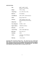
M3
Portable Audio Mixer
Operation Manual for Mixers with PCB V1.2
Copyright 2002
Professional Sound Corporation
Printed in the U.S.A.
TABLE OF CONTENTS
DESCRIPTION……………………………………………………………………………4
SAFETY WARNINGS……………………………………………………………………4
APPLICATIONS…………………………………………………………………………..4
FUNCTIONS
INPUTS……………………………………………………………………………5-6
A.
BALANCED INPUTS
B.
INPUT LEVELS
C.
MICROPHONE POWERING
D.
LOW CUT FILTER
E.
CHANNEL GAIN
F.
CHANNEL PANS
G.
BOOM POLE REMOTE CONTROL
OUTPUTS…………………………………………………………………………7-8
A.
BALANCED OUTPUTS
B.
MULTIPIN (BETA) CONNECTOR
C.
OUTPUT LIMITERS
D.
TRANSCRIPTION OUTPUTS
MONITOR………………………………………………………………………….8
A.
HEADPHONE MONITOR OUTPUT
TAPE RETURNS…………………………………………………………………..8
A.
TAPE RETURN GAIN
METERS…………………………………………………………………………….9
A.
PEAK READING METERS
2
B.
NIGHT (BACKLIGHT) USE
ADDITIONAL FEATURES…………………………………………………………10
A.
SLATE MICROPHONE
B.
REFERENCE OSCILATOR
C.
BATTERY TEST
D.
M-S AND X-Y STEREO RECORDING
POWERING………………………………………………………………………….11
A.
INTERNAL POWER, ALKYLINE BATTERIES
B.
EXTERNAL POWER
CONSTRUCTION……………………………………………………………………12
A.
CHASSIS
B.
ELECTRONIC TOPOLOGY
C.
ENVIRONMENTAL OPERATION
INTERFACING………………………………………………………………………13
A.
TO BETACAMS
B.
TO RDAT RECORDERS
C.
TO WIRELESS MICROPHONES
WARRANTY AND NON-WARRANTY SERVICE…………………………………14
SPECIFICATIONS…………………………………………………………………….15
3
DESCRIPTION
Thank you for purchasing the Professional Sound Corporation M3 Portable Audio
Mixer. PSC is confident that this new M3 Mixer has set new standards for
portable mixer technologies and features. Please feel free to contact us if you
have any comments or questions concerning your new mixer. Additionally, we
invite you to share your suggestions for new products you would like to see
developed.
Professional Sound Corporation extends a one-year warranty on parts and labor
to all M3 Mixer owners who return their warranty cards at the time of purchase.
This warranty gives you specific rights, which are stated on the card, and enables
us to keep you informed of product updates.
The PSC M3 Mixer provides all the functions necessary to produce studio quality
recordings in the field. It’s user friendly features, rugged design and sonic purity
make the M3 Mixer perfect for electronic news gathering (ENG) electronic field
production (EFP) and feature film production.
HEARING SAFETY WARNINGS:
Please be sure that you have read this entire manual before operating this
mixer.
While special attention has been given to your safety and hearing
protection, the operator determines proper and safe operating levels.
Please note the following:
Always turn down the headphone volume before plugging in your
headphones.
Always operate your headphones at the lowest practical level.
Be especially cautious in unknown or widely varying environments.
Remember, your ears are your livelihood. Turn it down!
APPLICATIONS
•
•
•
•
•
Electronic News Gathering
Location recording (Dialogue and Music)
Digital Recording and Playback
Broadcast remotes
Desktop Mixing for Video Post Production
4
INPUTS:
A.
BALANCED INPUTS
The PSC M3 Audio Mixer provides three input channels utilizing female XLR
connectors. The studio grade input circuitry is transformer balanced for improved
RF rejection and in-field practicality. The XLR connectors are wired as follows:
Pin 1 shield (ground), Pin 2 Audio high (in phase), Pin 3 Audio low (out of phase).
Balanced wiring enables longer cable runs without the worry of excessive noise
due to nearby electromagnetic and radio frequency interference. These
balanced inputs may be unbalanced if desired. Either pin 2 or 3 may be tied to
ground (pin 1) to unbalance the inputs of the M3 Mixer. Note: The AES standard
for unbalancing an XLR connector is to tie pin 3 to ground (pin 1).
B.
INPUT LEVELS
The PSC M3 Mixer can accommodate a wide range in input levels. Microphone
levels of all types can be handled as well as line level signals. The input range of
the M3 Mixer is –60dBu to +4dBu. Thus the M3 is compatible with all forms of
consumer and professional audio equipment. The input level switches are
located below and to the right of each input XLR connector. These input level
switches provide for three level settings: “D” Dynamic Microphone (0dB
attenuation), “C” Condenser Microphone (15dB attenuation), and “L” Line Level
(50dB attenuation) These input level attenuation settings are used to correctly
interface sources of varying levels to the M3’s preamplifiers. Correct level
matching ensures maximum headroom and lowest possible noise floor.
C.
MICROPHONE POWERING
The M3 Mixer can accommodate the most popular microphones used today.
The microphone powering switches are located directly below the input XLR
connectors. They can be switched to either Dynamic (D) or 48Phantom (48) or
12T (T).
In the Dynamic position the mixer provides no microphone powering. This
position is used with Dynamic Microphones, Line Level inputs and when using
Wireless Receivers.
In the 48 Phantom Position the mixer provides 48 volts DC to power 48PH
microphones or simplex powered microphones with a range of 9 to 52 volts or 12
to 52 volts. Pin 1 is shield to ground while pins 2 and 3 carry 48 volts DC. The
term “phantom” is derived from the fact that there is no voltage potential
developed across a dynamic microphone transducer that would interfere with its
operation. However, most portable wireless receivers will not operate with 48PH
turned on. We strongly recommend setting inputs to dynamic for use with all
wireless systems.
5
In the 12T powering position, the mixers provides 12 volts DC to pin 2 of the XLR
input. Pin 3 is referenced to ground and pin 1 is shield to ground. 12T powering
should only be used with microphones designed to operate for the “T’ standard
such as Sennheiser 416T and Scheops CMC4 Preamps.
D.
HI PASS FILTERS
Each input channel of the M3 Mixer is equipped with a high pass (low Cut) filter.
These filters are activated via the three way switches located below the adjacent
channel fader knobs. These filters will attenuate all frequencies below a preset
frequency at a rate of 6dB per octave. When set at “F”(Flat), frequencies below
20 Hz are effectively rolled off with the mixer operating at full frequency
response. Optional high pass filter settings of H and H2 will roll off the
frequencies below these figures at a rate of 6dB per octave (-3dB level at 100Hz
and 140Hz respectively. High pass filtering is important in location recording
where wind noise can cause pre-amplifier overload. This effect can be
minimized by switching the high pass filter setting to either a H or H2 cutoff. The
high pass filter switches are located on the front of the M3 Mixer.
E.
CHANNEL GAIN
In order to limit noise and increase headroom, the channel fader controls are
located in the feedback path of the pre-amplifiers. This provides continuously
variable gain rather than just a decrease in channel output level when an
overload situation occurs. This results in increased headroom and lower chance
of signal clipping (severe distortion).
F.
CHANNEL PANS
The new M3 Audio Mixer contains front panel mounted pan switches. These pan
switches are used to route the individual input channel’s signal to either the left or
right summing buss.
H.
BOOM POLE REMOTE CONTROL
The M3 Mixer offers the ability to remotely control the audio level of the channel
one input. This feature allows the operator to boom with two hands rather than
holding the boom pole with one and riding levels with the other. To use this
feature you must first set up the mixer as normal (microphone power turned on,
channel fader opened to a normal operating signal level, etc). Strap the boom
pole remote control to your boom pole, and plug the TA3F connector into the
“remote” control connector located on the left side of the mixer near the input
XLR’s. Set the slide fader on the remote control to it’s mid position and re-adjust
the channel fader upward (clockwise) until a normal signal level is indicated on
the meters. You are now free to ride gain using the remote control. Sliding the
knob toward the cable end of the remote control lowers the volume, sliding the
knob away from the cable end of the remote raises the volume. To remove the
boom pole remote control, you must simply press the release button of the TA3F
connector and pull on it. This unlocks the connector. *Safety Note* You must
6
always turn down the channel fader before removing the remote control!
High audio levels may occur if the channel fader is in the maximum or near
maximum setting when the boom pole remote control is unplugged. You
should note that the boom pole remote allows an approximate control range of 30
dB. This allows you complete working control over audio levels from the boom
pole.
OUTPUTS:
A.
BALANCED OUTPUTS
The M3 Mixer contains very high quality custom-made dual isolated output audio
transformers.
These transformers have been designed to provide wide
bandwidth, low distortion and real-world ease of use while feeding two Betacams
at the same time. One set of output windings feeds the standard XLR outputs
and the “Camera A” multi-pin connector. The second set of windings feeds the
“Camera B” multi-pin. Transformers have been chosen over a transformerless
design because of their inherent ability to interface with virtually any other device,
especially RF based products. This is very important in this day and age in
consideration of the frequent use of multiple RF receivers and transmitters.
These outputs are available via the right hand panel mounted male XLR
connectors. These outputs are switchable between line or microphone levels. At
the line level setting, the mixer outputs deliver a nominal 0dBv signal into 10K
Ohm loads. When set to microphone level, the outputs supply –50dBv signal
levels. Please note that 10K Ohm loads are typical of the loads imposed on the
mixer by most Betacams, and other recording devices. Additionally, the M3
Mixer’s outputs are capable of driving 600 Ohm loads.
B.
MULTI-PIN (BETACAM) CONNECTOR
The M3 Mixer is equipped with two multi-pin in/out connectors designed primarily
to interface with Betacams. These connectors provide the left and right balanced
outputs as normally found on the XLR output connectors as well as left and right
tape returns used for confidence monitoring. These multi-pin connections
provide a convenient means of interfacing to Betacams with only one connection.
In addition, this connection is located on the right hand side (outputs side) of the
mixer. By locating the connector on this side of the mixer, your Betasnake
cables can be conveniently routed from one side of the mixer providing a clean
and compact setup for use on the run.
C.
OUTPUT LIMITERS.
The limit threshold (activation level) is factory set at +3 on the meter. The limiters
compress the signal at approximately 2.7 to 1 ratio. This is to say an increase of
2.7dB in input signal will result in only a 1dB increase in output signal. Output
channel limiting is displayed on the LCD meter.
7
The M3 contains two separate limiters that are controlled by one front panel
mounted switch. This switch has three settings: Off, Separate (S), and Ganged
(G). In the off position, no limiting occurs.
In the separate position, the limiters act independently of each other. This is
especially useful when recording split tracks. I.E. interviewer and interviewee on
separate channels. Thus, if one person un-expectantly raises their voice, that
limiter will activate, but the other will not. In the ganged mode, both limiters are
tied together and can be triggered by either input. This is useful in recording
stereo as independent limiting would alter the stereo image.
PRACTICAL USE NOTE: IT IS HIGHLY RECOMMENDED THAT THE
LIMITERS BE USED AT ALL TIMES WHEN RECORDING TO BETACAM
TYPE CAMERAS.
Most video cameras have limited audio track headroom and can easily be
overloaded resulting in distortion of the recorded audio. Play it safe, use the
limiters!
D.
TRANSCRIPTION OUTPUTS
The M3 Mixer also contains two dedicated outputs used to feed transcription
recorders. These connectors are located directly below the main XLR outputs.
They are 3.5mm Stereo connectors wired as follows: Tip = Left, Ring is Right,
Sleeve = Ground. These connectors provide switch-able line level (-10dBv) or
microphone level (–50dBv) signal. This is compatible with most transcription
cassette recorders. The level setting switches are located on the bottom panel of
the M3 mixer.
E.
HEADPHONE OUTPUT
The Headphone output is located on the left side panel of the mixer. The M3
Mixer’s headphone amplifier circuitry is designed to drive virtually any headphone
with an impedance rating of 32 to 600 Ohms. The headphone circuitry is
controlled by the use of two switches and a volume control that are conviently
located on the front panel. The two switches are used to control what the
operator listens to. The most commonly used switch is located on the front panel
and is used to allow the operator to chose between monitoring right channel to
both ears ”R”, normal stereo “S”, left channel to both ears “S”’ Mono sum of left
and right signals “M” and well as pre-fader monitoring of channels 1,2 and 3 and
M-S decoding of MS stereo signals. The second switch is located on the upper
right corner of the front panel. This switch allow the user to monitor the tape
returns from up to two Betacam cameras.
*SAFETY NOTE* ALWAYS TURN DOWN THE HEADPHONE VOLUME
BEFORE PLUGGING IN YOUR HEADPHONES.
F.
TAPE RETURN
The M3 Mixer is equipped with two sets of tape returns used to monitor tape
confidence heads from most any recording device. These tape monitor
amplifiers can be adjusted to match the signal levels of most any device. These
8
levels are adjusted using a small jewelers screwdriver (or “Greenie” screwdriver).
The adjustment points are located on the bottom panel of the mixer. The
tape/direct switch is located on the upper right hand corner of the front panel.
When set to ”MIX” the phone amplifiers to monitor the mixers output signal. If
switched to “Camera A” (Tape), then the phone amplifies monitor the tape
returns from camera “A”. When set to “Camera B” the phone amplifiers monitor
Camera B.
METERS:
A.
PEAK READING METERS
The M3 Mixer is equipped with a custom made LCD meter. We designed this
meter to be easy to read and camera emulating. Because the most common use
of this type of mixer is with Betacams, we designed the M3’s meters to emulate
the peak reading attributes found on many Betacams. In this manor, you can be
confident of your recording levels even when the Betacam is being fed via
Betasnake cable or wireless transmission. The LCD meter also displays Left and
Right Limiter functions as well as Low Battery Warning. When the “Lo Bat”
indicator comes on, you have approximately 30 minutes of battery life remaining.
You should replace the batteries at your earliest convenience. This low battery
indicator can be set to sense the use of various battery types including AA
alkaline, and various voltage NP-1 rechargeable batteries.
The M3 Mixer is equipped with meter lamps used for night viewing of the meters.
The use of the meter back lighting adds approximately 80mA of power
consumption to the mixer. The continuos use of the meter lamps will shorten
your battery life by as much as 35%.
ADDITIONAL FEATURES:
A.
SLATE MICROPHONE
The M3 Mixer is equipped with a slate microphone. This microphone is activated
when the front panel “slate” momentary push button switch is pressed. The slate
microphone allows the operator to put voice slates (notes) on tape for later
reference. These are normally notes for editing tape. A level adjustment trim pot
is located on the bottom panel of the M3 Mixer. Turning the adjustment
clockwise will increase the slate microphone level. Turning the adjustment
counter-clockwise will lower the level. Audio from the three input channels is
automatically muted whenever the Slate microphone button is pressed. This
assures that the slates are clean and easily understood.
B.
REFERENCE OSCILLATOR
The M3 Mixer is equipped with a reference oscillator used for setting of levels
between the mixer and recorder. This known reference level is also used when
transferring tape during editing. The M3’s oscillator operates at 440Hz at “0” on
the meters. When setting up typical Betacams with LCD bar graph meters you
simply adjust the Betacams inputs until “0” is reached. From that point on, you
9
can monitor levels from the mixer only. We have chosen 440Hz simply because
it is much more pleasant in your headphones than the typical 1Khz used by other
manufactures. We have used 440 Hz on our mixers for many years. The
reference oscillator is equipped with a level adjustment trim pot located on the
bottom panel of the M3 Mixer. This adjustment is factory calibrated and should
not be adjusted without proper measurement equipment. It should be noted that
the three input channels are automatically muted whenever the Oscillator button
is pressed. The assures that the reference tone is of accurate level.
C.
BATTERY TEST
In addition to the low battery indicator on the LCD meter, the M3 Mixer is
equipped with a push button activated battery test function: When pressed the
remaining battery life is displayed on the top (left meter). A full battery will
indicate approximately “0” on the meter. A dead battery will not indicate on the
meter. You can read the meter as a “fuel gauge”. Full bar = full battery, half bar
= half battery, etc. This battery level meter can be adjusted for the differences in
battery types, NP-1 of various voltages or alkalines. This battery test function
can be adjusted to specific type batteries via a bottom panel mounted switches.
Because the M3 Mixer uses only a small amount of current, the mixer will
operate for many hours on even a “dead” NP-1 battery. Because the mixer will
operate down to 6.0Vdc, it will continue to operate long after the low battery
indication comes on when using NP-1 batteries. This can be useful in the field as
even a battery considered “dead” by the camera operator may work with your
M3. Note that over discharging of re-chargeable batteries on a regular basis is
not a recommended practice for everyday use!
D.
M-S AND X-Y STEREO RECORDING
The PSC M3 Mixer can be used to make stereo recordings in both the mid-side
and X-Y stereo techniques. The M3 Mixer is equipped with an input channel
ganging switch designed to allow the ganging of input channels 2 and 3. This
switch is located on the front panel of the mixer. When switched to the “ganged”
position, both input channels 2 and 3 are controlled by pot 3. All microphone
powering and attenuation settings remain independent. X-Y stereo recordings
are accomplished by plugging in two identical microphones into channels 2 and
3. The channel 2 pan switch is set to the left and the channel 3 pan switch is set
to the right. The headphone monitor mode switch is set to “stereo”.
If M-S stereo recordings are desired, the “M” or middle microphone (cardiod
pattern) is plugged into channel 2. The “S” or side microphone (Figure 8 pattern)
is plugged into channel 3. As with the X-Y setup, pan switch 2 is set to the left
and pan switch 3 to the right. In this case, the headphone mode switch is set to
“MS”. In the MS mode, the headphone amplifiers are fed MS decoded signals.
The left headphone amp is fed M-S signals and the right headphone is fed M+S
signals. In this manner, MS signals appear as standard stereo signals for
headphone monitoring purposes. Note that the MS decode function only affects
the headphone feeds, not the main XLR outputs.
10
More complete descriptions of the M-S and X-Y stereo recording techniques can
be found in the literature of the major microphone manufacturers such as
Neuman, Sennheiser, and Scheops.
POWERING:
A. INTERNAL POWER, ALKALINE BATTERIES
Six “AA” alkaline batteries can used to power the M3 Mixer. These batteries are
housed in a convenient battery compartment located on the right side of the
mixer. When using alkaline batteries, you can expect 3 to 7 hours of operation
under normal circumstances. Please not that the meter back lamps draw a great
deal of power and will shorten your battery life by as much as 35%.
Note: Never store your M3 Mixer for extended periods of time with alkaline
batteries installed in the mixer. There is a possibility that the batteries may
leak causing corrosion of the mixer. Battery leakage and the resulting
corrosion damage is not covered under the M3 Mixer warranty.
B. EXTERNAL POWER
The PSC M3 Mixer can also be externally powered from any source of DC power
from 7 to 18 Vdc. The mixer consumes approximately 200 mA over this voltage
range. This current consumption is nearly constant and does not vary
dramatically over operating voltages like other mixers. The external power
connector is located on the right side of the mixer. Pin outs of this Hirose 4 pin
connector are as follows:
Pin 4 (+) Positive
Pin 1 (-) Negative
Pin 2 and 3 switched contacts used with our NP-1 battery adapter.
This external DC input is protected from reverse polarity. If you in-advetantly
connect external power of the incorrect polarity, the mixer will not be damaged, it
simply will not power up.
CONSTRUCTION
A.
CHASSIS
The new M3 Mixer chassis has been designed for increased torsional rigidity.
This increased rigidity provides a stable base for the mixers modern electronics.
The complete chassis is formed from 0.040” and 0.050” aircraft aluminum. All
punching is done on a computer controlled “Strippet” rotary turret punch press for
extreme accuracy. In addition, through careful design, we have managed to
keep the overall weight of the M3 Mixer to under 4Lbs. (1.8Kg) total.
The mixers sheet metal is hand-formed using various press brake setups before
the all stainless steel threaded insert are pressed permanently into place. The
housing parts are then Chem Film TM plated for superior corrosion resistance
before being electro-statically coated with an epoxy powder coating. This
11
powder coat paint is then baked on in an oven. Powder coating chosen for its
durability and environmental friendly characteristics.
All silk-screening is printed sub-surface (below) a hardface lexan tm overlay.
This process provides a silk-screened label that is virtually wear proof. The
lettering will not wear off as on other mixers.
B.
ELECTRONIC TOPOLOGY
The new M3 audio mixer was designed from a clean sheet of paper. It utilizes
completely new circuitry designs based upon the latest advances in semi
conductor technology. In addition, it features surface mount technology for
reduced size and weight.
The M3 Mixer uses high quality transformers on its inputs and outputs.
Transformer topology was chosen for its inherent ability to reject RF, thus making
this new mixer perfect for use with multiple RF systems.
This new design uses modern semi-conductors from Maxim, Linear Technology
National Semiconductor and Burr-Brown to name but a few. These operational
amplifiers, voltage regulators and precision voltage references feature low power
consumption, low noise and low distortion. The also feature ability to swing from
rail to rail resulting in an energy efficient design.
C.
ENVIRONMENTAL OPERATION
Your new M3 Audio Mixer has been designed to operate under extreme field
conditions. The electronics have been designed to operate over a temperature
range of -4 to 158 degrees Fahrenheit (-20 to +70C) less the affects on batteries.
This in addition to the M3’s ability to operate under high humidity conditions
makes it perfect for harsh field conditions.
INTERFACING
A.
TO BETACAMS:
The PSC M3 Mixer is especially designed for easy interfacing with all popular
Betacam type cameras. The M3 is equipped with two 10 pin Hirose tm
connectors on the right-hand side panel. These all-inclusive connectors provides
both left and right balanced outputs and tape returns. Pin Outs are as follows:
Pin 1
Pin 2
Pin 3
Pin 4
Pin 5
Pin 6
Pin 7
Pin 8
Pin 9
Pin 10
Left Output High
Left Output Low
Right Output High
Right Output Low
Right Tape Return
Tape Ground
Left Tape Return
Tape Ground
Ground
Ground
12
The outputs of the “Camera A” multi-pin are electrically the same as the XLR
outputs on the right side of the mixer. Thus, the output levels can be switched to
the mic or live levels.
PSC manufactures a selection of standard M3 Beta snake cables for use with the
new M3 Mixer. These cables are available in standard and camera breakaway
versions from any authorized PSC dealer. Part numbers are as follows:
FPSC1091M3A
FPSC1091M3B
FPSC1091M3C
FPSC1091M3D
B:
15’ (4.5M)
15’ (4.5M)
25’ (7.5M)
25’ (7.5M)
Standard
Breakaway
Standard
Breakaway
TO RDAT RECORDERS:
The M3 Mixer can be interfaced to virtually any professional recorder via the
standard XLR outputs. In addition, you can use the 10 pin Hirose tm connectors
if you desire to use the tape return function.
C:
TO WIRELESS MICROPHONES:
The M3 Mixer will easily accept the output signal from virtually any wireless
receiver. It can accept microphone or line level signal via a simple switch setting.
Please note that most wireless receivers are not compatible with 48PH or 12T
mic power. You should always set the M4mkII’s mic powering switch to “D”
dynamic when using wireless receivers.
The M3 Mixer can also be used to send audio signals to Betacams via wireless
transmitters. The use of transmitters is normally accomplished by connecting the
M3’s output XLR to the audio input of the specific transmitter. Many transmitter
manufacturers supply application specific cables for this purpose. The M3 Mixer
has been designed to minimize RF interference through the use of output
transformers and other RF filtering. It is important to note that transmitter
placement greatly affects transmit range and clarity.
For best results,
transmitters should be mounted away from the mixers surface allowing unimpeaded RF radiation.
13
WARRANTY AND NON-WARRANTY SERVICE
In the unlikely event your M3 Mixer requires service it should be carefully packed
and shipped prepaid to:
Professional Sound Corporation
Service Department
28085 Smyth Drive
Valencia, CA 91355 USA
PH 661-295-9395
FAX 661-295-8398
e-mail [email protected]
Please call before shipping your mixer. We may be able to solve your problem
via the phone. Many older M4 and M4A+ and M4mkII Mixers have been
shipped in to us for service with incorrect switch settings. We are always willing
to help you with your M3 Mixer questions.
WARRANTY:
Complete details of the PSC M3 Mixer warranty are given on the enclosed blue
warranty registration card. If you did not receive one, please contact your local
dealer or call us directly.
14
SPECIFICATIONS
Size:
8.600” x 6.825” x 2.000”
(21.8cm x 17.3cm x 5cm)
Weight:
3.5Lbs. (1.6Kg)
Temp Range:
-4 to +158F (-20 to +70C)
Batteries:
6x AA Alkaline
Case Material:
0.040”, 0.050” Aircraft Aluminum
Finish:
Epoxy Powder Coat
Overlays:
0.005” Hardface Lexan tm with
Sub-surface Epoxy silk screening
Global Gain:
80dB
Freq. Response:
20-20Khz +/-1dB
Signal to Noise:
130dB EIN 150 Ohms
Distortion:
00.1% THD
Low Cut Filter:
100Hz, 140Hz 6dB/Octave
Mic Power:
DYN, 48 PH, 12T
Oscillator:
440Hz
Limiter:
1mS Attack, 100 mS Release
2.7:1 Ratio
Warranty:
1 Year, Limited
Copyright 2002, Professional Sound Corp. This manual and the complete M3
Mixer design is covered under various state, federal and international copyright
laws. No portion of this manual or any M3 mixer technologies may be reproduced
without the specific written permission of PSC. All rights reserved. This manual
and all M3 Mixer specifications subject to change without notice.
15