1
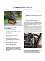
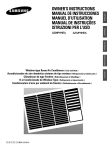
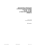
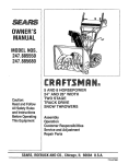
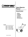
Service Manual
31AE5MLG729 Two-Stage Snow Thrower
NOTE: These materials are for use by trained technicians who are experienced in the service and repair of outdoor power
equipment of the kind described in this publication, and are not intended for use by untrained or inexperienced individuals.
These materials are intended to provide supplemental information to assist the trained technician. Untrained or inexperienced
individuals should seek the assistance of an experienced and trained professional. Read, understand, and follow all instructions
and common sense when working on power equipment. This includes the contents of the product’s Operators Manual, supplied
with the equipment. No liability can be accepted for any inaccuracies or omission in this publication, although care has been
taken to make it as complete and accurate as possible at the time of publication. However, due to the variety of outdoor power
equipment and continuing product changes that occur over time, updates will be made to these instructions from time to time.
Therefore, it may be necessary to obtain the latest materials before servicing or repairing a product. The company reserves the
right to make changes at any time to this publication without prior notice and without incurring an obligation to make such
changes to previously published versions. Instructions, photographs and illustrations used in this publication are for reference
use only and may not depict actual model and component parts. © Copyright 2005 MTD Products Inc. All Rights Reserved.
MTD Products LLC - Product Training and Education Department
FORM NUMBER 769-01418
9/2004
TABLE OF CONTENTS
General Information ....................................................................................................1
Tire Pressure .............................................................................................................2
Chute Installation ........................................................................................................2
Skid Shoe and Shave Plate Adjustment .................................................................... 2
Shave Plate Adjustment ............................................................................................. 3
Drive Control Cable Adjustment ................................................................................. 3
Auger Control Testing and Adjustment ...................................................................... 4
Shift Rod Adjustment ................................................................................................. 5
Auger Belt Replacement ............................................................................................ 5
Drive Belt Replacement ............................................................................................. 6
Friction Wheel Removal ............................................................................................. 6
Planetary Gear Removal ............................................................................................ 8
Drive Shaft Removal .................................................................................................. 9
Axlw Shaft Removal ................................................................................................. 10
Splitting the Unit ....................................................................................................... 11
FRiction Wheel Disc Disassembly ............................................................................ 13
Auger Pulley Removal .............................................................................................. 14
Auger and Impeller Removal .................................................................................... 14
Auger and Impeller Notes ......................................................................................... 15
Reducer Transmission ............................................................................................. 16
Reduction Transmission Disassembly ..................................................................... 16
Auger Idler Arm ........................................................................................................ 16
31AE5MLG729 Snow Thrower
GENERAL INFORMATION
31AE5MLG729
The Owner’s Manual packet includes and engine manual, extra shear pins and cotter pins as well as a packet
containing a sample of Sta-Bill fuel stabilizer that will
treat up to 2 ½ gallons of regular gas.
CAUTION: When assembling the handle for the
first time, use caution when lifting the handle.
The shift lever rod can get caught on the lower
handle cross member and if forced into position
can bend the spring shift lever. If necessary,
move the shift rod in front of the cross member
as you raise the handle into position.
There are two Supplement Sheets dated July 19 2004
and July 20, 2004 – Subject: Connector Sleeve on Two
Stage Snow Thrower shift rod. (Styles: E, F, H, K, L, N,
O, P and Q.)
Vibration may cause the rod connector sleeve to slide
up out of position. The remedy is to slide the connecter
sleeve fully down. Secure it in place by placing a rubber bushing over the top of the lower shift rod OR the
upper shift rod.. (A small piece of gas line can be used
as a bushing.) This will prevent the sleeve from sliding
up the shaft. See Figure 1.
YARD MACHINES SNOW THROWER
Model 31AE5MLG729
•
Serial Number 1G024B10168
•
Two Stage – 4 Cycle HMSK80-110 – 10.5 HP
•
28” Xtreme Auger
•
21” Intake Height
•
Tecumseh Engine With Electric Start
•
Power Steering
•
4 – Way Discharge Chute Control
•
6 Forward Speeds and 2 Reverse Speeds
•
Built in Halogen Light
•
Fully assembled with oil in engine
•
The 4-way discharge chute control: for quick and
easy snow directional changes.
•
Power Steering: For ultimate maneuverability
•
XTREME Auger: Break down of ice and snow
before pushing the pieces into the impeller.
•
Built-in Halogen Light: For use in early morning
or evening.
Rubber Bushing
Rod Connector Sleeve
Figure 1
Rubber bands hold the Auger and Drive control cables
in their respective nylon pulleys during shipping and
generally break during assembly of the handle.
Remove any pieces of rubber band after assembly.
1
There is a storage area in the handle panel used for
holding the spare auger shear pins. See Figure 2.
2.3.
Pull the hairpin clip out of the clevis pin on the
chute support rod. Save the hardware.
2.4.
Insert the round end of the chute control box on
the short tube of the chute assembly. See Figure
4.
Shear Pins Storage Area
Figure 2
1.
Chute Control
TIRE PRESSURE
Figure 4
Before operating, check tire pressure. Both tires should
be between 15 psi and 20 psi.
NOTE: If the tire pressure is not equal in both tires, the
unit may pull to one side or the other during operation.
2.
CHUTE INSTALLATION
2.1.
Apply a light lubricant to the rim/lip of the chute
base (and the underside of the chute assembly)
and position the chute over the base.
2.2.
Close the flange keepers to secure the chute to
the base. See Figure 3.
2.5.
Insert the other end of the chute control box into
the chute support tube.
2.6.
Insert the clevis pin, removed earlier, through the
holes on the chute control box and the chute
support rod. Secure with the hairpin clip. See
Figure 5.
Flange Keepers
Clevis Pin
Figure 5
3.
Figure 3
SKID SHOE AND SHAVE PLATE ADJUSTMENT
The space between the shave plate and the ground
can be adjusted.
NOTE: If the flange keepers will not easily click
into place, use the palm of your hand to apply
swift, firm pressure to the back of each.
For close snow removal on a smooth surface, raise
skid shoes higher on the auger housing to lower the
2
shave plate.
4.1.
Use a middle or lower position when the area to be
cleared is uneven, such as a gravel driveway.
Remove the carriage bolts and hex nuts, which
attach it to the snow thrower housing. See Figure 7.
CAUTION: Loose gravel can be picked up and
thrown by the auger, causing injury to the operator and bystanders and/or damage to the snow
thrower and surrounding property.
Carriage Bolts
For initial adjustment we recommend placing the shave
plate on a piece of cardboard.
3.1.
Loosen the four hex nuts (two on each side) and
carriage bolts attaching the skid shoes to the
auger housing. See Figure 6.
Hex Nuts
Figure 7
3.3.
Tighten the hex nuts.
NOTE: Make certain the entire bottom surface of
skid shoe is against the ground to avoid uneven
wear on the skid shoes.
4.
4.3.
Tighten nuts securely.
5.
DRIVE CONTROL CABLE ADJUSTMENT
Check the adjustment of the drive control as follows:
Figure 6
Move the skid shoes to the ground.
Install a new shave plate, making sure the heads
of the carriage bolts are to the inside of housing.
When the drive control is released and in the disengaged, or "up" position, the cable should have very little
slack. It should NOT be tight.
Skid Shoe
3.2.
4.2.
SHAVE PLATE REPLACEMENT
The shave plate will wear over time. It can be replaced
when worn excessively.
NOTE: You willl need to remove the skid shoes
prior to removing the shave plate.
5.1.
With the drive control released, push the snow
thrower gently forward. The unit should roll
freely.
5.2.
Engage the drive control and gently attempt to
push the snow thrower forward. The wheels
should not turn. The unit should not roll freely.
5.3.
With the drive control released, move the shift
lever back and forth between the R2 position
and the F6 position several times. There should
be no resistance in the shift lever.
If any of the above tests failed, the drive cable is in
need of adjustment.
3
5.4.
6.4.
Loosen the hex jam nut on the auger control
cable "Z" fitting and rotate the coupling end of
the cable downward to provide more slack or
upward to take up slack. See Figure 8.
To readjust the control cable, loosen the hex jam
nut on the auger control cable "Z" fitting. Rotate
the coupling end of the cable counterclockwise
to provide more slack. Retighten the hex jam
nut. See Figure 9.
Hex Jam Nut
Hex Jam Nut
Figure 8
Figure 9
5.5.
Retighten the hex jam nut and repeat all three
tests to verify proper adjustment has been
achieved.
6.
AUGER CONTROL TESTING AND ADJUSTMENT
6.1.
Start the engine and run it at full throttle.
6.2.
While standing in the operator position, engage
the auger. Do this several times.
6.3.
Release the auger control and walk to the front
of the unit. Confirm that the auger has completely stopped rotating and shows NO signs of
motion.
6.5.
Repeat Auger Control Test to verify proper
adjustment has been achieved.
WARNING: Never attempt to make any adjustments while the engine is running, except where
specified in operator's manual.
The augers are secured to the spiral shaft with four
shear pins and cotter pins. If the auger should strike a
foreign object or ice jam, the snow thrower is designed
so that the pins may shear. See Figure 10.
Shear Pins
IMPORTANT: If the auger shows ANY signs of
rotating, immediately return to the operator's
position and shut off the engine. Wait for ALL
moving parts to stop before re-adjusting the
auger control.
Figure 10
If the augers will not turn, check to see if the pins have
sheared.
One set of replacement shear pins has been provided
with the snow thrower.
4
When replacing pins, spray an oil lubricant into shaft
before inserting new pins.
7.
8.
AUGER BELT REPLACEMENT
8.1.
Using a 3/8” socket and extension, remove the
two self-tapping screws securing the plastic belt
cover to the frame. See Figure 13.
SHIFT ROD ADJUSTMENT
If the full range of speeds (forward and reverse) cannot
be achieved, adjust the shift rod.
7.1.
Place the shift lever in the fastest forward speed
position and remove the hairpin clip which
secures the ferrule to the shift lever. See Figure
11.
Hairpin Clip
Ferrule
Slf Tapping Screws
Figure 13
8.2.
Roll the auger belt off the engine pulley. See Figure 14.
Figure 11
7.2.
Auger Belt
Rotate the shift arm down as far as it will go. See
Figure 12.
Engine Pulley
Figure 14
NOTE: Place a scewdriver under the belt as you
pull slowly on the starter cord to wind the belt off
the pulley
Shift Arm
Figure 12
8.3.
Drain the gasoline from the snow thrower, or
place a piece of plastic under the gas cap.
7.3.
Thread the ferrule up or down the shift rod until it
aligns with the hole in the shift lever.
8.4.
Disconnect the spark plug wire from the spark
plug.
7.4.
Re-secure the ferrule with the hairpin clip
removed earlier.
8.5.
Carefully pivot the snow thrower up and forward
so that it rests on the auger housing.
5
8.6.
To remove and replace your snow thrower's drive belt,
proceed as follows:
Using a 3/8” socket, remove the four self-tapping
screws which secure the frame cover to the
frame. See Figure 15.
9.1.
Follow steps 8.1 through 8.6 in the AUGER
BELT REMOVAL Section. Then continue with
the following steps.
9.2.
Use a length of starter cord to pull the drive belt
idler pulley toward the right, away from the belt.
See Figure 17.
Starter Cord
Self Tapping Screws
Figure 15
8.7.
Wood Block
Using a piece of starter cord, unhook the support
bracket spring from the frame. See Figure 16.
Figure 17
Starter Cord
9.3.
Wedge a piece of wood under the pulley to hold
it in position.
9.4.
Roll the drive belt off engine pulley.
9.5.
Slip the drive belt off the pulley and between friction wheel and friction wheel disc. See Figure
18.
Support Bracket Spring
Friction Wheel Disc
Figure 16
Drive Belt
8.8.
Using a 9/16” socket and a ¾” wrench, loosen
and remove the shoulder screw which acts as a
belt keeper.
8.9.
Remove the belt from around the auger pulley,
and slip the belt between the support bracket
and the auger pulley
8.10. Reassemble auger belt by following instructions
in reverse order.
Figure 18
IMPORTANT: DO NOT forget to reinstall the
shoulder screw and reconnect the spring to the
frame after installing a replacement auger belt.
9.
9.6.
DRIVE BELT REPLACEMENT
6
Remove and replace belt in the reverse order.
10.
FRICTION WHEEL REMOVAL
10.7. Using a ½” socket remove the screws and bell
washers securing the wheels to the axles.
Remove both wheels. See Figure 20.
If the snow thrower fails to drive with the drive control
engaged, and performing the drive control cable
adjustment fails to correct the problem, the friction
wheel may need to be replaced.
10.1. Examine the friction wheel for signs of wear or
cracking and replace if necessary.
10.2. Place the shift lever in second reverse (R2) position.
10.3. Drain the gasoline from the snow thrower, or
place a piece of plastic under the gas cap.
10.4. Disconnect the spark plug wire from the spark
plug.
10.5. Carefully pivot the snow thrower up and forward
so that it rests on the auger housing.
10.6. Using a 3/8” socket, remove the four self-tapping
screws that secure the frame cover to the frame.
See Figure 19.
Figure 20
10.8. Using a 3/8” socket, remove the four screws
securing the right drive cover to the frame.
Remove the drive cover. Repeat for the left drive
cover. See Figure 21.
Self Tapping Screws
Screws
Right Drive Cover
Figure 19
Figure 21
7
If you're disassembling the friction wheel and replacing
only the rubber ring, proceed as follows:
10.9. Holding the friction wheel assembly, slide the
hex gear shaft to the right. See Figure 22.
10.13. Remove the four screws that secure the friction
wheel's side plates together. See Figure 24.
Drift Punch
Friction Wheel Assembly
Figure 22
NOTE: It may be necessary to use a drift punch
on the left side of the shaft to drive it from the
bearing.
Figure 24
10.10. Lift the chain off the small sprocket.
10.14. Remove the rubber ring from between the
plates.
10.11. Catch the bearing, sprocket and friction wheel as
they come off the shaft. See Figure 23.
10.15. Reassemble the side plates with a replacement
rubber ring.
IMPORTANT: Tighten each screw only one rotation before turning the wheel clockwise and proceeding with the next screw. Repeat this process
several times to ensure the plates are secured
with equal force.
10.16. Slide the friction wheel assembly back onto the
hex shaft and follow the steps above in reverse
order to reassemble components.
11.
PLANETARY GEAR REMOVAL
NOTE: It is not necessary to remove any belts to
service the planetary gears.
Hex Shaft
11.1. Remove the wheels on the side of the unit you
will be servicing.
Figure 23
NOTE: Maintain the correct order of parts during
disassembly.
10.12. Inspect the friction wheel for wear or damage.
NOTE: The friction wheel can be replaced as an
assembly or repaired.
If you're replacing the friction wheel assembly as a
whole, discard the worn assembly and slide the new
assembly onto the hex shaft. Follow the steps above in
reverse order to reassemble components.
8
11.2. Using a 3/8” socket, remove the shaft retainer
cover. See Figure 25.
11.6. Remove the planetary ring gear. See Figure 27.
Shaft Retainer Cover
Planetary Ring Gear
Figure 27
Figure 25
11.7. You can now remove and service the inner planetary gears.
11.3. Remove the ball bearing and flat washer.
11.4. Using snap ring pliers, remove the retaining ring.
See Figure 26.
NOTE: The procedure can be performed for
either planetary gear cluster.
12.
DRIVE SHAFT REMOVAL
NOTE: It is not necessary to remove any belts to
service the Drive shaft.
12.1. Remove both planetary gear clusters as covered
in REMOVAL OF THE PLANETARY GEAR section.
12.2. Lift up on the right side of the drive shaft to allow
removal of the right chain. See Figure 28.
Retaining Ring
Figure 26
Drive Shaft
11.5. Remove the three flat washer shims.
Figure 28
9
13.2. Remove both wheels.
12.3. Remove the right planetary gear cluster from the
drive shaft. See Figure 29.
13.3. Remove the frame cover.
13.4. Remove the spacers on each end of the axle.
See Figure 31.
Planetary Gear Cluster
Washer
Axle Spacer
Figure 29
12.4. Slide the drive shaft to the right while holding the
left planetary gear cluster in place. See Figure
30.
Figure 31
13.5. Remove both cotter pins from the clevis pins
securing the sprockets to the wheel axle. See
Figure 32.
Slide
Drive Shaft
Cotter Pins &
Clevis Pins
Figure 30
12.5. Remove the drive shaft and sprocket from the
unit.
Figure 32
12.6. Remove the drive chain from around the left
planetary gear cluster and remove the cluster
from the unit.
13.6. Remove the clevis pins from the axle.
NOTE: This is a split axle.
NOTE: During assembly, make sure the drive
clutch cable is routed on the inside of the drive
shaft.
13.
AXLE SHAFT REMOVAL
NOTE: It is not necessary to remove the drive
shaft in order to service the wheel axle.
13.1. Tip the unit up on the auger housing.
10
13.7. Slide the right axle to the right and remove the
gear, shim washer and hex flange bearing from
the axle as you remove it. See Figure 33.
NOTE: Assembly Tip. Independently assemble
both the right and left side axle components
through their respective frame sides, leaving the
axles flush with each gear. Slide the axle support tube between the gears and slide the axles
together. Line up the gears with the holes in the
axle and replace the clevis pins and cotter pins.
See Figure 35.
Right Axle
Axle Support Tube
Axle Support Tube
Figure 33
13.8. Slide the left axle to the left and remove the axle
support tube, gear, shim washer and hex flange
bearing as you remove it. See Figure 34.
Figure 35
Left Axle
14.
SPLITTING THE UNIT
Splitting the unit in two allows easy access to the friction disk and auger pulley.This is the preferred method
of servicing these parts.
14.1. Drain the gasoline from the snow thrower, or
place a piece of plastic under the gas cap.
14.2. Disconnect the spark plug wire from the spark
plug.
14.3. Remove the belt cover.
14.4. Remove the auger belt from around the engine
pulley.
Figure 34
11
14.8. Using a ½” socket, remove the TT screw, handle
tab and washer securing the support tube to the
frame. Remove the support tube from the unit.
See Figure 38.
14.5. Use needle nose pliers to remove the hairpin clip
from the clevis pin securing the 4-way chute
control assembly to the chute support tube.
Remove the clevis pin. See Figure 36.
Frame Screws
4-Way Chute Control
Support Tube
Hairpin Clip
Figure 38
Figure 36
14.9. Using a 3/8” socket, remove the AB screw
securing the auger cable guide bracket to the
frame. See Figure 39.
14.6. Remove the control assembly and set it on the
engine.
14.7. Using a ½” socket, remove the AB screw securing the lower portion of the chute support tube to
the frame. See Figure 37.
Auger Cable Bracket
AB screws
Figure 39
14.10. Using a ½” socket, remove the 4 bolts (2 on
each side) securing the auger housing assembly
to the wheel drive frame.
Figure 37
12
14.11. Separate the two halves of the unit. See Figure
40.
15.4. Using the engine pull start handle and a small
cotter pin removal tool, roll the drive belt off the
engine pulley. See Figure 42.
Drive Belt
Figure 40
Figure 42
NOTE: As you separate the housing halves,
remove the extension spring from the auger idler
bracket.
15.5. Using a 9/16” socket and screwdriver, remove
the Jam nut and bell washer securing the friction
wheel disc to the friction wheel support bracket.
See Figure 43.
CAUTION: After the unit is split, place wood
blocks at the rear of the wheel drive frame to
support it and keep it from tipping back.
15.
Hold screwdriver securely
while loosening jam nut
FRICTION WHEEL DISC DISASSEMBLY
15.1. Disconnect the spark plug wire from the spark
plug.
15.2. Split the unit. Refer to the SPLITTING THE UNIT
Section.
15.3. Using a piece of starter cord, pull the drive clutch
idler bracket away from the belt and block it with
a piece of wood. See Figure 41.
Figure 43
15.6. Slip the belt off of the disc and remove the disc
from the unit.
15.7. Assemble in reverse order.
Figure 41
13
16.4. Inspect the pulley and adapter for any wear or
damage.
NOTE: During reassembly note that there are
two mounting holes in the friciton wheel support
bracket. The friciton wheel disc must be installed
in the left hand hole as you face the friction
wheel support bracket. See Figure 44.
NOTE: During reassembly use Loctite 242 on
the screw.
NOTE: Torque to 160-200 inch pounds.
17.
Assemble in left mounting hole
AUGER AND IMPELLER REMOVAL
17.1. Remove the Auger Pulley as covered in the
AUGER PULLEY REMOVAL Section..
17.2. Using a ½” socket, remove the two flange lock
nuts securing the bearing housing to the auger
housing. Remove the bearing housing and bearing and inspect for wear or damage. See Figure
46.
Flange Lock Nuts
Figure 44
16.
AUGER PULLEY REMOVAL
16.1. Split the unit in two. Refer to the SPLITTING
THE UNIT Section.
16.2. Wedge a 2x4 between the spiral assembly and
the auger hosing to hold it in place. See Figure
45.
Figure 46
2x4
NOTE: The two carriage bolts used to secure
the bearing housing are held in place by push-on
nuts.
17.3. Lay the auger housing on its face.
Auger Pulley
Flat Washer
Screw
Figure 45
16.3. Using a 1/’2” socket, remove the screw and flat
washer securing the auger pulley to the impeller
assembly.
14
AUGER AND IMPELLER NOTES
17.4. Using a 1/2 “ socket, remove the four (two on
each side) hex screws securing the auger
assembly to the auger housing. See Figure 47.
•
The impeller worm shaft is machined to match a
double D machining in the impeller. See Figure
49.
Double “D” Machining
Hex Screws
Figure 47
Figure 49
17.5. Carefully tip back and remove the housing from
the auger assembly. See Figure 48.
•
Hex flange bearings are used at the ends of the
auger axle.
•
There a four shear pins used to attach the spiral
assemblies to the auger axle. Spare pins are
shipped with the unit.
•
Spiral assemblies are marked left and right for
proper installation. See Figure 50.
Figure 48
Spiral Assembly
Figure 50
NOTE: During assembly, place the auger housing face up when installing the auger and impeller assembly.
15
18.
19.2. Separate the housing halves using a putty knife.
See Figure 53.
REDUCER TRANSMISSION
18.1. The reducer can be serviced. It can also be purchased as an assembly.
19.3. Inspect all internal parts for wear or damage.
NOTE: On the top of the gearbox is inspection
and access hole for adding grease when and if
required. Remove the rubber grommet from the
lubrication port. See Figure 51.
Rubber Grommet
Ultra Gray
Figure 53
Reducer Transmission
NOTE: before assembly, clean off all of the ultragray sealant on both sides of the gearbox housing. Use ultra gray to reseal the housing before
assembly.
Figure 51
19.
20.
REDUCTION TRANSMISSION DISASSEMBLY
AUGER IDLER ARM
20.1. Split the unit. Refer to the SPLIT THE UNIT Section.
19.1. Using a 3/8” socket, remove the 5 TT screws
securing the reducer halves together. See Figure 52.
20.2. Remove the auger pulley. Refer to AUGER PULLEY REMOVAL Section.
5 TT Screws
Figure 52
16
20.3. Align one of the holes in the impeller with the
idler arm nut on the front of the auger housing.
See Figure 54.
Alignment Hole
Figure 54
20.4. Using a 9/16’ socket on a long extension and a
15/16” socket on a ½’ socket wrench, remove
the nut and shoulder screw attaching the idler to
the auger housing. See Figure 55.
Idler Arm
Figure 55
20.5. Inspect the idler pulley for wear or damage.
NOTE: The idler pulley can be removed using a
9/16” socket and a 9/16” opened end wrench.
17