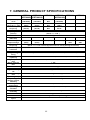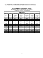
1
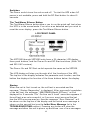
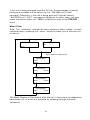
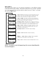
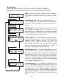
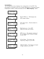
X R T Series
Uninterruptible Power Supply
User’s Manual
0
1
XRT Series User’s Manual
Table of Contents
1. INTRODUCTION
RECEIVING INSPECTION
SAFETY INSTRUCTIONS
2. SYSTEM DESCRIPTION
FEATURES
2
3
4
6
7
3. INSTALLATION
CAUTIONS
PROTECTION STRATEGIES
INSTALLATION PLACEMENT
INSTALLATION, STEP BY STEP
9
9
9
9
11
4. OPERATION
FRONT PANELS
ALARMS AND WARNINGS
WARNING EVENTS
OPTIONS
15
15
22
5. SYSTEM BATTERIES
STORAGE INSTRUCTIONS
BATTERY REPLACEMENT
6. TROUBLESHOOTING
TROUBLESHOOTING CHART
INITIAL ERROR MESSAGES
OPERATING FAULTS
SELF TEST
23
23
24
24
25
26
26
27
29
30
7. OBTAINING SERVICE
31
8. GENERAL PRODUCT SPECIFICATIONS
REMOTE COMMUNICATIONS
REMOTE DIRECT COMMUNICATIONS
BATTERY PACK AND RUN TIME SPEC’S
33
35
35
37
9. LIMITED PRODUCT WARRANTY
39
2
1. INTRODUCTION
Thank you for purchasing the Minuteman XRT series of Uninterruptible
Power Supplies. It has been designed and manufactured to provide many
years of trouble free service.
IMPORTANT!
Please read this manual before installing your UPS as it provides the
information to correctly set up your system for the maximum safety and
performance. Included is information on how the UPS functions to protect
your equipment from power line induced spikes, RFI and EMI, blackouts,
brownouts, sags and over-voltage conditions.
Included is information on customer support and factory service if it is
required. If you experience a problem with the UPS please refer to the
Troubleshooting guide in this manual to correct the problem or collect
enough information so that the Minuteman technical support department
can rapidly assist you.
Para Systems Life Support Policy
As a general policy, Para Systems Inc. does not recommend the use of any of its
products in life support applications where failure or malfunction of the Para Systems
product can be reasonably expected to cause failure of the life support device or to
significantly affect its safety or effectiveness. Para Systems does not recommend the
use of any of its products in direct patient care. Para Systems will not knowingly sell
its products for use in such applications unless it receives in writing assurances
satisfactory to Para Systems that (a) the risks of injury or damage have been
minimized, (b) the customer assumes all such risks, and (c) the liability of Para Systems
Inc. is adequately protected under the circumstances.
Examples of devices considered to be life support devices are neonatal oxygen
analyzers, nerve stimulators (whether used for anesthesia, pain relief, or other
purposes), auto transfusion devices, blood pumps, defibrillators, arrhythmia detectors
and alarms, pacemakers, hemodialysis systems, peritoneal dialysis systems, neonatal
ventilator incubators, ventilators for both adults and infants, anesthesia ventilators, and
infusion pumps as well as any other devices designated as “critical” by the United
States FDA.
Hospital grade wiring devices and leakage current may be ordered as options on many
Para Systems UPS systems. Para Systems does not claim that units with this
modification are certified or listed as Hospital Grade by Para Systems or any other
3
organization. Therefore, these units do not meet the requirements for use in direct
patient care.
4
RECEIVING INSPECTION
After removing your Minuteman XRT UPS from its carton, it should be inspected for
damage that may have occurred in shipping. Immediately notify the carrier and place of
purchase if any damage is found. Warranty claims for damage caused by the carrier
will not be honored.
PLEASE SAVE THE PACKING MATERIALS!
The packing materials that your UPS was shipped in are carefully designed to minimize
any shipping damage. In the unlikely case that the UPS needs to be returned to
Minuteman, please use the original packing material. Since Minuteman is not responsible
for shipping damage incurred when the system is returned, the original packing material
is inexpensive insurance.
Note: This equipment has been tested and found to comply with the limits for a Class A
digital device, pursuant to part 15 of the FCC rules. These limits are designed to provide
reasonable protection against harmful interference when the equipment is operated in a
commercial environment. This equipment generates, uses, and can radiate radio
frequency energy and, if not installed and used in accordance with the instruction
manual, may cause harmful interference to radio communications. Operation of this
equipment in a residential area is likely to cause harmful interference, in which case the
user will be required to correct the interference at his own expense.
This digital apparatus does not exceed the Class A limits for radio noise emissions from
digital apparatus set out in the Radio Interference Regulations of the Canadian
Department of Communications.
Le présent appareil numérique n’emit pas de bruits radioélectriques dépassant les
limites applicables aux appareils numérique de la Class A prescrites dans le Règlement
sur le brouillage radioélectrique édicte par le ministère dès Communications du Canada.
Shielded communications cables
must be used with this equipment
RADIO FREQUENCY INTERFERENCE
Warning: Changes or modifications to this unit not expressly approved by the party
responsible for compliance could void the users authority to operate this equipment.
5
IMPORTANT SAFETY INSTRUCTIONS
SAVE THESE INSTRUCTIONS
THIS MANUAL CONTAINS IMPORTANT
SAFETY INSTRUCTIONS;
Read this manual carefully before operating the UPS. All instructions and
warnings should be followed during installation, operation and
maintenance of the UPS.
CAUTION: RISK OF ELECTRICAL SHOCK. HAZARDOUS LIVE PARTS
INSIDE THIS POWER SUPPLY ARE ENERGIZED FROM THE
BATTERY SUPPLY EVEN WHEN THE INPUT AC POWER IS
DISCONNECTED.
CAUTION: A BATTERY CAN PRESENT A RISK OF ELECTRICAL
SHOCK, OR BURN FROM HIGH SHORT-CIRCUIT CURRENT.
OBSERVE PROPER PRECAUTIONS.
CAUTION: WHEN REPLACING BATTERIES USE THE SAME NUMBER
AND TYPE OF SEALED LEAD-ACID BATTERIES.
CAUTION: PROPER DISPOSAL OF BATTERIES IS REQUIRED.
REFER TO YOUR LOCAL CODES FOR DISPOSAL REQUIREMENTS.
CAUTION: AVOID INSTALLING THE UNINTERRUPTIBLE POWER
SUPPLY (UPS) IN LOCATIONS WHERE THERE IS WATER OR
EXCESSIVE HUMIDITY.
CAUTION: CONNECT THE UNINTERRUPTIBLE POWER SUPPLY TO A
TWO POLE, THREE WIRE GROUNDING MAINS RECEPTACLE. THE
RECEPTACLE MUST BE CONNECTED TO APPROPRIATE BRANCH
PROTECTION (FUSE OR CIRCUIT BREAKER). CONNECTION TO ANY
OTHER TYPE OF RECEPTACLE MAY RESULT IN A SHOCK HAZARD
AND MAY VIOLATE LOCAL ELECTRICAL CODES.
CAUTION: DO NOT ALLOW WATER OR ANY FOREIGN OBJECT TO
GET INSIDE THE UNINTERRUPTIBLE POWER SUPPLY. DO NOT PUT
OBJECTS CONTAINING LIQUIDS ON OR NEAR THE UNIT.
6
INSTRUCTIONS IMPORTANTES
CONCERNANT LA SÉCURITÉ
CONSERVER CES INSTRUCTIONS.
CETTE NOTICE CONTIENT DES INSTRUCTIONS
IMPORTANTES CONCERNANT LA SÉCURITÉ.
ATTENTION: RISQUE DE CHOC ÉLECTRONIQUE. CE BLOC
D’ALIMENTATION COMPORTE DES PIECES SOUS TENSION
DANGEREUSE ALIMENTÉES PAR LES PILES MEME LORSQU’IL EST
DÉBRANCHÉ DU SECTEUR.
ATTENTION: UNE BATTERIE PEUT PRÉSENTER UN RISQUE DE
CHOC ÉLECTRIQUE, OU DE BRULURE PAR TRANSFERT
D’ENERGIE. SUIVRE LES PRÉCAUTIONS QUI S’IMPOSENT.
ATTENTION: POUR LE REMPLACEMENT, UTILISER L E M E M E
NOMBRE DE BATTERIES DU MODÉLE LEAD-ACID SCELLÉES.
ATTENTION: L’EMINATION DES BATTERIES EST RÈGLEMENTÉE.
CONSULTER LES CODES LOCAUX À CET EFFET.
ATTENTION: LA SORCE D’ALIMENTATION PERMANENTE (UPS)
DANS UNE PRISE DE COURANT À 3 DÉRIVATIONS (DEUX POLES ET
LA TERRE). CETTE PRISE DOIT ÊTRE MUNIE D’UNE PROTECTION
ADÉQUATE (FUSIBLE OU COUPE-CIRCUIT). LE BRANCHEMENT
DANS TOUT AUTRE GENRE DE PRISE POURRÎT ENTRAÎNER UN
RISQUE D’ÉLECTROCUTION ET PEUT CONSTITUER UNE
INFRACTION À LA RÉGLEMENTATION LOCALE CONCERNANT LES
INSTALLATIONS ÉLECTRIQUES.
ATTENTION: NE PAS INSTALLER LA SOURCE D’ALIMENTATION
PERMANENTE (UPS) DANS UN ENDROIT OÙ IL Y A DE L’EAU OU
UNE HUMIDITÉ EXCESSIVE.
ATTENTION: NE PAS LAISSER DE L’EAU OU TOUT OBJET
PÉNÉTRER DANS LA SOURCE D’ALIMENTATION PERMANENTE
(UPS). NE PAS PLACER DE RÉCIPIENTS CONTENANT UN LIQUIDE
SUR CET APPAREIL, NI À PROXIMITÉ DE CELUI-CI.
7
2. SYSTEM DESCRIPTION
The XRT series of Uninterruptible power supplies are based on an
advanced true sinewave power system that filters and protects the
electronic equipment from all types of power line problems. The various
models provide from 600 VA to 2000 VA of power for voltage ranges of
120 VAC, 208 VAC and 240 VAC single phase 60 Hz. units, and 220
VAC through 240 VAC 50 Hz. units. At all power levels and voltage
ranges the load is protected against AC line spikes, surges, dropouts,
brownouts and blackouts. All 60 Hertz models include electrical isolation
from the power line to the AC load. During operation, all of the critical
parameters are continuously monitored. The parameters may be
monitored at the UPS with an LED display on the XRT600, or with a
sophisticated LCD display that contains 32 characters on the XRT1000
and larger units. In all models the communications port can be used with
the Minuteman Sentry or PowerMon software to report all of the critical
parameters as well as controlling the UPS’s functions via remote control.
Built in is the provision for a remote master Output Power OFF switch so
that a user-supplied power down switch or relay can immediately shut off
the output power.
The XRT series of UPS’s are “Line-Interactive”. That is, during normal
operation from the AC line, the line AC is passed through an isolation
transformer* and filtering system that provides the maximum efficiency,
safety and reliability. During normal AC operation, the incoming line
voltage is continuously monitored and automatic correction is made for
under-voltage or over-voltage conditions. This provides AC line correction
for a range of 75% to 116% of the nominal line voltage. When these
limits are exceeded, or if the line frequency varies more than plus or
minus 3 Hertz, the unit automatically switches to battery power until
normal AC is restored. In normal operation the battery is continuously
charged so that full battery power is always available.
*
Isolation transformer is on the 60 Hz. units only.
8
FEATURES
Extended Battery Run Time
All models of the XRT series may add multiple optional external XRTBP
battery packs to extend the time that the units can provide power. UPS
de-rating is not required for the additional battery packs. The XRT600
model contains an internal battery, whereas the higher power models
require at least one XRTBP battery pack.
RFI/EMI Suppression
The design features, not only the standard input line filtering, but
contains a specially manufactured transformer* that shields the output
from line and inverter spikes resulting from capacitive coupling between
windings. This double protection insures that interference and spikes
cannot get to your equipment, and conversely your equipment cannot
transmit spikes to other equipment on the power line.
No Power Factor De-rating
The XRT series of UPS’s automatically support power factors in the
range of 0.6 to 1.0. This means that no de-rating is required for high
power factors since the unit is capable of supplying full rated power
(instantaneous watts) in either the ON-LINE or On-Battery conditions.
Enhanced Battery Management
To maintain the service life of the battery, the XRT provides various
features. During normal on-line functions the XRT continuously monitors
the battery voltage and keeps the battery at full charge via an intelligent
battery charger built into the unit. The battery’s condition is monitored at
all times, and if a low battery condition is detected, the condition is
reported to the front panel and to the serial communications port. If a low
battery condition is detected, the unit will continue to function on the AC
line. While the unit is on-line, the external battery pack(s) may be
replaced without disruption to the output power. In the XRT1000,
XRT1500 and XRT2000 units, the battery charge condition is reported by
the battery voltage on the LCD display screen, whereas in the XRT600
unit the battery charge condition is reported by LED’s on the front panel.
Remote Communication and Control
Built into the XRT series is a Minuteman standard RS-232
communications port. With the Minuteman Power Management software,
2-way communications can be maintained with a remote computer. All
pertinent data about the UPS can be transmitted to the computer, and
9
commands from the computer can control the UPS. The interface also
allows a single switch to control the output power from the UPS so that a
user-supplied Output Power Off switch or relay can immediately remove
power from the load, or restore power once the problem has been
corrected. See Remote Communications chapter for details of the
communications port.
Built in Self Test
To insure the functionality of the UPS, there are four built-in self tests.
The first is when the unit is switched on, a self test is run to insure the
operation of the backup mode, the condition of the battery and the
inverter circuit. This test takes about 10 seconds. Pressing the Test
button, or selecting the Quick Test command from the LCD menu will run
the built-in self test, verifying the operation of the UPS. The third test
mode runs a self test every 14 days to insure the UPS is always ready to
respond to a power problem. The fourth test is the Test to Low Battery
Warning and verifies the condition of the battery system by switching to
inverter power until the battery reaches the Low Battery Warning
condition and then switching back to the ON-LINE mode. During the
“Test to Low Battery”, you may monitor all of the status values and
terminate the test at any time.
The XRT1000 through XRT2000 units have a 32 character LCD display,
three push buttons, and the Power On and DC Start switches.
The Power and DC Start switch operate the same as the XRT600.
The LCD display will step you through all of the functions of the UPS.
The top line of the display indicates the parameter and function, and the
bottom line displays the function of the three buttons below the display.
10
3. INSTALLATION
CAUTION: Do not connect a laser printer to the UPS along with other
computer equipment unless the UPS is rated at 2000 VA or higher. A
laser printer periodically draws significantly more power than when idle,
and may overload the UPS. Verify that the UPS can support the loads
when the printer is in full operation (printing).
PROTECTION STRATEGIES
Minuteman UPS’s provide high quality protection from AC input power
line disturbances to your equipment. However, there are other potential
entry points for damaging surges in information systems. These include
serial ports (RS232, RS422, RS485, etc.), parallel ports (especially
printers not connected to the UPS), telephone lines and network
connections. These other entries must be considered in developing a
comprehensive system protection strategy. Contact your dealer or
Minuteman for information on a complete set of related products
designed to accomplish total system protection. There are some
guidelines listed below that will help in your installation, whether or not
secondary protection is available.
Verify that all electrical outlets are properly grounded.
Do not connect the UPS and protected equipment to the same electrical
service branch that heavy motor loads like air conditioners, copiers,
refrigerators, and heavy electrical machinery are on. Plug all power
protection and protected equipment into the same branch where
possible.
Follow the next steps to install your UPS.
INSTALLATION PLACEMENT
Select the location of the UPS and optional battery pack(s) with care and
use the following precautions:
Select a location that provides unrestricted air flow. It is important to
leave at least 2 inches of space between any object and the sides of the
UPS.
11
Do not place anything on the top of the UPS.
Avoid locations near heating devices.
Avoid locations near water or excessive humidity.
Do not expose the UPS to direct sunlight.
Route power cords where they cannot be walked on or
damaged, or surrounded by other power cords or
communication cables.
Use common sense about placing the UPS where it
cannot be accidentally bumped or turned over.
The battery packs and UPS unit must be placed on a level, smooth
surface and cannot be stacked more than 4 units high. The UPS unit
must be the topmost unit. A multiple battery pack suggested layout is
shown below:
Remember to leave at least 2 inches of clearance
around the UPS unit for air flow.
12
INSTALLATION, STEP BY STEP
1. Insure UPS Power switch is OFF. Place the optional XRTBP
battery pack(s), if used, and XRT UPS in its final location.
2. When installing the XRT1000 and above UPS’s or the XRT600
with optional battery pack(s):
a) Remove the self stick protective strip from the rear of the XRT600
(not required on XRT1000 , 1500, and 2000), and from the optional
battery pack cable.
b) Loosen the retainer screws on the rear of the UPS and drop the
retainer bracket down.
c) Plug the battery pack cable connector into the XRT remote battery
pack connector insuring connections mate RED to RED and
BLACK to BLACK. Push the retaining bracket “up” to secure the
battery connector in place and re-tighten the screws.
d) Verify the bracket will not allow removal of the connector.
Each
battery pack is “daisy chained” in a similar fashion with the cable
from the last battery pack connected to the previous pack. Remove
the protective strips only from the battery connectors that are
used.
NOTE: When the protective strip is removed from the XRT UPS or the
XRTBP cable connector, battery system voltage (48 VDC) is
present at these connector contacts. Please keep the connector
contacts covered with the protective strip when not mated with
another connector.
Battery Pack Connection Diagram
13
3. If you have additional Transient Voltage Surge Suppression (TVSS)
devices in your system, they may be connected to the Earth Ground lug
at the rear of the UPS. This provides a single point connection to
minimize the potential of surges to disrupt the system. This lug is
connected to the SAFETY GROUND lead in the AC input power cable.
4. Plug in the UPS to the utility power outlet.
XRT600, XRT1000, XRT1500 and XRT2000 Back panels
NOTE: Due to various input and output options available, your unit
may not be pictured exactly.
The XRT600, XRT600/2, XRT1000, XRT1000/2 and XRT2000/2 are fitted
with an IEC 320 input power connector. The remaining units have a preinstalled power cord to match their input power requirements and
voltages. The IEC 320 connector is the familiar computer input power
connector. XRT600 and XRT1000 units sold in the United States come
with an input power cable with a standard 5-15 male plug on one end and
an IEC 320 female plug on the other. Plug the IEC 320 connector into the
UPS and the male plug into a standard wall socket. Power cords for all
international models must be ordered separately if required.
5, If used, plug your remote communications line, into the DB-9
communications port connector. Your UPS will function correctly without
using the port.
6. Turn the Power switch to the “on” position. With commercial power
present and in the correct voltage and frequency range, the UPS will
14
automatically run a self test and at the successful completion, provide
power to the output receptacles and indicate “normal AC”. Certain faults
will prevent the UPS from supplying power to your equipment and will
cause an error status to be displayed and an audible alarm to sound. If
this occurs see the TROUBLESHOOTING section. To insure the
batteries are completely charged, it is a good idea to leave the UPS on
for 8 hours before using it to run your system. We understand that in
most cases you may not have the luxury of waiting for the batteries to
become fully charged, therefore you may install your equipment and
begin using the UPS immediately. If a power failure occurs before the
batteries are fully charged, the UPS may not supply power for the length
of time you would normally expect in battery backup mode.
7. Plug all equipment to be protected into the UPS output receptacles.
Insure that you do not exceed the maximum output power
capability of the XRT UPS (refer to UPS back panel or
electrical specifications in this manual).
Turn on your protected equipment one unit at a time and
verify that the “100% Load” condition is not exceeded.
Depending on the XRT model, the Load condition will be
displayed on the front panel as follows:
a) The XRT600 will provide an indication of the UPS status on the
LED front panel.
XRT600 Front Panel Showing Load LED’s
b) The XRT1000 and above will display the UPS status on the LCD
screen.
15
Front Panel Load Menu on LCD Screen
If an alarm condition exists, the condition will be reported on the front
panel. If no AC Power is present and the battery is charged, pressing the
DC START switch for approximately 5 seconds will bring up the UPS in
the inverter mode and provide power to the protected equipment from the
battery.
16
4. OPERATION
FRONT PANELS
The operation of the UPS depends on which front panel is used. The
following section explains the operation for the LED and the LCD front
panels.
LED Front Panel
The top four LED’s (Green) provide 3 functions.
• During normal AC operation: The top LED’s indicate a measure of
load.
• During battery mode: The top LED’s indicate the battery charge
condition which indicates approximate battery power remaining.
• During a fault condition: The top LED’s display an error code.
The second (bottom) row of LED’s provide status information.
• AC normal LED: Glows green when normal AC is available to the
unit.
• Regulator LED: Glows yellow when AC is present but outside normal
range.
• On battery LED: Glows red when the unit is supplying power from
the batteries (Inverter on).
• Low battery LED: Glows red when the batteries are weak and need
charging or replacement.
• All LED’s off: This indicates the unit is turned off or an error condition
has occurred. If an error has occurred, the internal alarm will sound
and an error code will be displayed on the upper four LED’s. Refer to
the TROUBLESHOOTING section for a description of the error code
and the appropriate action to take.
17
Switches
The Power switch turns the unit on and off. To start the UPS when AC
power is not available, press and hold the DC Start button for about 5
seconds.
The Test/Alarm Silence Button
The Test/Alarm Silence button allows you to run the quick self test when
the UPS is in the normal mode. If an error was detected and you wish to
reset the error display, press the Test/Alarm Silence button.
LCD FRONT PANEL
The XRT1000 through XRT2000 units have a 32 character LCD display,
three push buttons, and the Power On and DC Start switches. (Both 120
and 220 VAC versions)
The Power On and DC Start switch operate the same as the XRT600.
The LCD display will step you through all of the functions of the UPS.
The top line of the display indicates the parameter and function, and the
bottom line displays the function of the three buttons below the display.
Startup
When the unit is first turned on, the self test is executed and the
message “Startup Diagnostics” is displayed. After successful completion
of the self test, the message “MINUTEMAN Model XRTxxxx” will be
displayed for 5 seconds. The “On-Line xxx% Load” menu then appears. If
the self test was not successful, or if an error event occurred the last
time the UPS was powered on, then the message “Error Detected” will
be shown on the top line of the display and the actual error message is
shown on the second line (see the Initial Error Message list in the
TROUBLESHOOTING section). Pressing any button will clear the
message and allow the unit to power up and show one of two messages.
18
If the unit is being powered from the AC line, the percentage of actual
load power available will be shown by the “ON-LINE xxx% Load”
message. Otherwise, if the unit is being powered from the battery,
“BACKUP xx.xV BAT” message is displayed. In either case, you may
press the button under the “MENU” selection to step to the STATUS
menu.
Menu Flow
Note: The “road-map” through the menu system is shown below. In each
individual menu, pressing the “menu” button will take you to the next set
of menus.
ONLINE 50% Load
BACKUP 52.3V
Bat
Menu
Menu Selection Sequence
Status Menu
Menu
Scroll
Test Menu
Menu
Scroll
Setup Menu
Menu
Scroll
Config Menu
Menu
Scroll
The Mode Display will be shown after the unit’s first power up diagnostics
have been run, or when it is selected by stepping through the menu
selections.
19
Status Menu
The status menu allows you to read the parameters of the UPS according
to the flowchart shown below. The button under the word “Scroll” will step
you to the next selection and the button under the word “Menu” will step
you to the TEST menu.
Load
50%
Menu
Scroll
Load
750VA
Menu
Scroll
AC Input 120.0V
Menu
Scroll
Input 60Hz
Menu
Scroll
Load xxx% : Percentage of load compared to power
rating of the unit. If the load shows greater than 100
percent, then the load is too high for the UPS.
Load xxxVA : VA load currently being supplied by
the UPS. If the load exceeds the VA rating of the unit
then the load is too high for the UPS.
AC Input xxx.xV : Indicates the incoming AC Volts. If
the voltage is out of range for your UPS then you have
the wrong model type or your commercial power is
Input xx HZ : Indicates incoming frequency. If the
frequency is out of the acceptable range, then you
have bad incoming power.
AC
Output120.0V
AC Output xxx.xV : Indicates output voltage.
Output 60Hz
Output xx HZ : Indicates output frequency.
Menu
Scroll
Battery 50.2V
Menu
Scroll
Temp 30.1C
Menu
Battery
xx.xV : Battery voltage. The acceptable
values are in the range of 39 to 56 volts.
Temp xx.xC : Indicates internal temperature of unit.
Scroll
NOTE: If a power event is happening, the screen describing the
event will appear.
20
Test Menu
The Test menu allows you to select the user controlled test modes. The
“Quick Test” mode will perform a test of all of the key parameters of the
UPS, including operation from the battery. The “Test To Low Bat”
selection will place the UPS in the battery power mode, and run until the
battery voltage drops to the Low Battery Warning point.
Test Menu
Menu
Scroll
Select “scroll” to go to the various test
choices.
Quick Test
Menu Yes Scroll
Perform the 10 second Quick Test.
Testing
Test to Low Bat
Menu Yes
Testing
Menu
Testing
Perform extended “Test to Low Battery”
Test to Low Battery - Pressing the
YES button will run the load on the
inverter until battery voltage drops to the
low voltage battery warning point, or until
the test is canceled by the user.
The test may be canceled at any time by pressing the “Cancel” button.
Pressing the “Menu” button will move you to the SETUP menu, even if the
test is still in progress. By repeatedly pressing the “Menu” button, you
can move to the STATUS menu to monitor the progress of the test.
Stepping through the status menu with the “Scroll” button will allow you to
read the various values described previously in the STATUS menu. To
terminate the test, use the “Menu” button to select the TEST menu. You
will then be given the option to cancel the test. If an alarm condition
occurs you will be transferred to the reporting display to determine the
cause of the alarm.
21
Setup Menu
The Setup menu allows you to set some of the UPS operating
parameters. The parameters that can be set include the following;
Setup Menu
Menu Scroll
Note: At any step in the “Setup” menu, pressing
the “MENU” selection will move you to the “Config”
menu.
Audio Alarm xxx
Menu xxx Scroll
Audio Alarm xxx : Turn the Audible Alarm on or
off. If the Alarm is OFF, the beeper will NOT sound
during an alarm condition. The normal condition
is ON.
AC Output xxx
Mernu xxx Scroll
AC Output xxx : Turn the AC output on or off. If the
AC Output is turned OFF, no power will be
supplied to your equipment. The normal condition
is ON. Whenever the UPS power switch is turned
on, this parameter is reset to ON.
Auto Test xxx
Menu xxx Scroll
Auto Test xxx : Turn the Auto-test mode on or off.
If the Auto-test mode is OFF, periodic checks
running under battery power will NOT be
performed. If Auto-test is ON, then every 14 days
the system will check the status of the system
and run the power from the battery for about 10
seconds. The normal condition is ON.
Auto Restart xxx
Menu xxx Scroll
Auto Restart xxx : Turn the Auto-restart on or off.
If Auto-restart is ON, AND the UPS turned itself off
because of a low battery condition, the UPS will
automatically restart after AC power is restored to
the unit. Otherwise, after a low battery shutdown
condition has occurred, the UPS will not restart
and the condition of the fault will be displayed.
The normal condition is ON.
Report Msgs xxx
Menu xxx Scroll
Report Msgs xxx : Turn the Report messages on
or off. If the Report Msgs is turned ON, then the
messages will be immediately displayed when a
condition exists. If the Report Msgs is OFF then
the messages will not be immediately displayed,
but will be displayed when you cycle through the
STATUS menu. The normal condition is turned
ON.
22
Config Menu
The configuration menu displays the configuration of the UPS. This
information is required when you contact Minuteman’s technical support.
Pressing the “Menu” button will return to the “Mode Display” menu.
Config Menu
Menu
Scroll
Model XRTxxxx
Menu
Scroll
Model XRTxxxx : Will display this
XRT model number
S/N xxxxxxxxxx
Menu
Scroll
S/N xxxxxxxxxx : Serial number for
this UPS
Mfg Code xxxx
Menu
Scroll
Mfg Code xxxx : Your XRT
manufacturing code number
XRT Vxx.xx
Menu
Scroll
XRT Vxx.xx : The present version of
the microprocessor firmware loaded
in your UPS
XX Hz Mode
Menu
Scroll
XX Hz Mode : The factory set
frequency rating for your UPS
XXXVAC Mode
Menu
Scroll
XXXVAC Mode : The factory set input
voltage rating for your UPS
23
ALARMS AND WARNINGS
Alarms
Conditions that may require immediate attention will be signaled by the
UPS beeping it’s audible alarm. The following is a list of alarms the XRT
UPS reports:
On Battery (AC Fail)
When the UPS has detected a condition that forces it to run from the
battery, an alarm will sound every 30 seconds. The alarm stops when
normal AC returns to the unit. Pressing the Test/Alarm Silence button on
the XRT600 will silence this alarm. However, a new alarm will sound if any
of the other alarm conditions occur. In the XRT1000 and higher units, the
audible alarm will be complimented by a display on the LCD screen
indicating the exact nature of the alarm, and may be turned off by
selecting the SETUP menu and turning the alarm off. Shutting off the
audible alarm in this fashion does not affect the alarm reporting through
the communications port or the LCD screen.
Overload
The UPS is overloaded when the supplied loads exceeds 110% of the
rating shown in the GENERAL PRODUCT SPECIFICATIONS section of
this manual. In an overload condition, the XRT600 will blink the top four
LED’s, and on the XRT1000 and above, the “Overload” message will be
displayed. The audible alarm will sound every 1/2 second. If the fault is not
cleared within 30 seconds, or if the overload exceeds 115% of the rating,
the UPS will shut itself down.
Low Battery Warning
When the UPS is running on its batteries and the battery voltage drops to
approximately 42 Volts, the Low Battery Warning will sound, beeping
every 1/2 second. The Low Battery Warning light on the LED front panel
will blink, and on the LCD front panel, the “Battery Low” message will be
displayed. If the battery voltage drops to 39 volts, the UPS will shut itself
down.
Check Fan
If the cooling fan fails, the Check Fan alarm will sound, beeping every 1/2
second. The UPS will shut itself down after 60 seconds.
24
WARNING EVENTS
Line Voltage Regulation
The UPS will warn you when the incoming utility power exceeds its
normal limits. On the LED front panel the Voltage Regulator LED will light,
indicating the incoming voltage is out of range. On the LCD front panel,
you will see a “Low Voltage In” or “High Voltage In” message. In either
case the audible alarm will not sound.
Output Voltage Switching
The Output of the UPS may be turned OFF or ON by any of three ways
other than the power switch. The XRT1000 and above output AC may be
manually turned on or off by selecting the Output On or Off command in
the SETUP menu. In all models the output may be turned on or off via the
RS-232 Serial port or by using the user supplied Output Power Off switch.
The XRT1000 and above units will notify you by the “OUT OFF Ext CNTL”
screen if the output was turned off from the RS-232 command, or “OUT
OFF Man CNTL” screen if the output was turned off from the Output Power
Off switch (see the SETUP menu section). The XRT600 does not have this
reporting feature, but if no power is being supplied from the UPS and the
AC Power LED is lit, then the probable reason is that the output has been
turned off.
OPTIONS
The options available for the XRT series UPS’s are in three categories.
Battery Packs
Multiple XRTBP1 and XRTBP3 battery packs may be ordered to configure
your system for various loads and battery runtimes. A short table of loads
and battery packs for the expected run times are shown in the GENERAL
PRODUCT SPECIFICATIONS section.
Software
Complete power management software is available from Minuteman as an
option.
Back-panel Receptacles
Standard back-panel receptacle configurations for the various XRT models
are shown in the GENERAL PRODUCT SPECIFICATIONS section of this
manual. Special configurations can be ordered directly from Minuteman.
25
5. SYSTEM BATTERIES
The batteries used in the XRT series of UPS’s and the XRTBP battery
packs are sealed, maintenance-free, lead-acid batteries, with the
electrolyte completely absorbed in the plates and separator material. For
maximum battery life, battery temperature should be kept as cool as
practical indoors. Expected average battery life is 5 years. The XRT units
monitor the condition of the batteries and indicate when the batteries are
low. If, after charging for an appropriate time, (according to the number of
battery packs on the system) and the batteries are still low, this indicates
the batteries should be replaced. Replacement batteries and battery
packs are available from Minuteman or your local distributor or dealer.
When batteries are replaced, dispose of the batteries according to local
regulations or return the batteries to your dealer or distributor for proper
disposal. If you cannot dispose of the old batteries, they may be returned
to Minuteman for proper disposal. Call Minuteman Technical Support for
instructions on returning the batteries.
NOTE: Only the XRTBP battery packs are to be used with the XRT
units. The XRT UPS has the DC battery negative terminal tied to the
AC ground at the remote communications port. Other battery
systems may have the DC battery positive terminal tied to AC
ground. This would result in a direct short and may damage the
unit and void your warranty.
STORAGE INSTRUCTIONS
If the UPS is to be stored, allow the batteries to fully charge for 24 hours,
then store the unit in a cool, dry location. For extended storage in
moderate climates, the batteries should be charged for 8 hours every 3
months. Repeat this operation every 2 months in high temperature
locations.
26
BATTERY REPLACEMENT
It is recommended that you turn the UPS off and disconnect the input
power cord from the receptacles prior to connecting or disconnecting the
battery terminals. Only UPS’s that have external battery packs can be
changed “HOT”, that is with AC power connected to the unit, and while
supplying power to your equipment. If battery packs MUST be changed
while power is on, they can ONLY be changed while the AC line is
supplying power to the protected equipment. Be extremely careful while
plugging or unplugging additional battery packs. Insure that the cable
connectors have the Red and Black terminals aligned before plugging
together. Improper alignment may result in a short circuit that can destroy
the battery packs and the UPS, as well as causing a fire and injury
hazard. If the units must be opened to replace the batteries, the following
precautions should be followed;
1.
Disconnect all receptacles, line cords and battery connectors
BEFORE removing the case screws.
2.
Remove watches, rings, and other metallic jewelry before
servicing the batteries.
3.
Use tools with insulated handles.
4.
Wear protective gloves and eye-wear.
5.
Do not lay tools or other objects on top of the batteries.
6.
Insure all connections to the new batteries are EXACTLY the
same as they were from the old batteries. It is recommended that
you make yourself a sketch of the batteries and their connections
BEFORE you attempt to remove the old batteries.
7.
Verify all of the battery brackets and mechanical fittings are
replaced exactly as they were removed.
27
6. TROUBLESHOOTING
If your XRT UPS does not function as you expect or if you get an error
code or message, please follow the chart outlined below before calling
your dealer or Minuteman. Make note of each problem so that we may
quickly troubleshoot and correct the problem. Please remember to have
your model and serial number before calling.
TROUBLESHOOTING
SYMPTOM
POSSIBLE CAUSE
Front panel switch in off
position.
Rear panel circuit breaker
tripped.
No incoming utility.
ACTION TO TAKE
Turn on switch.
Reset circuit breaker.
Check utility input
power.
Low AC is indicated, and
UPS is not supplying power
Incoming AC is < 75% of
nominal and >72% of
nomimal
No output, some LED’s are
on, or the LCD shows error
message.
This is an error code, and
there are many different
causes.
On LED front panel,
press TEST/ALARM
SILENCE switch.
On LCD front panel,
press any button to go
to the battery mode.
Look up the message or
error code, and take the
appropriate action
and/or call for service.
Backup time is less than the
rating
Battery not fully charged.
1 or more dead batteries.
Load is greater than
estimated.
Charger failure.
The UPS appears to be
working, but has no output
voltage
Output turned off by
computer or external control.
UPS beeps continuously
Imminent shutdown pending.
Error code will be displayed.
No lights/menu, no alarm
(UPS not ON)
28
Recharge batteries for
at least 8 hours. If
problem persists, call for
service. Verify load is
correct.
Select STATUS menu,
and search for OUTPUT
OFF message. Turn on
with SETUP menu or
cycle Power Switch.
Verify remote OFF
contact / switch is off.
Look up the message or
error code, and take the
appropriate action
and/or call for service.
INITIAL ERROR MESSAGES
As soon as the UPS is first turned on, it performs a series of self tests. If
the self tests fail then the UPS will report the failure and display the fault.
If the self test passes, but the UPS was shut down previously due to a
fault, the previous fault code or message will be displayed. This feature
allows you to determine why the UPS shut down. The LCD screen will
display the words “Error Detected” on the top line of the screen, and one
of the messages in the Error Code list is shown on the second line.
Model XRT600 LED Display Error Codes
Displayed in binary code
LED
DISPLAY
ooox
ooxo
ooxx
oxoo
oxox
oxxo
oxxx
xooo
xoox
xoxo
POSSIBLE CAUSE
Low ac input
Input ac to high
Input AC frequency out of
range for unit.
Excessive output current
being drawn
Fan not running
Fan or air
passages blocked
Battery pack is bad or
disconnected
UPS has had a
hardware fault
Output voltage
is too high
Output voltage
is too low
ACTION TO TAKE
Verify incoming ac
Verify incoming ac
Verify incoming freq. for this
model.
Verify output load
matches unit.
Verify nothing has
gotten into the fan
Clear air passages
Check battery voltage
and connections
Call for service
Call for service
Call for service
On the XRT600, these messages can be cleared by pressing the
Test/Alarm Silence button.
29
The LCD reporting screen in the XRT1000 and above UPS’s allows much
more flexibility in communicating faults to you, and therefore has two
classes of fault messages. The first occurs when the unit is initially turned
on as explained above, and the second is if a fault is detected during
normal operation or testing.
Model XRT1000 and above error messages
LCD DISPLAY
POSSIBLE CAUSE
ACTION TO TAKE
Input AC Low
Low AC input
Verify Incoming AC
Input AC High
Input AC is too high
Verify Incoming AC
Input
Frequency Bad
Input AC frequency out of
range for unit.
Verify incoming freq. for this
model.
Over current
Excessive output current being
drawn
Verify output load matches unit.
Check fan
Fan not running
Verify nothing has gotten into fan.
Over temp
Fan or air passages blocked
Clear air passages.
Battery Bad
Battery pack is bad or
disconnected
Check battery voltage and
connections.
Hardware fault
UPS has had a hardware fault
Call for service
Output AC high
Output voltage is too high
Call for service
Output AC low
Output voltage is too low
Call for service
The Initial Error Message can be cleared by pressing any button. If the
fault is cleared, then the fault existed from a prior shutdown. If the fault is
not cleared then the fault presently exists. If the previous fault was due to
a low battery condition and the AC line returns to normal, the UPS will
automatically re-supply power to your equipment. In the XRT1000 and
above units, you may prevent the automatic return to power by setting the
Auto Restart to OFF in the Setup menu described earlier.
30
OPERATING FAULTS
If, during operation, a fault is detected the XRT UPS will sound the alarm
beeper and display the fault cause on the front panel. If you have disabled
the alarm beeper, the fault will still be displayed. In the XRT600 UPS the
upper four LED’s will be turned on according to the chart provided earlier. In
the XRT1000 and above, the LCD screen will show the fault message. If
more than one fault happens simultaneously, all active faults will be shown
for 3 seconds and then cycled to the next fault. Following is a list of alarm
faults for the XRT1000 and above, and their meaning;
Overload XXX%
Error Detected
Over Current XXX%
Error Detected
Battery Low
Error Detected
Over Temp XX.XC
Low Voltage In
High Voltage In
Overload xxx%
The load has exceeded 110% of the
capability of the UPS. If between 110-114%, overload screen
is displayed, alternating between “To Continue Press Any Key”.
Pressing any key returns you to the Mode Display and the unit
proceeds with shutdown after 30 seconds.
Over Current xxx%
The load has exceeded 115%,
alarm sounds and the unit shuts down.
Battery Low
The battery voltage has fallen below 42
Volts.
Over Temp xx.xC
The inverter temperature is too
high.
Low Voltage In
The utility power is below safe
operating range. The UPS is correcting this condition without
using batteries. This screen alternates messages between
“Low Voltage In” and “To Continue Press Any Key”. Pressing
any key will return you to the Mode Display Screen.
High Voltage In
The utility power is above safe
operating range. The UPS is correcting this condition without
using batteries. This screen alternates messages between
“High Voltage In” and “To Continue Press Any Key”. Pressing
any key will return you to the Mode Display Screen.
OUT OFF Ext Cntl
Output OFF
OUT OFF Man Cntl
Output OFF
OUT OFF Ext CNTL
The output of the UPS has been
turned off via the remote control port. This screen alternates
with the “To Continue Press Any Key”. Pressing any key
returns you to the Mode Display screen.
OUT OFF Man CNTL
The output of the UPS has
been turned off via the Output Off relay/switch input. This
screen alternates with the “To Continue Press Any Key”.
Pressing any key returns you to the Mode Display screen.
31
SELF TEST
To have the XRT600 UPS perform a 10 second self test, press the
Test/Alarm Silence key. This will perform the self test and report any
errors to the LED display. A successful self test is indicated by the
normal AC LED being lit.
For the XRT1000 and above units, select the TEST MENU on the LCD
screen and then select the QUICK TEST. The screen will report
“TESTING” until the completion of the self test. If the unit is OK the screen
will return to the Quick Test menu, otherwise the error will be reported as
previously described.
When all faults are cleared, the LCD front panel screen returns to Mode
Display. Pressing the MENU button will transfer you to the STATUS
MENU described previously. In the LED front panel version the error code
will be cleared and the normal conditions will be displayed.
32
7. OBTAINING SERVICE
If the UPS requires service:
1. Use the TROUBLESHOOTING section 6 to eliminate obvious causes.
2. Verify that no circuit breakers are tripped. A tripped circuit breaker is
the most common problem.
3. Go to section 6 and perform the self test to identify any reported errors.
4. Call your dealer for assistance. If you cannot reach your dealer, or if he
cannot resolve the problem, call or FAX Minuteman technical support
at the following numbers:
Voice phone (972) 446-7363, FAX line (972) 446-9011.
e-mail: [email protected]
Please have the following information available BEFORE calling
technical support.
A. Your Name and address.
B. Where and when the unit was purchased.
C. All of the model information on the rear of your unit.
D. Any information on the failure, INCLUDING Error Codes or
Error Messages shown on the front panel.
E. A description of the protected equipment, including model
numbers if possible.
F. A technician will ask you for the above information and if
possible, help solve your problem over the phone. In the event
that the unit requires factory service, the technician will issue
you a Return Material Authorization number (RMA#).
G. If the UPS is under warranty, the repairs will be completed at
no charge. If not, there will be a charge for repair.
5. Pack the UPS in its original packaging. If the original packaging is no
longer available, ask the technical support technician about obtaining
a new set.
A. It is important to pack the UPS properly in order to avoid damage in
transit. Never use Styrofoam beads for a packing material.
B. Include a letter with your name, address, daytime phone number, RMA
number, a copy of your original sales receipt, and a brief description of
the trouble.
6. Mark the RMA # on the outside of all packages. The factory
33
cannot accept any package without the RMA # marked on the
outside of the shipping box.
7. Return the UPS by insured, prepaid carrier to:
Minuteman, Para Systems Inc.
1455 LeMay Drive
Carrollton, Tx. 75007
34
7. GENERAL PRODUCT SPECIFICATIONS
XRT600
XRT1000
(XRT600/2) (XRT1000/2)
Acceptable input
volts
Output Voltage
(on-line) +/- 10%
Nominal input
frequency
Input protection
Frequency limits
(online)
Transfer time
Max load
(VA/watts)
On Battery
Output Voltage
On Battery
frequency
On Battery
waveform
Protection
Surge energy
rating
Surge current
capability
Surge response
time
Surge volts let
thru
Noise filter
Battery type
Typical battery
life
Typical recharge
time
Operating temp
Operating &
storage relative
humidity
Storage
temperature
Operating
elevation
Electromagnetic
immunity
Audible noise
Audible Alarm
Communication
s port
92-140v
(169-268v)
120v
(230v)
60 Hz
(50 Hz)
92-140v
(169-268v)
120v
(230v)
60 Hz
(50 Hz)
600 /600
1000 / 1000
120v
(230v)
120v
(230v)
XRT1500
XRT2000
XRT2001
(XRT2000/2)
92-140v
92-140v
N/A
(169-268v)
120v
120v
N/A
(230v)
60 Hz
60 Hz
N/A
50 Hz
Reset-able circuit breaker
60 Hz. +/- 3 Hz
(50 Hz. +/- 3 Hz. )
4 ms Typical
1500 / 1500
2000 / 2000
120v (N/A)
120v (230v)
XRT2002
176-278v
152v-267v
120v/240v
120/208v
60 Hz
60 Hz
2000 / 2000
2000 / 2000
120v /
240v
120v /
208v
60 Hz +/-0.1 Hz. Unless synchronized to utility during brownout.
(50 Hz +/- 0.1 Hz. Unless synchronized to utility during brownout)
Low distortion sine wave
Over-current and short circuit protected: latching shutdown on overload
480 joules: one time 10 to 1000µ s waveform ( 120 VAC units )
6500A maximum: one time 8 to 20 µ s waveform (120 VAC units )
0 Ns (instantaneous) normal mode, <5 Ns common mode
< .2%
Normal and common mode EMI /RFI suppression, 100 kHz to 10 MHz
Spill proof, sealed, maintenance free, lead-acid
5 years
4 hours for a single battery pack
0 to 40°C (+32 to 104°F)
0 to 95% non-condensing
-15 to +45°C (+5 to 113°F)
0 to 3000 meters ( 0 to 10,000 ft. )
IEC 801-2, 801-3, 801-4: Severity level 5
<45 dB @ 1 meter
On overload, On battery, Low battery warning, check fan
DB-9 Minuteman standard
35
Size (H X W X D)
Weight net
Battery packs
BP SIZE (H X W
X D)
Weight net
Safety approvals
EMC verification
10 x 8.75 x 19.75 in. (25.4 x 22.2 x 50.2 cm.)
59 lb.
50 lb.
72 lb.
74 lb. (33.64 kg.)
(26.82 kg.)
(22.73 kg.)
(32.73 kg.)
XRTBP1 (48 VDC 17 AH)
XRTBP3 (48 VDC 90 AH)
10 x 8.75 x 19.75 in.
15.5 x 15.0 x 25.0 in.
(25.4 x 22.2 x 50.2 cm.)
(39.4 x 38.1 x 63.5 cm.)
66 lb. ( 30 kg. )
271 lb. (123 kg.)
ETL (UL 1778) CETL (CSA C22.2) U.S. versions only
FCC CLASS A U.S. versions only
Note: For input voltages in ranges shown above or below the nominal
input voltage, the voltage regulator will produce the nominal output voltage
without draining the batteries.
In the Line-Interactive mode, the output is held to the nominal
voltage +/- 10%. In the On-Battery mode, the output is the
nominal voltage +/- 3%.
The XRT600 contains an internal battery pack plus “daisy chain”
capability with the XRTBP1 and XRTBP3 external battery packs.
Battery packs may be daisy chained for extra capacity on all
models.
36
REMOTE COMMUNICATIONS
Remote communications and control may be implemented via the DB-9
communications port. This interface is compatible with the Minuteman
Sentry or PowerMon software. The connector interface is shown below;
Pin
1
2
3
4
5
6
7
8
9
Function
Unused
Transmitted Serial Data from UPS
Received Serial Data to UPS
AC Fail from UPS (simulated Normally
Open relay contact)
Ground
Low Battery Warning from UPS
(simulated Normally Open relay contact)
AC Fail from UPS (simulated Normally
closed relay contact)
AC fail from UPS (High = AC Fail)
Remote Shutdown Output to UPS
.
37
REMOTE DIRECT COMMUNICATIONS
Pin 1:
Not Used
Pin 2:
LBW
Output signal from UPS (RS232 levels)
High signal (+3 to +12 volts)= Low
Battery Warning
Pin 3:
UPS Shutdown
Input signal to UPS, Shuts down
UPS (RS232 levels)
High signal (+3 to +12 volts) = UPS OFF
Pin 4:
AC Fail NO.
Output signal from UPS, open
collector, High impedance = AC OK
Low impedance to ground = AC Failed
Pin 5:
Ground
Common Return
Pin 6:
Low Battery Warning
Pin 7:
AC Fail NC
Output signal from UPS, open
collector High impedance = AC Failed
Low impedance to ground = AC OK
Pin 8:
AC Fail Logic Signal
Output signal from UPS, logic level
Logic High (+3 to +12 volts) =
AC failed
Logic Low (0 volts) = AC OK
Pin 9:
Remote Shutdown
Input signal to UPS, pulled to 5
VDC through 10 K ohms
>2.4 VDC = Normal output
<0.8 VDC = Output off
Output signal from UPS, open
collector
High impedance = OK
Low impedance to ground = Low
Battery Warning
38
BATTERY PACK AND RUNTIME SPECIFICATIONS
APPROXIMATE RUNTIMES IN HOURS
RUNTIMES MAY VARY BASED ON ACTUAL
LOAD AND AGE OF BATTERIES
XRT600
LOAD
VA
INT.
BAT
50
75
100
150
200
250
300
350
400
450
500
550
600
10.2
5.9
4.6
2.8
1.9
1.5
1.2
1.0
.8
.5
.6
.5
.5
PLUS
ONE
XRTBP1
35.0
20.4
15.7
9.6
6.8
5.2
4.2
3.5
2.9
2.5
2.2
2.0
1.8
PLUS
TWO
XRTBP1
59.0
42.2
32.7
20.6
14.9
11.7
9.5
8.0
6.9
6.1
5.4
4.9
4.4
39
PLUS
THREE
XRTBP1
72
64.2
46.3
29.2
21.0
16.5
13.5
11.4
9.8
8.6
7.7
6.9
6.2
PLUS
ONE
XRTBP3
72
72
68.4
43.6
31.3
24.3
19.8
16.7
14.5
12.7
11.3
10.2
9.3
PLUS
TWO
XRTBP3
72
72
72
72
65.9
51.6
42.0
35.2
30.2
26.4
23.4
21.0
19.1
APPROXIMATE RUNTIMES IN HOURS
RUNTIMES MAY VARY BASED ON ACTUAL
LOAD AND AGE OF BATTERIES
LOAD
VA
ONE
XRTBP1
TWO
XRTBP1
THREE
XRTBP1
ONE
XRTBP3
TWO
XRTBP3
XRT1000, XRT1500, XRT2000
50
24.8
53.6
72
72
72
XRT1000, XRT1500, XRT2000
75
14.4
31.3
52.5
72
72
XRT1000, XRT1500, XRT2000
100
11.1
24.4
40.7
63.4
72
XRT1000, XRT1500, XRT2000
150
6.8
15.5
25.6
40.5
72
XRT1000, XRT1500, XRT2000
200
4.8
11.3
18.5
29.1
63.4
XRT1000, XRT1500, XRT2000
250
3.6
8.8
14.5
22.5
49.7
XRT1000, XRT1500, XRT2000
300
2.9
7.2
11.9
18.4
40.5
XRT1000, XRT1500, XRT2000
350
2.4
6.1
10.0
15.5
33.9
XRT1000, XRT1500, XRT2000
400
2.1
5.2
8.6
13.4
29.1
XRT1000, XRT1500, XRT2000
450
1.8
4.5
7.6
11.8
25.4
XRT1000, XRT1500, XRT2000
500
1.6
3.9
6.7
10.5
22.5
XRT1000, XRT1500, XRT2000
550
1.4
3.5
6.0
9.5
20.2
XRT1000, XRT1500, XRT2000
600
1.2
3.1
5.4
8.6
18.4
XRT1000, XRT1500, XRT2000
700
1.0
2.5
4.5
7.2
15.5
XRT1000, XRT1500, XRT2000
800
.8
2.1
3.8
6.2
13.4
XRT1000, XRT1500, XRT2000
900
.7
1.8
3.3
5.4
11.8
XRT1000, XRT1500, XRT2000
1000
.6
1.6
2.9
4.8
10.5
XRT1500,
XRT2000
1100
.5
1.4
2.5
4.2
9.5
XRT1500,
XRT2000
1200
.5
1.2
2.2
3.8
8.6
XRT1500,
XRT2000
1300
.4
1.1
2.0
3.4
7.9
XRT1500,
XRT2000
1400
.4
1.0
1.8
3.1
7.2
XRT1500,
XRT2000
1500
.3
.9
1.7
2.9
6.7
1600
.3
.8
1.5
2.6
6.2
XRT2000
40
1700
.2
.8
1.4
2.4
5.8
1800
.2
.7
1.3
2.2
5.4
1900
.2
.6
1.2
2.1
5.1
2000
.2
.6
1.1
2.0
4.8
XRT2000
XRT2000
XRT2000
XRT2000
8. LIMITED PRODUCT WARRANTY
Para Systems Inc. (Para Systems) warrants this equipment, when properly applied and
operated within specified conditions, against faulty materials or workmanship for a
period of two years from the date of original purchase by the end user. For equipment
sites within the United States and Canada, this warranty covers repair or replacement
of defective equipment at the discretion of Para Systems. Repair will be from the
nearest authorized service center. Replacement parts and warranty labor will be
borne by Para Systems. For equipment located outside of the United States and
Canada, Para Systems only covers faulty parts. Para Systems products repaired or
replaced pursuant to this warranty shall be warranted for the Un-expired portion of the
warranty applying to the original product. This warranty applies only to the original
purchaser who must have properly registered the product within 10 days of purchase.
The warranty shall be void if (a) the equipment is damaged by the customer, is
improperly used, is subjected to an adverse operating environment, or is operated
outside the limits of its electrical specifications; (b) the equipment is repaired or modified
by anyone other than Para Systems or Para Systems-approved personnel; or (c) has
been used in a manner contrary to the product’s operating manual or other written
instructions.
Any technical advice furnished before or after delivery in regard to use or application
of Para System’s equipment is furnished without charge and on the basis that it
represents Para System’s best judgment under the circumstances, but it is used at the
recipient’s sole risk.
EXCEPT AS PROVIDED HEREIN, PARA SYSTEMS MAKES NO WARRANTIES,
EXPRESSED OR IMPLIED, INCLUDING WARRANTIES OF MERCHANTABILITY AND
FITNESS FOR A PARTICULAR PURPOSE. Some states do not permit limitation of implied
warranties; therefore, the aforesaid limitation(s) may not apply to the purchaser.
EXCEPT AS PROVIDED ABOVE, IN NO EVENT WILL Para Systems BE LIABLE FOR
DIRECT, INDIRECT, SPECIAL, INCIDENTAL, OR CONSEQUENTIAL DAMAGES ARISING
OUT OF THE USE OF THIS PRODUCT, EVEN IF ADVISED OF THE POSSIBILITY OF SUCH
DAMAGE. Specifically, Para Systems is not liable for any costs, such as lost profits or
revenue, loss of equipment, loss of use of equipment, loss of software, loss of data,
41
cost of substitutes, claims by third parties, or otherwise. The sole and exclusive
remedy for breach of any warranty, expressed or implied, concerning Para System’s
products and the only obligation of Para Systems hereunder, shall be the repair or
replacement of defective equipment, components, or parts; or, at Para System’s option,
refund of the purchase price or substitution with an equivalent replacement product.
This warranty gives you specific legal rights and you may also have other rights which
vary from state to state.
Longer term and F.O.B. job site warranties are available at extra cost. Contact Para
Systems (1-972-446-7363) for details.
42
Para Systems, Inc.
1455 LeMay Dr.
Carrollton, TX 75007
Phone: 972-446-7363
Fax: 972-446-9011
QuickFax 24-hour Info: 800-263-3933
Internet: minuteman-ups.com
Copyright Para Systems, Inc. 1997
34000004
43