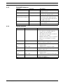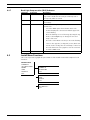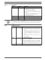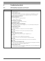
1
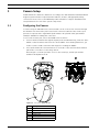
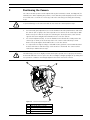
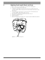
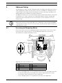
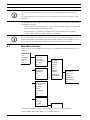
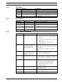
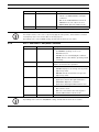
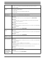
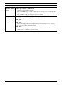
AutoDome 100 Series Fixed Camera
VG5 100 Series
en
User Manual
AutoDome 100 Series Fixed Camera
Table of Contents | en
3
Table of Contents
1
Camera Setup
4
1.1
Configuring the Camera
4
2
Positioning the Camera
5
3
Adjusting Focal Length (Zoom) and Focus
6
4
Advanced Setup
7
4.1
Accessing and Navigating Menus
7
4.2
Main Menu Function
8
4.2.1
Main Menu
9
4.2.2
ALC Submenu
9
4.2.3
ALC -> SHUTGAIN Submenu
4.2.4
ALC -> SHUTGAIN -> DAY/NIGHT Submenu
10
4.2.5
ENHANCED Submenu
11
4.2.6
COLOR Submenu
11
4.2.7
Back Light Compensation (BLC) Submenu
12
4.3
Install Menu Functions
12
4.3.1
Install Menu
13
4.3.2
CAMERA ID Submenu
13
5
Troubleshooting Guide
14
5.1
VG5 AutoDome Operation and Control
14
Bosch Security Systems, Inc.
9
User Manual
F.01U.216.346 | 1.0 | 2011.04
4
1
en | Camera Setup
AutoDome 100 Series Fixed Camera
Camera Setup
Install and wire the 100 Series AutoDome according to the VG5 AutoDome Installation Manual.
A typical system includes a keyboard, matrix switcher, monitor, and appropriate wiring
connections. Please refer to the individual product manuals for complete installation and
setup instructions for each of the system components.
1.1
Configuring the Camera
To assist setup, the VG5-100 Series camera module can be connected to a monitor through
the miniature 2.5 mm monitor jack located on the camera circuit board. The monitor jack
provides a composite video signal with synchronization. An optional cable (part number
S1460) is available for making this connection.
To access the monitor jack, remove the bubble and covert liner:
1.
Insert a small screw driver through the keyway in the Pendant trim-ring, rotate the dome
bubble counterclockwise and remove the dome bubble. For In-Ceiling AutoDomes, you
must loosen the small screw in the trim ring before rotating the bubble.
2.
Press and hold the two retention buttons on each side of the camera module and then
pull off the covert liner. See the image below.
Removing the covert liner provides access to the menu keys, and the pan and tilt
thumbscrew adjustment locks.
Figure 1.1
Ref
1
2
3
4
5
6
F.01U.216.346 | 1.0 | 2011.04
100 Series Camera Module
Description
Front View
Back View
Retention Button (2)
Covert Liner
Menu Keyboard
Monitor Jack
User Manual
Bosch Security Systems, Inc.
AutoDome 100 Series Fixed Camera
2
Positioning the Camera | en
5
Positioning the Camera
The camera module position can be adjusted along the horizontal, vertical, and diagonal (for
azimuth) axes. When adjusting the position, ensure that the picture displayed on the monitor
is level. After the covert liner is removed, position the camera by performing the following
steps:
WARNING!
To prevent damage to the camera module do not rotate the camera past its stops.
1.
For horizontal (pan) adjustment, loosen the thumbscrew at the platform base and rotate
the camera (left or right) to the desired position. The camera can be rotated up to 360º
between stops. If it hits the stop before achieving the desired position, rotate it in the
opposite direction. Retighten the thumbscrew to secure the camera.
2.
For vertical adjustment (tilt), loosen the thumbscrew at the tilt wheel and position the
camera (up or down) to the desired position. The camera can be tilted up to 110º
between stops. Retighten the thumbscrew to secure the camera.
3.
To compensate for angled ceilings or sidewall mounts, push the camera inward toward
its base and rotate it until the image on the monitor is horizontal. The camera can be
rotated up to 300º between stops.
CAUTION!
The CCD image sensors are highly sensitive and require special care for proper performance
and extended lifetime. Do not expose it to direct sunlight or bright spotlights in operating and
non-operation conditions. Avoid bright lights in the field of view of the camera.
Figure 2.1 Camera Position Adjustments
Ref
1
2
3
4
Bosch Security Systems, Inc.
Description
Camera Module Lock Tab
Horizontal (pan) Thumbscrew
Tilt Wheel Thumbscrew
Diagonal Adj.
User Manual
F.01U.216.346 | 1.0 | 2011.04
6
3
en | Adjusting Focal Length (Zoom) and Focus
AutoDome 100 Series Fixed Camera
Adjusting Focal Length (Zoom) and Focus
To adjust the camera lens focal length and focus, perform the following steps:
1.
2.
Select Set Focus Now from the Install menu.
To adjust the focal length, loosen the focal (zoom) lock screw and rotate the lens
mechanism (WIDE or TELE.) until you achieve the desired field of view. (Item 1, in the
figure below).
3.
To focus the image on the monitor, loosen the focus lock screw and turn the lens
mechanism (NEAR or FAR) until the image is in focus.
4.
Repeat both these adjustments until the desired view is in focus.
5.
Tighten both adjustment screws.
6.
Exit the Install menu.
7.
Remove the monitor jack and replace the covert liner and dome bubble when finished.
Figure 3.1
F.01U.216.346 | 1.0 | 2011.04
Focus and Zoom Adjustment
User Manual
Bosch Security Systems, Inc.
AutoDome 100 Series Fixed Camera
4
Advanced Setup | en
7
Advanced Setup
The VG5-100 Series camera module normally provides an optimal picture without the need for
further adjustments. Advanced setup options, however, are available for obtaining the best
results from the camera under special circumstances. There are two upper level On-Screen
Display (OSD) menus: the Main menu and the Install menu.
The Main menu allows you to select and setup the picture enhancement functions. The Install
menu allows you to set the camera ID, focus and synchronization settings. The Main and
Install menus have settings that you can select directly or open to submenus for a more
detailed setup.
NOTICE!
Active menu selections can vary depending or the combination of camera, CPU and COMM
(communication) modules used. The menu selections described in this manual are typical for
a VG5-100 Series system.
4.1
Accessing and Navigating Menus
There are five (5) keys used for navigating through the various menus. To access the setup
menus, press the center Select key to open and display the Main menu. Use the four
directional keys to navigate through the menus.
Figure 4.1
Ref
1
2
3
4
Menu Keyboard and Monitor Jack
Description
Menu Keyboard
Monitor Jack
Up Button
Left Button
Ref
5
6
7
Description
Select Button
Right Button
Down Button
Use the menu keys to perform the following:
–
To access the Main menu or to select a sub-menu item, press the center Menu Select key.
–
To open the Install menu press the Menu Select key for approximately 1.5 seconds.
–
To scroll up or down a menu press the Up or Down keys.
–
To move through options or to set parameters, press the Left or Right keys.
Bosch Security Systems, Inc.
User Manual
F.01U.216.346 | 1.0 | 2011.04
8
en | Advanced Setup
AutoDome 100 Series Fixed Camera
NOTICE!
To restore a selected menu item to its factory default, quickly press the Menu Select key
twice.
To exit the OSD menus from any menu item, hold down the Menu Select key until the OSD
disappears.
The VG5-100 Series also supports a variety of remote methods to make camera adjustments,
including the following:
–
A Universal keyboard using Bilinx over coax or UTP. For example, using a Bosch DiBos 8,
a Bilinx capable DIVAR, or an Allegiant system.
–
A PC running the optional Bosch Configuration Tool for Imaging Devices (CTFID)
software with a USB Bilinx adapter (Part No. VP-CFGSFT).
NOTICE!
To prevent unauthorized changes to the camera settings, the camera menu buttons can be
disabled using Bilinx communication through the CTFID software. Select the Online Config
button, then select the Miscellaneous branch and set Camera Buttons to Disable.
4.2
Main Menu Function
This section provides a graphical representation of the Main menu and descriptions for all
functions.
MAIN Menu
ALC
ENHANCE
COLOR
BLC
EXIT
ALC
ALC LEVEL
SHUT GAIN
PEAK AVERAGE
ALC SPEED
EXIT
ENHANCED
AUTO BLACK
SHARPNESS
DNR
XF-DYN
EXIT
SHUTGAIN
SHUTTER
DEFSHUT
FIXSHUT
SENSUP
GAIN
MAXGAIN
FIXGAIN
DAY/NIGHT1
NIGHTSENSE
EXIT
COLOR
WHITE BALANCE
WB SPEED
RED (GAIN)
GREEN
BLUE (GAIN)
SAT
EXIT
BLC
BLC
BLC LEVEL
BLC AREA
EXIT
DAY/NIGHT
DAY/NIGHT
SWITCH LVL
PRIORITY
IR CONTRAST
MONO BURST
EXIT
AREA
1. Available in Day/Night version cameras only, other versions show NightSense.
2. Only available when White Balance is set to Manual mode.
F.01U.216.346 | 1.0 | 2011.04
User Manual
Bosch Security Systems, Inc.
AutoDome 100 Series Fixed Camera
4.2.1
Advanced Setup | en
Main Menu
Function
ALC
ENHANCE
COLOR
BLC
Selections
Selects Submenu
Selects Submenu
Selects Submenu
ON, OFF, or selects submenu
Description
Accesses the Auto Level Control menu.
Accesses the Picture Enhancement menu.
Accesses the Color Control menu.
–
Enables Back Light Compensation (BLC).
–
Accesses the BLC submenu.
Exits this menu.
EXIT
4.2.2
9
ALC Submenu
Function
ALC LEVEL
SHUTGAIN
PEAK AVERAGE
Selections
(-15 to +15)
Selects Submenu
(-15 to +15)
Description
Adjusts the video output level.
Accesses the Shutter and Gain control menu.
Adjusts the balance between peak and average
ALC SPEED
ON, OFF, or selects
video control.
Adjusts the speed of the video level control loop.
submenu
EXIT
4.2.3
Returns to the MAIN menu.
ALC -> SHUTGAIN Submenu
Function
SHUTTER
Selections
AES, FL, FIXED
Description
–
AES (Auto Electronic Shutter): The camera
automatically sets the optimum shutter
speed.
–
FL (Flickerless): Avoids interference from
light sources.
–
DEFSHUT
FIXED: Allows the user to define the
1/60 (1/50), 1/100, 1/120,
shutter speed.
The camera tries to maintain the selected
1/250, 1/500, 1/1000,
shutter speed as long as the light level of the
1/2000, 1/5000, 1/10K
scene permits.
(Only available if SHUTTER is set to AES
FIXSHUT
SENSUP
1/60 (1/50), 1/100, 1/120,
mode.)
Selects the shutter speed. (Only available if
1/250, 1/500, 1/1000,
SHUTTER is set to FIXED mode.)
1/2000, 1/5000, 1/10K
OFF or (2x to 10x)
Selects the sensitivity factor the camera is set
to. (Only available if SHUTTER is set to AES
GAIN
mode.)
–
AGC mode: The camera automatically sets
AGC, FIXED
the gain to the lowest possible value
needed to maintain a good picture.
–
FIXED mode: The gain is set at a
MAXGAIN
(0 to 26)
predefined value.
Selects the maximum value the gain can have
FIXGAIN
(0 to 26)
during AGC operation.
Selects the gain setting. (Only available if GAIN
DAY/NIGHT3
Selects submenu
is set to FIXED mode.)
Accesses the Day/Night Control menu.
Bosch Security Systems, Inc.
User Manual
F.01U.216.346 | 1.0 | 2011.04
10
en | Advanced Setup
AutoDome 100 Series Fixed Camera
Function
NIGHTSENSE
Selections
AUTO, OFF, FORCED
Description
–
UTO mode: Camera automatically
switches to NIGHTSENSE in low light
conditions.
–
OFF mode: NIGHTSENSE is turned off.
–
FORCED mode: The camera is set to
NIGHTSENSE (black and white) mode.
Returns to the ALC menu.
EXIT
3. Only available in Day/Night version cameras, color versions show NightSense.
NOTICE!
If SensUp is active, some noise or spots may appear in the picture. This behavior is normal.
SensUp may cause some motion blur on moving objects.
Depending on the camera GAIN setting, unrelated menu items are not active.
4.2.4
ALC -> SHUTGAIN -> DAY/NIGHT Submenu
Function
DAY/NIGHT
Selections
Description
AUTO, COLOR, MONO –
AUTO: Switches the filter between COLOR
and MONO depending on the scene
illumination level.
–
COLOR: Use for normal daylight conditions.
–
MONO: Removes the IR filter, providing full IR
SWITCH LEVEL
(-15 to +15)
sensitivity.
Sets the video leveling threshold when the camera
PRIORITY
COLOR, MOTION
switches to monochrome operation.
in AUTO mode:
–
COLOR: Displays a color image as long as the
light level permits.
IR CONTRAST
NORMAL, ENHANCED
–
MOTION: Avoids motion blur as long as the
–
light level permits.
NORMAL: Optimizes contrast in monochrome
applications with visible light illumination.
MONO BURST
ON, OFF
–
ENHANCED: Optimizes contrast in
–
applications with high IR illumination levels.
ON: The color burst remains active, even in
Monochrome mode.
–
OFF: The color burst in the video signal is
switched OFF in Monochrome mode.
Returns to the SHUTGAIN menu.
EXIT
NOTICE!
Depending on the camera’s DAY/NIGHT setting, unrelated menu items are not active.
F.01U.216.346 | 1.0 | 2011.04
User Manual
Bosch Security Systems, Inc.
AutoDome 100 Series Fixed Camera
4.2.5
Advanced Setup | en
11
ENHANCED Submenu
Function
AUTO BLACK
Selections
ON, OFF
Description
ON: Automatically increases the
SHARPNESS
(-15 to +15)
visibility of details.
Adjusts the sharpness of the picture.
DNR
AUTO, OFF
Zero (0) is the default position.
AUTO: Automatically reduces the noise
(Dynamic Noise Reduction)
in the picture. This option may cause
some motion blur with moving objects.
XF-DYN
OFF, LOW, MID, HIGH
picture contrast.
Returns to the MAIN menu.
EXIT
4.2.6
OFF: DNR is turned off.
XF-DYN mode: Automatically optimizes
COLOR Submenu
Function
Selections
Description
WHITE BALANCE ATW, AWB HOLD, MANUAL –
ATW (Automatic White Balance): Allows
the camera to constantly adjust for
optimal color reproduction.
–
AWB HOLD: Puts the ATW on hold and
saves the color settings.
–
MANUAL: Allows the red, green and blue
gain to be set manually to a desired
WB SPEED
Slow, Medium, Fast
position.
Adjusts the speed of the white balance
RED-GAIN
(-5 to +5)
control loop when in ATW mode
–
In ATW mode: Adjusts the red gain to
optimize white.
RED
GREEN
(-30 to +30)
(-5 to +5)
–
In Manual mode: Adjusts red gain.
In Manual mode: Adjusts the green gain. (Not
BLUE-GAIN
(-5 to +5)
available in ATW mode.)
–
In ATW mode: Adjusts the blue gain to
BLUE
SAT
(-30 to +30)
(-15 to +5)
–
In Manual mode: Adjusts the blue gain.
Adjusts the color saturation. (-15 produces a
optimize white.
monochrome picture.)
Returns to the MAIN menu.
EXIT
Bosch Security Systems, Inc.
User Manual
F.01U.216.346 | 1.0 | 2011.04
12
en | Advanced Setup
4.2.7
AutoDome 100 Series Fixed Camera
Back Light Compensation (BLC) Submenu
Functions
BLC
Selections
ON, OFF
Description
ON: The video level optimizes the selected area of the
image. Parts outside this area may be underexposed or
BLC LEVEL
(-15 to +15)
overexposed, which is normal.
Adjusts the balance between the selected BLC area and its
BLC AREA
Selects submenu
surroundings.
Accesses the Back Light Compensation area menu. To size
the BLC area:
–
Select the AREA option from the BLC menu. The
monitor displays the current area with the upper left
corner flashing.
–
Move the flashing corner of the image by using the Up,
Down, Left and Right keys to change the size and
shape of the area.
–
Press the center Menu Select key to move the flashing
cursor to the opposite (or diagonal) corner, which can
now be used to change the size and shape of the area.
–
to exit the AREA menu.
Returns to the MAIN menu.
EXIT
4.3
Press the Menu Select key again to save the area and
Install Menu Functions
This section provides a graphical representation of the Install menu and descriptions for all
functions.
INSTALL Menu
CAMERA ID
SET FOCUS NOW
COMM
SYNC
DEFAULTS
EXIT
INSTALL CAMERA ID
CAMERA ID
ID POSITION
EXIT
INSTALL SYNC
SYNC
VPHASE
EXIT
INSTALL DEFAULTS
RESTORE ALL?
EXIT
F.01U.216.346 | 1.0 | 2011.04
User Manual
Bosch Security Systems, Inc.
AutoDome 100 Series Fixed Camera
4.3.1
Advanced Setup | en
13
Install Menu
Function
Selections
CAMERA ID
Selects submenu
SET FOCUS NOW
Description
Accesses the Camera ID submenu.
Completely opens the lens iris for best focus. The
recommended focus procedure is:
–
Unlock the focus locking screw.
–
From the INSTALL menu highlight SET FOCUS
–
Turn the lens focus adjustment as required
–
Tighten the lens focus locking screw.
NOW.
COMM
SYNC
DEFAULTS
EXIT
ON, OFF
Selects submenu
Selects submenu
–
Exit the menu selection.
Turns on Bilinx communication. See notice below.
Accesses the synchronization functions.
Returns all settings for all modes to their default.
Exits this menu.
NOTICE!
When using Bilinx control, the COMM ON/OFF menu selection is not active. This function can
be accessed only through the camera menu keys when the CTFID software is not actively
running.
4.3.2
CAMERA ID Submenu
Function
CAMERA ID
Selections
Selects submenu
Description
To enter up to a 17-character camera name:
–
Press the Menu Select key to enter the Camera ID
string.
–
Enter up to a 17-character string name for the camera.
–
Use the Up and Down keys to select a character.
–
Use the Left and Right keys to change position in the
string.
–
Press the Menu Select key to save and to exit the
character string.
ID POS
OFF, TOP, BOT
–
Exit the Camera ID menu.
Use left or right keys to select:
OFF: Camera ID not displayed.
TOP: Camera ID displayed at upper left corner of display.
BOT: Camera ID displayed at lower left corner of display.
(The camera ID is not displayed when the OSD menu is
EXIT
Bosch Security Systems, Inc.
open.)
Returns to the INSTALL menu.
User Manual
F.01U.216.346 | 1.0 | 2011.04
14
en | Troubleshooting Guide
AutoDome 100 Series Fixed Camera
5
Troubleshooting Guide
5.1
VG5 AutoDome Operation and Control
Problem
Solution
No video
–
Check that the Green LED on the AutoDome CPU board is on. This LED indicates video
from the camera.
If the Green LED is off, then:
–
Check that the Red LED on the AutoDome CPU board is slowly blinking. This LED
indicates power to the AutoDome power supply board and to the CPU Module.
Red LED on AutoDome CPU Module
Flash SequenceIndicates:
–
5 sec. on / 0.5 sec. off: Normal operation
–
Steady on: CPU is locked
If the Red LED is on steady, then:
–
Try cycling the AutoDome power off and on.
If the Red LED is off, then:
If using a Bosch Pendant Power Supply Box:
–
Check that Green LED in Power Supply Box is on. This LED indicates mains power
through the transformer.
If the Green LED is off, then:
–
Turn off the Power.
–
Check the FX101 fuse for mains power to the Power Supply Box.
If O.K., then:
–
Check the FX102 fuse for 24 V power to the AutoDome Pendant.
If O.K., then:
If using a non-Bosch power supply:
–
Check that the mains power to the power supply box is on.
If O.K., then:
–
Check that there is 24 V output from the transformer.
–
Check the connector on top of the AutoDome housing for bent pins.
If O.K., then:
–
Check the integrity of all wires and terminal connections to the AutoDome.
If O.K., then:
If there is power to the AutoDome, then:
–
Remove the camera and CPU modules from the AutoDome housing and check that the
Green LED on the housing power supply board is on.
If the Green LED is off, then:
–
Check that the fuse on the housing power supply board is good. (Try replacing the unit,
if an extra camera module is available.)
F.01U.216.346 | 1.0 | 2011.04
User Manual
Bosch Security Systems, Inc.
AutoDome 100 Series Fixed Camera
Local Keys Disabled
–
Troubleshooting Guide | en
15
This message appears if the Camera Menu Keyboard has been disabled through the
CTFID tool. Select OnLine Config>Installer Options>Miscellaneous>Camera
Buttons>Disable
No Remote Menu
–
Ensure that all coax, fiber and Ethernet cables are properly connected. See the VG5
AutoDome Installation Manual.
Access
If O.K., then:
–
Check if you can access the AutoDome OSD menus.
If O.K., then:
Intermittent Remote –
Check that all wiring meets Bosch recommended standards, specifications and
Camera Access
distances. See the VG5 AutoDome Installation Manual.
Picture is dark
–
Check that the Gain Control is set to AUTO (ON-43-ENTER).
If O.K., then:
–
Check that the Auto Iris Level is set to the appropriate level (ON-11-ENTER).
If O.K., then:
–
Check that the video coax is terminated with 75 Ω only at the head end. (Double
termination causes dark video.)
If O.K., then:
–
Check that the camera lens cover is removed.
If O.K., then:
–
Check that the maximum coax distance has not been exceeded. See the VG5 AutoDome
Installation Manual.
If O.K., then:
–
Restore all camera settings (ON-40-ENTER).
Colors are not
–
Reset the White Balance to the appropriate selection (ON-30-ENTER).
correct
If O.K., then:
–
Check that the maximum coax distance has not been exceeded. See the VG5 AutoDome
Installation Manual.
If O.K., then:
–
Restore the default settings (ON-40-ENTER).
–
Turn on backlight compensation (ON-20-ENTER).
Video is rolling,
–
Ensure that the Synch Mode is set to Internal (OFF-42-ENTER).
noisy or distorted
If O.K., then:
Background is too
bright to see subject
–
Check that the maximum coax distance has not been exceeded. See the VG5 AutoDome
Installation Manual.
If O.K., then:
–
Check the integrity of all BNC connectors and splices.
Note: Connecting a network cable to the interface board of a non-IP AutoDome causes
video distortion.
–
Remove the network cable from the interface board RJ-45 connector.
If O.K., then:
–
Contact Bosch Technical Support.
Day/Night camera
–
Check that the Day/Night mode is set to AUTO (ON-56-ENTER).
does not switch
If O.K., then:
automatically when
–
Set Gain Control to AUTO (ON-43-ENTER).
image is dark
Bosch Security Systems, Inc.
User Manual
F.01U.216.346 | 1.0 | 2011.04
16
en | Troubleshooting Guide
AutoDome 100 Series Fixed Camera
Inside of
–
EnviroDome bubble
If status reports Heater No Power, then:
Check the status of the Heater Module (ON-66-ENTER).
is foggy
–
Turn off the power to the AutoDome.
–
Check the FX103 fuse in the Power Supply Box for power (24 V) to the heater module.
If O.K., then:
–
Check all wiring and connector pins to the heater module.
Low Voltage flashing –
If using a non-Bosch power supply, confirm that it meets the Bosch AutoDome power
on monitor display
ratings. See the AutoDome Datasheet for specifications.
If O.K., then:
–
Check the mains input line voltage.
If O.K., then:
–
Check that the maximum wire length from the power supply has not been exceeded.
See the VG5 AutoDome Installation Manual.
If O.K., then:
–
Measure the AC voltage input to the camera while power is applied to the camera. The
voltage must be ≥ 21 VAC to stop the message.
F.01U.216.346 | 1.0 | 2011.04
User Manual
Bosch Security Systems, Inc.
Bosch Security Systems, Inc.
850 Greenfield Road
Lancaster, PA 17601
U.S.A.
www.boschsecurity.com
© Bosch Security Systems, Inc., 2011