1
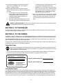
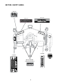
Operator’s
Manual
60" Mid Mount Mower Deck
Model 59A40009727
Cub Cadet Yanmar LLC
P.O. Box 361052
Cleveland, Ohio 44136-1052
PRINTED IN U.S.A.
769-03187
(7/07)
Table of contents
Important Safe Operation Practices ................................................................................................................ 2
To the Dealer and Owner ................................................................................................................................ 4
Safety Labels . ................................................................................................................................................. 5
Contents .......................................................................................................................................................... 6
Installlation and Removal ................................................................................................................................ 7
Adjustments . .................................................................................................................................................. 14
Deck Maintenance . ......................................................................................................................................... 17
Deck & Subframe Parts List ............................................................................................................................ 20
Section 1: important safe operation practices
This symbol points out important safety instructions which, if not followed, could endanger the personal safety and/or
property of yourself and others. Read and follow all instructions in this manual before attempting to operate this machine.
Failure to comply with these instructions may result in personal injury. When you see this symbol—HEED ITS WARNING.
This mower deck was built to be operated according to the rules for safe operation in this manual. As with any type of power
equipment, carelessness or error on the part of the operator can result in injury. This mower deck is capable of amputating
hands and feet or throwing objects. Failure to observe the following safety instructions could result in serious injury or death.
GENERAL OPERATION
11. Turn off blades when not mowing.
12. Stop the engine and wait until the blades come to a complete
stop before (a) removing the grass catcher or unclogging
chute, or (b) making any repairs, adjusting or removing any
grass or debris.
13. Mow only in daylight or good artificial light.
14. Do not operate the machine while under the influence of
alcohol or drugs.
15. Watch for traffic when operating near or crossing roadways.
16. Use extra care when loading or unloading the machine onto
a trailer or truck. Be sure truck is wide enough and on a firm,
level surface. Use loading ramps and attach them properly to
the truck bed. Use a heavy-duty trailer to transport the tractor.
17. Never make a cutting height adjustment while the engine is
running if the operator must dismount to do so.
18. Wear sturdy, rough-soled work shoes and close-fitting slacks
and shirts. Do not wear loose fitting clothes or jewelry. They
can be caught in moving parts. Never operate a unit in bare
feet, sandals or sneakers.
19. Check overhead clearance carefully before driving under
power lines, wires, bridges or low hanging tree branches,
before entering or leaving buildings, or in any other situation
where the operator and/or roll bar may be struck, which could
result in serious injury.
20. Disengage the power take-off, set the parking brake and shift
into neutral before attempting to start the engine.
21. Your mower is designed to cut normal residential grass. Do not
attempt to mow through unusually tall, dry grass (e.g. pasture)
or piles of dry leaves. Debris may build up on the mower deck,
presenting a potential fire hazard.
22. Use only accessories approved for the machine by Cub Cadet
Yanmar. Read, understand and follow all instructions provided
with approved accessories.
1. Read, understand and follow all instructions in the manual
and on the machine before starting. Keep this manual in a
safe place for future and regular reference and for ordering
replacement parts
2. Only allow responsible individuals familiar with the instructions
to operate the machine. Know the controls and how to stop the
machine quickly.
3. Do not put hands or feet under the cutting deck or near
rotating parts.
4. Clear the area of objects such as rocks, toys, wire, etc. which
could be picked up and thrown by the blades. A small object
may have been overlooked and could be accidentally thrown
by the mower in any direction and cause injury to you or a
bystander. To help avoid a thrown objects injury, keep children,
animals, bystanders and helpers at least 75 feet from the
mower while it is in operation. Always wear safety glasses
with side shields or safety goggles during operation or while
performing an adjustment or repair, to protect eyes from
foreign objects. Stop the blades when crossing gravel drives,
walks or roads.
5. Be sure the area is clear of other people before mowing. Stop
machine if anyone enters the area.
6. Never carry passengers.
7. Disengage the blades before shifting into reverse and backing
up. Always look down and behind before and while backing.
8. Be aware of the mower and attachment discharge direction
and do not point it at anyone. Do not operate the mower
without either the entire grass catcher or the chute guard in
place.
9. Slow down before turning. Operate the machine smoothly.
Avoid erratic operation and excessive speed.
10. Never leave a running machine unattended. Always turn off
the blades, place the transmission in neutral, set the parking
brake, stop the engine and remove key before leaving the
area.
SLOPE OPERATION
5. Never allow children under 14 years old to operate the
machine. Children 14 years and older should only operate
the machine under close parental supervision and proper
instruction.
6. Use extra care when approaching blind corners, shrubs, trees
or other objects that may obscure your vision of a child or
other hazard.
7. Remove the key when the machine is left unattended to
prevent unauthorized operation.
1. Slopes are a major factor related to loss of control and tip-over
accidents, which can result in severe injury or death. All slopes
require extra caution. If you cannot back up the slope or if
you feel uneasy on it, do not mow it.
2. For your safety, use the slope gauge (provided in tractor
Operator’s Manual) to measure slopes before operating the
unit on a sloped or hilly area. If the slope is greater than 15
degrees, as shown by the slope gauge, do not operate the unit
on that area or serious injury could result.
SERVICE
DO:
1. Use extreme care in handling gasoline and other fuels. They
are extremely flammable and the vapors are explosive.
a. Use only an approved container.
b. Never remove fuel cap or add fuel with the engine hot
or running. Allow the engine to cool at least two minutes
before refueling.
c. Replace the fuel cap securely and wipe off any spilled
fuel before starting the engine as it may cause a fire or
explosion.
d. Extinguish all cigarettes, cigars, pipes and other sources
of ignition.
e. Never refuel the machine indoors because fuel vapors
will accumulate in the area.
f. Never store the fuel container or machine inside where
there is an open flame or spark, such as a gas hot water
heater, space heater or furnace.
2. Never run a machine inside a closed area. Engine exhaust
fumes can be lethal.
3. To reduce fire hazard, keep the machine free of grass, leaves
or other debris build-up. Clean up oil or fuel spillage. Allow the
machine to cool at least 5 minutes before storing.
4. Before cleaning, repairing or inspecting, stop the engine and
remove key. Make certain the blades and all moving parts
have stopped.
5. Frequently check all nuts, bolts and screws for proper
tightness to ensure the equipment is in safe working condition,
especially the blade nuts. Also visually inspect blades for
damage (e.g., excessive wear, bent, cracked). Replace only
with blades that meet original equipment specifications.
6. Never tamper with safety devices. Check their proper operation regularly. Use all guards as instructed in this manual.
7. After striking a foreign object, stop the engine and thoroughly
inspect the mower for any damage. Repair the damage before
restarting and operating the mower.
8. Mower blades are sharp and can cut. Wrap the blades or wear
gloves, and use extra caution when servicing blades.
9. Check brake operation frequently. Adjust and service as
required.
10. Muffler and engine become hot during operation and can
cause a burn. Allow to cool down before touching.
11. Do not change the engine governor settings or overspeed the
engine. Excessive engine speeds are extremely dangerous.
Mow up and down slopes, not across.
Remove obstacles such as rocks, limbs, etc.
Watch for holes, ruts or bumps. Uneven terrain could overturn the
machine. Tall grass can hide obstacles.
Use slow speeds. Choose a low enough gear so that you will not
have to stop or shift while on the slope. Always keep the machine
in gear when going down slopes to take advantage of engine
braking action.
Follow the manufacturer’s recommendations for wheel weights or
counterweights to improve stability.
Use extra care with grass catchers or other attachments. These
can change the stability of the machine.
Keep all movement on the slopes slow and gradual. Do not make
sudden changes in speed or direction. Rapid engagement or
braking could cause the front of the machine to lift and rapidly flip
over backwards which could cause serious injury.
Avoid starting or stopping on a slope. If the tires lose traction,
disengage the blades and proceed slowly straight down the slope.
DO NOT:
Do not turn on slopes unless absolutely necessary. If necessary,
turn slowly and gradually across and down slope, if possible.
Do not mow near drop-offs, ditches or embankments. The mower
could suddenly turn over if a wheel is over the edge of a cliff or
ditch, or if an edge caves in.
Do not mow on wet grass. Reduced traction could cause sliding.
Do not try to stabilize the machine by putting your foot on the
ground.
CHILDREN
Tragic accidents can occur if the operator is not alert to the
presence of children. Children are often attracted to the machine
and the mowing activity. Never assume that children will remain
where you last saw them.
1. Keep children out of the mowing area and in watchful care of
an adult other than the operator.
2. Be alert and turn the machine off if children enter the area.
3. Before and when backing up, look behind and down for small
children.
4. Never carry children, even with the blades off. They may fall
off and be seriously injured or may interfere with safe machine
operation.
12. If the machine should begin to vibrate abnormally, stop the
engine and check immediately for the cause. Abnormal
vibration is a warning of trouble.
13. Observe proper disposal laws and regulations. Improper
disposal of fluids and materials can harm the environment and
the ecology.
a. Prior to disposal, contact your local Environmental
Protection Agency to determine the proper method
for disposing of the waste. Recycling centers are
established to properly dispose of materials in an
environmentally safe fashion.
b. Use proper containers when draining fluids. Do not use
food or beverage containers that may mislead someone
into drinking from them. Properly dispose of the containers immediately following the draining of fluids.
c. DO NOT pour oil or other fluids into the ground, down a
drain or into a stream, pond, lake, or other body of water.
Observe Environmental Protection Agency regulations
when disposing of oil, fuel, coolant, brake fluid, filters,
batteries, tires and other harmful waste.
14. We do not recommend the use of a pressure washer or garden
hose to clean your unit. They may cause damage to electrical
components; spindles; pulleys; bearings; or the engine. The
use of water will result in shortened life and reduce serviceability.
WARNING - YOUR RESPONSIBILITY: Restrict the use of this power machine to persons who read, understand and follow
the warnings and instructions in this manual and on the machine.
section 2: TO THE dealer
The initial assembly and proper installation of this attachment is the responsibility of the Cub Cadet Yanmar dealer. Read the instructions
and safety precautions found in this manual carefully.
section 3: to the owner
This Operator’s Manual is an important part of your new Mid Mount 60" Mower Deck. Contained in this manual are instructions covering
installation, safe operation, and maintenance of the Model 59A40009727 60 inch mower deck. Please read and understand what it says.
The Model 59A40009727 Mid Mount 60" Mower Deck is designed for use only with certain Cub Cadet Yanmar tractor models. It will
NOT fit nor operate safely or properly on or with any other tractor.
References to LEFT and RIGHT indicate the left and right sides of the tractor when facing forward in the operator’s position. Reference to
the FRONT indicates the grille end; to the REAR the drawbar end.
Finding Model Number
Before you start assembling your new equipment, please locate the model plate on the equipment and copy the information
from it in the space provided below. The information on the model plate is very important if you need help from our Customer
Support Department or an authorized dealer.
• You can locate the model number by looking on the top surface of the deck assembly. A sample model plate is shown below. For
future reference, please copy the model number and the serial number of the equipment in the space below.
Model Number
Serial Number
xxxxxxxxxxxxx
xxxxxxxxxxxxx
Cub Cadet/YanmarLLC
P.O. Box 361052
CLEVELAND, OHIO 44136
Copy the model number here:
Copy the serial number here:
www.cubcadetyanmar.com
Dealer Locator Phone Number: 877-282-5055
Calling Customer Support
If you have difficulty with this mower deck; have any questions regarding the controls, operation or maintenance of this equipment; or
desire additional information not found in this manual, contact your nearest authorized Cub Cadet Yanmar dealer. If you need assistance
in locating a dealer in your area, contact the Customer Dealer Referral Line. Call Call 1-(877) 282-5055 to reach the Customer Dealer
Referral Line. Please have your tractor’s model number and serial number, and the mower deck model number, ready when you call. See
your tractor operator’s manual to locate this information. For more details about your unit, visit our website at www.cubcadetyanmar.com.
• KEEP HANDS AND FEET AWAY FROM ROTATING PARTS.
• REMOVE OBJECTS THAT CAN BE THROWN BY THE
BLADE IN ANY DIRECTION. WEAR SAFETY GLASSES.
• DO NOT MOW WHEN CHILDREN OR OTHERS ARE AROUND.
NEVER CARRY CHILDREN EVEN WITH BLADES OFF.
• USE EXTRA CAUTION ON SLOPES. DO NOT MOW SLOPES
GREATER THAN 15°. MOW UP AND DOWN, NOT ACROSS.
AVOID SUDDEN TURNS, USE LOW SPEED.
S30503
ASSEMBLE CHUTE DEFLECTOR TO THIS UNIT BEFORE OPERATING.
WARNING
SHIELD MISSING
DO NOT OPERATE.
READ OPERATOR'S MANUAL. KEEP SAFETY DEVICES IN PLACE AND WORKING.
S30015
(QTY 2) 777S32328
Under Each Belt Guard
DANGER
777D11275
777D11371
KEEP HANDS AND FEET AWAY.
DO NOT OPERATE MOWER
UNLESS CHUTE DEFLECTOR
OR ENTIRE GRASS CATCHER IS
IN ITS PROPER PLACE.
section 4: safety labels
777D10728
60
CUT
TO REDUCE THE RISK OF INJURY, DO NOT
OPERATE UNLESS DISCHARGE COVER OR
GRASS CATCHER IS IN ITS PROPER PLACE.
IF DAMAGED, REPLACE IMMEDIATELY.
777S30015
777S30145
777S30503
SECTION 5: CONTENTS
The mower deck attachment components are listed below along with their part numbers. Assemblies are made up of more than one part
and do not have a part number. Before beginning installation, lay all components out on a flat surface to assure everything is present.
Throughout the manual the parts in the hardware pack will be identified by name, followed by their callout number in parenthesis, to aid in
installation.
3
2
20
If not Factory
Installed
19
18
1
3
14
15
13
16
4
9
6
17
11
12
7
10
5
8
Figure 1
1. RH Subframe Assembly .................. N/A
2. LH Subframe Assembly ...................... N/A
3. Rear Lift Rod Assembly ...................... N/A
(May have been factory installed)
4. Hex Cap Screw M16-20 x 35 ............... 710-04697
5. Hex Cap Screw, M16-2.0 x 60 ............ 710-04700
6. Hex Cap Screw, 5/8-11 x 2.5 .............. 710-04129
7. Flat Washer, .64 x 1.12 x .125 .............. 736-0366
8. Hex Lock Nut, 5/8-11 .......................... 712-3016
9. Spacer 1.25 OD x .625 ....................... 750-04877
10. Spacer 1.25 OD x 1.25 ........................ 750-04878A
11. RH Loader Adapter Bracket ................. 603-04441
1 pc
1 pc
2 pc
12. LH Loader Adapter Bracket ................. 603-04440
13. RH Lift Bracket Assembly ................... N/A
14. LH Lift Bracket Assembly .................... N/A
15. Spacer .625 ID x 4.95 Lg ..................... 750-04858
16. Nozzle Adapter ................................... 721-04041
17. Mid PTO Cover ................................... 703-06201
18. Hx Cp Scrw - May be factory installed .. 710-04706
19. Flat Washer - May be factory installed..736-0290
20. Hx Lck Nut - May be factory installed ...712-0261
Not Shown - Complete Deck Assembly ......
2 pc
2 pc
2 pc
4 pc
2 pc
2 pc
2 pc
2 pc
6
2 pc
1 pc
1 pc
2 pc
1 pc
1 pc
2 pc
2 pc
2 pc
1 pc
Section 6: Installation MOWING and Removal
Unpacking the Mower Deck
• insert the hex screw through the ball joint and fasten with the
hex lock nut (20). Tighten the hex lock nut until almost snug
against the ball joint. Do not overtighten. Refer to Figure 2.
Repeat the above procedure to install the other rear lift rod
assembly on the other subframe assembly.
Move the tractor and mower deck to a firm flat area large enough
to accommodate both. Allow enough room to slide the deck
underneath the tractor from the right side.
To uncrate the mower deck and all components, refer to Figure 1
and proceed as follows:
• Carefully remove the top of the shipping crate. Cut the ties
and remove the subframe assemblies from the packaging
shelf. Set the subframe assemblies aside.
• Support the subframe shelf and carefully remove the sides of
the crate. Cut or fold down the plastic bag.
• Remove the hardware pack from the shipping pallet. Check
the contents of the hardware pack against the list on page 6.
NOTE: Some hardware pack components may have been stored
in their mating parts for shipping purposes, and may not be in the
hardware pack.
• Carefully remove and discard any banding wire, strapping, or
tie straps securing the components to the shipping pallet.
• Carefully roll the deck off of the shipping pallet and remove
any ties and padding material.
Changing the Subframe Mounting Brackets
If a front loader is installed, or to be installed, on the tractor, the
subframe mounting brackets must be removed from the subframe
and replaced with the loader adapter brackets. If no front loader is
installed, or to be installed, skip to the following sub section.
• Remove the hex screw fastening the LH front subframe link
on the subframe pivot shaft, and slide the subframe link off of
the shaft. Refer to Figure 3.
• Withdraw the pivot shaft from the bearings in the subframe
rail. See Figure 3.
LH Subframe Shown
Subframe
Pivot Shaft
Hex Screw
Preparing Subframe Assembly
Hex Screw
Install Rear Lift Rods (if not already assembled)
NOTE: The rear lift rod may have been connected to the rear lift
arm of the each subframe assembly at the factory. If the rods are
connected, disregard the following instructions and skip to the
next subsection.
• Insert the hex screw (18) through the hole at the top of the
subframe rear lift arm on either the RH or LH subframe
assemblies (1 or 2, Figure 1). Slide the flat washer (19) onto
the screw.
• Looking at either of the rear lift rod assemblies, locate the flattened areas on the rod near the RH threaded end of the rod.
Position the rear lift rod assembly (3, See inset box of Figure
1) so that the flats of the rod, and RH threaded ball joint, are
toward the rear of the subframe assembly. Refer to Figure 2.
• Position the LH threaded ball joint at the other end of the rear
lift rod assembly between the top of the subframe rear lift arm
and the subframe rail. See Figure 2.
LH Subframe
Mtg. Bracket
Flange Lock Nut
LH Subframe
Front Lift Arm
Figure 3
• Remove the four hex flange lock nuts and screws securing the
LH subframe mounting bracket to the subframe rail to remove
the mounting bracket. See Figure 3.
• Position the LH loader adapter bracket (12) to align its four
holes with the four holes in the plate on the subframe rail.
Refer to Figure 3. Insert the four hex screws and thread the
hex flange lock nuts onto the screws. Tighten the flange lock
nuts until almost snug. Do not fully tighten the fasteners.
Flat Washer
Lock Nut
• Insert the subframe pivot shaft through the subframe rail and
slide the LH front subframe link onto the end of the shaft.
Align the holes in the subframe link with the hole in the pivot
shaft and insert the hex screw removed earlier. Fully tighten
the hex screw. Refer to Figure 3.
Rear Lift Rod
Hex Screw
RH Threaded
Ball Joint
LH Loader
Adapter Bracket
Subframe Rear
Lift Arm
• Repeat the above procedure to install the RH loader adapter
bracket (11) onto the RH subframe assembly (16).
• If not already installed, install the RH and LH loader mounts
on the tractor now by following the instructions in the front
loader operator’s manual.
Rod Flats
Figure 2
Preparing the tractor
• Locate the three holes in a triangular pattern on the tractor’s
clutch housing. Remove the protective plugs from the lower
two holes. Refer to Figure 5.
• Raise the front of the RH subframe assembly and align its two
upper holes with the two lower holes of the clutch housing.
Insert the two hex cap screws(4) and thread into the clutch
housing. Do not fully tighten now. Refer to Figure 5.
WARNING!: Engage the tractor parking brake,
stop the tractor engine and remove the key to
safely install the mower deck.
Installing Subframe and Lift Bracket Assemblies
NOTE: The RH and LH subframe assemblies can be installed
without removing the rear wheels. But limited space to remove
and reinstall fasteners makes it more difficult and increases the
possibility of an improper installation. It is recommended that the
respective rear wheel be removed from that side of the tractor
when installing the RH or LH subframe assembly.
• ONLY If the RH Loader Mount is installed. Remove the two
lower screws fastening the rear of the loader mount to the
tractor clutch housing. Align the upper holes of the RH loader
adapter bracket (installed on RH subframe assembly earlier)
with the loader mount holes. Insert the longer hex screws(5)
and thread into the clutch housing. Do not fully tighten now.
Scrap (or store for possible future use) the screws removed
from the loader mount.
WARNING!: When raising any part of the tractor
from the ground, use appropriate jack stands to
support the tractor. Do not work on the tractor
when supported only by a lifting jack.
Installing RH Subframe and RH Lift Bracket Assemblies
• Use a jack to raise the right rear of the tractor so that the tire
is off of the ground. Position a jack stand to support the tractor. Remove the right rear tire from the tractor and roll aside.
• If a lower hitch link sway spring is installed between the two
lift links of the 3-point hitch, unhook the chain from the links.
• Remove the klik pin from the end of lower hitch link pin.
While supporting the sway chain clevis links, slide the link pin
inward (to the left) to disengage the pin from the two clevis
links and the hitch link pin support bracket. See Figure 4.
Hex Cap
Screw
Clutch
Housing
Loosen
Fasteners
RH Subframe
Mounting Brkt.
Klik Pin
Lower Hitch
Link Pin
Figure 5
Hex Screws
• Lift the rear of the RH subframe assembly and align the three
holes in the rear subframe mtg./link pin support bracket with
the three holes in the RH rear axle housing. Insert the shorter
hex screws removed earlier and thread partially into the axle
housing holes. Do not tighten the screws now. See Figure 6
RH Lower
Hitch Link
Hitch Link Pin
Support Brkt.
Spacer
Hex Screw
Sway Chain
Clevis Link
Figure 4
• Continue to slide the hitch link pin to the left to remove the
spacers and disengage the RH lower hitch link. See Figure 4.
• Remove the four screws (3 short and 1 long) securing the
hitch link pin support bracket to the tractor’s RH rear axle
housing and remove the support bracket. Retain the four
screws and discard (or store) the bracket and spacers.
• Position the RH subframe assembly (1) along the right side of
the tractor.
• Loosen, but do not remove the four hex flange lock nuts and
screws securing the subframe mounting bracket to the plate
on the front of the subframe rail. Refer to Figure 5.
Spacer
Rear Subframe Mtg./
Link Pin Support Brkt.
Figure 6
• Place a 4.95" long spacer (15) between the rear subframe
mtg./link pin support bracket and the transmission housing,
and align with the holes in both as shown in Figure 6. Insert
the long hex screw removed earlier through the bracket and
spacer and thread into the transmission housing, but do not
fully tighten.
• Working from the rear of the tractor, slide the RH lower hitch
link pin almost fully to the left.
• Hold the RH lift bracket assembly (13) so that its shorter
side is to the left (toward transmission housing) and pointing
downward. Slide the shorter side of the lift bracket just onto
the hitch link pin. See Figure 7.
• Evenly tighten all the screws fastening both the front and
rear subframe mounting brackets to secure the RH subframe
assembly to the tractor. Re-tighten the four hex screws
and flange lock nuts to secure the front subframe mounting
bracket to the subframe rail.
• Reinstall the right rear tire, raise the tractor and remove the
jack stand, and lower the tractor to the ground.
Installing LH Subframe and LH Lift Bracket Assemblies
• Use a jack to raise the left rear of the tractor so that the left
rear tire is off the ground. Position a jack stand to support the
tractor and remove the left rear wheel.
• To install the LH subframe assembly (2), refer to Figures 4
through 7 and follow the instructions for installing the RH
subframe, adapting the instructions to the left side of the
tractor.
Rear Subframe Mtg./
Link Pin Support Brkt.
RH Lower Hitch
Link Pin
• The LH lift bracket assembly (14) is installed in the same
manner as the RH lift bracket assembly. Refer to Figure 7
and adapt the previous instructions to the left side of the
tractor to install the LH lift bracket assembly.
RH Lift Brkt.
Assembly
RH Lower
Hitch Link
• Evenly tighten all the screws fastening both the front and
rear subframe mounting brackets to secure the LH subframe
assembly to the tractor. Re-tighten the four hex screws
and flange lock nuts to secure the front subframe mounting
bracket to the subframe rail.
Klik Pin
Long Spacer
NOTE: If the sway spring was removed from the tractor’s 3-point
hitch lower hitch links, reconnect the spring to the lower hitch
links now.
Sway Chain
Clevis Link
Short Spacer
Installing Mid PTO Cover
• From the rear of the tractor, locate the two rearmost hex
screws in the bottom/left of the transmission housing.
Remove the two screws. Refer to Figure 8.
Figure 7
• Pivot the forward end of the RH lower 3-point hitch link
upward between the two sides of the lift bracket and align with
the hitch link pin. Slide the hitch link pin to the right until just
through the hitch link. Refer to Figure 7.
• Place the short spacer (.625" long) between the lower 3-point
hitch link and the longer side of the lift bracket; then slide the
hitch link pin to the right through the spacer and fully through
the lift bracket. Refer to Figure 7.
• Position the mid PTO cover so that it cups the mid PTO
linkage at the left lower/rear of the transmission, and align
its two mounting holes with the holes in the bottom of the
transmission housing. See Figure 8.
• While continuing to slide the hitch link pin to the right, slide
the long spacer (1.125" long) onto the pin. Refer to Figure 7.
• Lift the sway chain assembly and separate the two sway
chain clevis links to position a link on the inside and outside
of the rear subframe mtg./link pin support bracket. Align the
holes of the clevis links with the hole in the mounting bracket;
then slide the hitch link pin toward the right through the clevis
links and mounting bracket. Refer to Figure 7.
• Make sure the dowel pin on the left end of the hitch link pin
aligns with the slot in the hub of the retainer bracket on the
transmission housing and slide the pin fully to the right.
Hex
Screw
Mid PTO
Cover
• Fully insert the klik pin (removed earlier) into the hole of the
RH lower hitch link pin, and pivot the klik pin ring over the end
of the hitch link pin to lock in position. Refer to Figure 7.
Figure 8
• Reinstall the two hex screws and fully tighten to secure the
mid PTO cover on the transmission housing.
Attaching Rear Lift Rod Assembly
NOTE: If a lift rod assembly is too short to align the ball joint and
lift bracket holes, refer to “Adjusting the Rear Lift Rod Assemblies”
below and turn the rod as shown in Figure 11 to lengthen the rod
assembly as needed to connect to the lift bracket.
NOTE: The forward end of the rear lift rod assemblies should
already have been attached to the subframe lift arms. If not yet
attached, refer to the instructions at the beginning of this section
to attach the forward ends of the rod assemblies.
The rearward end of the rear lift rod assemblies must be connected to the just installed RH and LH lift bracket assemblies. The
lift rod assemblies were pre-adjusted at the factory, but will require
additional adjustment after installation.
To connect the lift rod assemblies to the lift bracket assemblies,
proceed as follows:
• Check that the LH and RH subframe rear lift arms are pinned
up in their respective lockout brackets on the subframe
assemblies (Refer to Figure 9). If the lift arms are not locked
in the up position, manually pivot the rear lift arms forward
and upward until each arm is up inside the lockout bracket
on the subframe. Remove the lockout pin from the storage
holes in each subframe assembly and insert the lockout pin
fully through the lockout bracket, beneath the rear lift arm, to
secure the lift arm in the up position. See Figure 9.
• Slide a flat washer (7) onto the hex screw (6) and insert the
hex screw through the ball joint. Slide a second flat washer
(7) onto the hex screw, and insert the screw through the lift
bracket. Secure with the hex lock nut (8). See Figure 10.
Lift Bracket
Assembly
Rear
Lift Rod
Hex
Lock Nut
Flat Washer
Flat Washer
RH Thread
Ball Joint
Storage
Hole
Hex screw
Figure 10
• Move to the other side of the tractor and repeat the previous
instructions to connect the rear lift rod to the lift bracket on the
other side of the tractor.
Clevis Pin
Adjusting the Rear Lift Rod Assemblies
LH Subframe
Rear Lift Arm
Proper adjustment of the lift rod assemblies is attained when, with
the deck not installed and the tractor 3-point hitch links raised to
their highest position, the subframe rear lift arms almost contact
the upper surface of their respective subframe lockout brackets
(Refer to Figure 9). To correctly adjust the rear lift rods, proceed
as follows:
• Make certain the tractor 3-point hitch arms are raised to their
highest postion.
• Working from the rear of the tractor, loosen the jam nut from
against the right hand thread ball joint by turning the jam nut
clockwise as shown in Figure 11. Turn the nut away from the
ball joint.
Lockout
Bracket
Figure 9
• From the back of the tractor, check that the two lower 3-point
hitch links are level side to side and that both are held inward
by the sway chains and spring. If the hitch links are not level,
follow the instructions in the tractor operator’s manual to
adjust the RH lift link to level the hitch links.
WARNING!: Follow all warnings and procedures
provided in the tractor operator’s manual for
safely starting the tractor engine.
Rear Lift
Bracket
• Start the tractor engine and use the 3-point hitch control
lever (refer to the tractor operator’s manual) to raise the lower
3-point hitch links to their highest position. Stop the
engine.
Use 9/16" Wrench
on Rod Flats
Rear Lift Arm
Lengthen
Rod
NOTE: If the 3-point hitch links move very slowly, refer to the
tractor operator’s manual and check the tractor hydraulic flow
control/stop knob adjustment.
Shorten
Rod
• Working at either the right, or left, rear of the tractor, grasp the
rear lift rod assembly and pull the rod as necessary to align
the ball joint hole with the hole at the bottom of the lift bracket.
Refer to Figure 10.
RH Thread
Ball Joint
Loosen
Jam Nut
Figure 11
10
• Use a 9/16" open end wrench on the flats of the lift rod to turn
the lift rod in the direction shown in Figure 11 to shorten the
lift rod assembly.
• While observing the position of the rear lift arm in the lockout
bracket, continue to turn the lift rod until the rear lift arm
almost contacts the upper surface of the lockout bracket
(Refer to Figure 9). When the lift rod is properly adjusted,
tighten the jam nut against the ball joint. Refer to Figure 11.
• Move to the lift rod on the other side of the tractor and repeat
the previous instructions to properly adjust the other lift rod
assembly.
NOTE: Improper adjustment of the rear lift rods could result in
breakage of the shear bolts fastening the lift bracket assemblies.
If the deck will not raise correctly, check the lift bracket assembly
hex bolts and replace the hex bolt(s) as necessary.
• Remove the clevis pins holding the subframe lift arms up in the
lockout brackets on both subframe assemblies. Re-install the
clevis pin in the storage hole of each subframe. Refer to Figure 9.
• Start the tractor engine and use the 3-point hitch control lever
(refer to the tractor operator’s manual) to raise the lift arms to
their highest position. Stop the engine.
• Remove the internal cotter pins and clevis pins and raise
the front caster wheels to their highest position (lowest deck
height setting). NOTE: Refer to the Adjustments section
later in this manual for instructions on adjusting the position
of the deck caster wheels.
• Remove the internal cotter pin and withdraw the clevis pin
from the rear gauge wheel adjustment handle and index
bracket. Move the gauge wheels to their highest position
(lowest deck height setting).
• Use the tractor steering wheel to turn the front wheels of the
tractor all the way to the left. NOTE: It may be necessary to
momentarily start the tractor to fully turn the front wheels. Stop
the engine after turning wheels.
• From the right side of the tractor, maneuver the deck underneath the tractor. Slide the deck under the tractor until the
hitch brackets on the back of the deck approximately align
with the rear lift arms.
• Slide the deck forward, then use the 3-point hitch control
lever to lower the rear lift arms until the receiver slots of the
arms align with pins in the hitch brackets on the rear the deck.
Refer to Figure 13.
• Roll the deck rearward to fully engage the deck hitch bracket
pins in the receiver slots of the RH and LH rear lift arms.
Refer to Figure 13.
installing the mower deck
Connecting Mower Deck to Subframe
The mower deck should be installed from the right hand side of
the tractor. To install the deck onto the tractor, proceed as follows:
WARNING!: Follow all warnings and procedures
provided in the tractor operator’s manual for
safely starting the tractor engine.
• If the rear lift arms of the subframe assemblies are raised to
their highest position, start the tractor engine and use the 3point hitch control lever (refer to the tractor operator’s manual)
to lower the lift arms.
• From the right side of the tractor, pull the release pin of
the rear lift arm assembly out of the upper hole in the lock
bracket; then slightly pivot the pin so that it is held outward
against the side of the lock bracket. Refer to Figure 12.
Hitch Brkt. Pin
Deck Hitch
Bracket
Lock Bracket
• Slide the lock bracket up the lift arm until the lower hole in the
lock bracket aligns with the pin hole in the lift arm. Pivot the
release pin down to the lower hole and release so that the
pin goes through the lock bracket and lift arm to fix the lock
bracket in the raised (unlocked) position. See Figure 12.
Deck Hitch
Bracket
Lift Arm
Receiver
Slot
Lock Bracket
Rear Lift Arm
Release Pin
Figure 13
• From either side of the tractor, pull the rear lift arm release
pin out of the lower hole in the lock bracket and slide the lock
bracket downward to straddle the deck hitch bracket pin. Align
the upper hole in the lock bracket with the lift arm hole. Pivot
the release pin upward to the upper hole and release so that
the pin goes fully through the lock bracket and lift arm to fix
the lock bracket in the locked position. See Figure 13.
Release Pin
Figure 12
• Repeat the procedure on the left side of the tractor to fix the
lock bracket of the LH rear lift arm assembly in the raised
(unlocked) position.
11
• Move to the other side of the tractor and repeat the above
procedure to capture the deck hitch bracket pin in the rear lift
link on the other side of the tractor. Refer to Figure 13.
• Align the locking collar of the drive shaft with the mid - PTO
shaft and slide the drive shaft fully onto the PTO shaft. If
necessary, compress the locking collar of the drive shaft to
ease connecting the shaft.
• From either side of the tractor, remove internal cotter pin and
withdraw the clevis pin from the front lift link on the deck.
Refer to Figure 14.
NOTE: It may be necessary to turn the pulleys on the deck slightly
to align the splines of the drive shaft with those of the PTO shaft.
• Pivot the lift link upward so that it straddles the subframe front
lift arm. Align the holes and insert the clevis pin. Secure with
the internal cotter pin. See Figure 14.
Mid PTO
Shaft
Clevis
Pin
Front
Lift Arm
Drive
Shaft
Internal
Cotter Pin
Locking
Collar
Figure 15
• Pull the drive shaft to make sure it is locked onto the PTO
shaft. The drive shaft must not pull off of the mid - PTO shaft.
mowing
WARNING!: To avoid possible injury, never direct
the discharge of material toward bystanders or allow anyone near the machine while in operation.
Although the area has been supposedly cleared
of foreign objects, small objects may be picked
up and discharged by the mower.
Front
Lift Link
Figure 14
• Move to the other side of the tractor and connect the other
deck front lift link to the subframe lift arm as described in the
previous two steps.
NOTE: Prior to using the mower deck after installation, refer to the
adjustment and leveling instructions in Section 7 “Adjustments.”
Connecting Deck Drive Shaft
For best results it is recommended that the first two laps should
be cut with the discharge thrown towards the center. After the
first two laps, reverse the direction to throw the discharge to the
outside for the balance of cutting. This will give a better appearance to the lawn.
Do not cut the grass too short. Short grass invites weed growth
and yellows quickly in dry weather.
Mowing should be done with the engine operating at the RPM
recommended for the PTO powering the deck. Do not mow at high
ground speed.
During certain times of the year and under some conditions, the
mower may leave streaks of uncut grass.
Streaking may occur when attempting to mow heavy weeds and
tall grass. Under these conditions it may be necessary to go back
over the cut area a second time to get a clean cut.
The following practices will help eliminate streaking:
• Mow the area more often so the grass doesn’t get too tall and
heavy.
• Operate the tractor at the recommended RPM and at a slower
forward speed.
• Keep the blades sharp and replace the blades when worn.
WARNING!: Do not attempt to connect the drive
shaft when the tractor engine is running. Stop
the tractor engine, disengage all PTO controls,
engage the parking brake, and wait for all movement to stop before connecting the deck drive
shaft.
The deck drive shaft must be securely connected to the mid - PTO
shaft at the lower/front of the tractor’s transmission housing.
NOTE: The deck, subframe, and rear tires limit access to the
mid - PTO shaft. If you cannot connect deck drive shaft from the
side of the tractor, you will have to access the mid - PTO shaft from
the rear of the tractor, between the rear tires. Some 3-point hitch
attachments may have to be temporarily removed to allow you to
connect the deck drive shaft.
WARNING!: Never position any part of your body
beneath tractor implements held in the raised
position only by the tractor’s hydraulic system. A
sudden loss of pressure could cause the implement to fall and could result in severe injury.
• Position the deck drive shaft so that it faces rearward from the
deck gear box.
12
Using Subframe Lock out
WARNING!: Never position any part of your body
beneath tractor implements held in the raised
position only by the tractor’s hydraulic system. A
sudden loss of pressure could cause the implement to fall and could result in severe injury.
Removal of the mower deck is not necessary to utilize implements
attached to the 3 - point hitch. The subframe lock feature allows
the 3 - point hitch links to be raised and lowered without also
raising and lowering the mower deck.
NOTE: If accessing the deck drive shaft from the rear of the
tractor, it may be necessary to temporarily remove some 3 - hitch
attachments.
• Accessing the drive shaft from either the side or the rear of
the tractor, grasp the drive shaft locking collar and compress
toward the body of the shaft to release and slide the shaft
from the tractor’s mid - PTO shaft. Pivot the drive shaft to
the side so that it rests on top of the deck housing. Refer to
Figure 15.
• From each side of the tractor, remove the internal cotter pin
and withdraw the clevis pin to disconnect the front lift links
from the subframe front lift arms. Refer to Figure 14. Reinsert
the clevis pins into the deck front lift links and secure with the
internal cotter pins to store with the deck.
• From either side of the tractor, pull the release pin of the rear
lift arm assembly out of the upper hole in the lock bracket;
then slightly pivot the pin so that it is held outward against the
side of the lock bracket. Refer to Figure 12.
• Slide the lock bracket up the lift arm until the lower hole in the
lock bracket aligns with the pin hole in the lift arm. Pivot the
release pin down to the lower hole and release so that the
pin goes through the lock bracket and lift arm to fix the lock
bracket in the raised (unlocked) position. See Figure 12.
• Repeat the procedure on the other side of the tractor to fix
the lock bracket of the rear lift arm assembly in the raised
(unlocked) position.
• Roll the deck forward to disengage the deck hitch bracket
pins from the receiver slots of the RH and LH rear lift arms.
Refer to Figure 13.
• Start the tractor engine and use the 3-point hitch control lever
(refer to the tractor operator’s manual) to raise the lift arms to
their highest position, and turn the front wheels of the tractor
all the way to the left. Stop the engine.
• From the right side of the tractor, maneuver the deck out from
underneath the tractor.
• The subframe front and rear lift arms should be secured in the
locked out position when not in use. On each side of the tractor, withdraw the clevis pin from the storage hole at the middle
of the RH and LH subframe assemblies. Refer to Figure 9.
• From either side of the tractor, insert the clevis pin through
the lockout bracket, beneath the rear lift arm, to secure the lift
arm in the up position. See Figure 15.
• Move to the other side of the tractor and insert the other clevis
pin through the lockout bracket and rear lift arm. Secure with
the internal cotter pin. Refer to Figure 16.
To engage the deck lock out feature, proceed as follows:
• On each side of the tractor, withdraw the clevis pin from
the storage hole at the middle of the RH and LH subframe
assemblies. Refer to Figure 9.
• Start the tractor engine and use the 3-point hitch control lever
(refer to the tractor operator’s manual) to raise the lift arms to
their highest position. Stop the engine.
• From either side of the tractor, insert the clevis pin through
the lockout bracket, beneath the rear lift arm, to secure the lift
arm in the up position. See Figure 16.
Clevis Pin
Lockout
Bracket
LH Rear
Lift Arm
Figure 16
• Move to the other side of the tractor and insert the other clevis
pin through the lockout bracket to secure the lift arm in the up
position. Refer to Figure 16.
Removing the mower deck
If you choose to remove the mower deck from the tractor, proceed
as follows:
WARNING!: Do not attempt to disconnect the
drive shaft when the tractor engine is running.
Stop the tractor engine, disengage all PTO
controls, engage the parking brake, and wait for
all movement to stop before disconnecting the
deck drive shaft.
• Adjust the front caster wheels and rear gauge wheels to their
highest position (lowest deck position) and use the tractor
3-point hitch control lever to lower the deck to the ground.
Refer to “Adjustments” later in this manual.
Follow the instructions from the subsection “Installing the Mower
Deck” on page 11 to reinstall the mower deck after the initial
installation has been completed.
13
Section 7: Adjustments
Adjusting Deck gauge wheels
Adjusting the Rear Gauge Wheels
The 60" mower deck is equipped with ground following front
caster wheels and is designed to be operated with the front caster
wheels and rear gauge wheels on the ground. Consequently, the
adjusted position of the front caster wheels and rear gauge wheels
determine the cutting height.
There are six cutting height positions ranging from 1-1/4" to 5".
Adjust the front caster wheels and rear gauge wheels to the
desired cutting height before starting the engine to begin mowing.
The height adjustment handle on the left side of the deck is used
to adjust the position of the rear gauge wheels. The rear gauge
wheel index bracket on the deck also has six index holes, which
correspond to the six index holes of the caster wheel shaft.
When adjusting the rear gauge wheels, the height setting should
correspond to the selected setting for the front caster wheels. For
example, if the front caster wheels were adjusted to their lowest
index hole (lowest deck setting), the rear gauge wheels should be
adjusted to their highest setting (lowest deck setting). Adjust the
rear gauge wheels as follows:
WARNING!: Stop the tractor engine, disengage
all PTO controls, engage the parking brake, and
wait for all movement to stop before adjusting the
deck wheels.
• Use the tractor 3-point hitch control lever to raise the mower
deck so that the rear gauge wheels are off of the ground.
• Note which of the six shaft index holes the front caster wheels
are set in.
Adjusting the Front Caster Wheels
There six index holes in the caster wheel shafts that are approximately 3/4" apart. Consequently, each index hole adjustment
will raise, or lower, the mower deck approximately 3/4 of an inch.
To adjust the front gauge wheels, determine your desired cutting
height and proceed as follows:
• Remove the internal cotter pin from the clevis pin in the height
adjust handle.
• Grasp the height adjust handle and withdraw the clevis pin.
See Figure 18.
• Move the height adjust handle to the hole in the index bracket
that corresponds to the index hole used to adjust the front
caster wheels (the lower index bracket holes correspond
to the lower caster wheel shaft holes - higher index bracket
holes to higher caster wheel shaft holes). See Figure 18.
• Use the tractor 3-point hitch control lever to raise the mower
deck off of the ground.
• Working at the front caster wheel on either side of the deck,
remove the internal cotter pin from the clevis pin securing the
caster wheel shaft in the caster bracket. See Figure 17.
Caster
Bracket
Clevis Pin
Rear Gauge
Wheels
Caster
Wheel
Shaft
Index
Bracket (Raise Deck)
(Raise Gauge
Wheels)
(Lower Deck)
Internal
Cotter Pin
Internal
Cotter Pin
Height
Adjust
Handle
Clevis Pin
(Lower Gauge
Wheels)
Caster
Wheel
Figure 17
• Support the caster wheel and withdraw the clevis pin.
• Slide the caster wheel shaft up or down in the caster bracket
to the desired height setting and align the index hole with the
hole in the castor bracket. See Figure 17.
Figure 18
• Align the height adjust handle hole with the appropriate index
bracket hole and re-insert the clevis pin through the handle
and index bracket. Secure with the internal cotter pin. Refer to
Figure 18.
• Insert the clevis pin through the caster bracket and shaft, and
secure with the internal cotter pin.
• Note the index hole used for the just adjusted caster wheel,
and repeat the above procedure to adjust the other caster
wheel to the same position.
NOTE: Whenever the front caster wheel position is changed, the
rear gauge wheel position should also be adjusted.
14
LEVELING THE MOWER DECK
• Measure and record the distance from the level surface to
the outer-most cutting edge of the right blade. Repeat this
measurement for the left blade. If the two blade heights are
not within 1/16 inch, the deck must be leveled. Note which
blade had the larger distance between the cutting edge
and level surface.
• From the rear of the tractor, work on the rear lift rod assembly
on the side of the tractor with the larger ground to blade
cutting edge measurement.
• Loosen the jam nut from against the ball joint on the rear of
the rod assembly. See Figure 20.
Although the mower deck is designed to operate with the front
caster wheels and rear gauge wheels on the ground, some
mowing conditions may require the mower deck to be operated
with the deck wheels off the ground. To assure a quality cut in
those situations, the deck should be properly leveled. Correct
adjustment of the mower deck will level the deck from side to side,
and provide the correct front to back pitch of the mower deck.
The mower deck should be leveled during the initial installation
of the deck, and then periodically checked and re-adjusted as
necessary.
Use 9/16" Wrench
on Rod Flats
WARNING!: Before leveling the mower deck, position the tractor on a hard level surface, engage
the parking brake lever and turn ignition key to
the “OFF” position. ALWAYS stop the engine
after utilizing the tractor hydraulic lift system.
When handling the mower deck, be careful not to
cut yourself on the sharp blades.
Lengthen
Rod
Side to Side Leveling
Loosen
Jam Nut
Most of the side to side leveling of the mower deck is accomplished with minor adjustment of one of the rear lift rod assemblies.
However, the initial front to back adjustment of the front lift rod
assemblies may affect the side to side leveling. For the initial
leveling of the deck, perform the side to side leveling described
below, adjust the front to back pitch of the deck, then recheck the
side to side level and adjust as necassary.
Figure 20
• Use a 9/16" wrench on the flats of the lift rod to turn the lift rod
in the direction shown in Figure 19 to lengthen the rod. Turn
the rod only in small increments, while continuing to measure
the outer blade tip heights.
• When the blade tip heights are within 1/16" of each other,
re-tighten the jam nut against the ball joint.
NOTE: Check for proper tire inflation before checking and/or
making a leveling adjustment.
When the deck is properly leveled, the left and right blades will
have corresponding cutting-edge-to-ground measurements within
1/16 inch of each other.
Front to Back Leveling
The front of the mower deck should be approximately 1/4" lower
than the rear of the deck when hanging from the subframe with
the front caster wheels and rear gauge wheels off the ground.
The front lift rods are adjusted at the factory, but may require
additional adjustment when performing the initial installation of the
mower deck onto the tractor.
• Use the tractor hydraulic lift system to raise the deck so that
its wheels are off the ground. Stop the engine.
• Carefully rotate the outer cutting blades so that they are
positioned perpendicular to the tractor frame. See Figure 19.
WARNING!: Engage the parking brake and turn
ignition key to the “OFF” position. ALWAYS stop
the engine after utilizing the tractor hydraulic
lift system. When handling the mower deck, be
careful not to cut yourself on the sharp blades.
• Start the tractor engine and use the 3-point hitch control lever
(refer to the tractor operator’s manual) to raise the mower
deck so that its wheels are off the ground. Stop the engine.
Figure 19
15
• On each side of the tractor, use a 9/16" wrench on the flats
of each rod to turn the rod. Turn each rod as shown in Figure
22 to shorten the rod and raise the front of the deck, or to
lengthen the rod and lower the front of the deck.
• Adjust both front lift rods in small increments, while continuing
to re-measure the front and rear blade heights. When the
deck is approximately 1/4" lower in the front, re-tighten the
jam nuts against the front ball joints.
• Carefully turn the outer blades of the mower deck so that the
ends of the blades point to the front and rear of the deck. See
Figure 21.
Use 9/16" Wrench
on Rod Flats
Lengthen
Figure 21
• Measure the distance from the front cutting edge tip of the
blade to the ground. Then measure the distance from the
rear cutting edge tip to the ground. Repeat to measure the
outer blade on the other side of the deck. The front blade tip
measurement should be approximately 1/4" less than the rear
measurement, and the measurements should be approximately equal from side to side.
• If the difference between the front and rear blade tip heights
is greater than 1/4 inch, the front lift rods assemblies should
be shortened. If less than 1/4 inch, the rod assemblies should
be lengthened.
• If adjustment is necessary, loosen the jam nuts and turn them
away from the ball joints on the front end of the front lift rod
assembly on each side of the tractor. See Figure 22.
Shorten
Loosen
Jam Nut
Figure 22
• If performing the initial leveling of the mower deck, re-position
the blades and re-check the side to side level of the deck as
described in the previous sub section “Side to Side Leveling.”
16
Section 8: deck Maintenance
Blade care
Nozzle
Adapter
WARNING!: Stop the tractor engine, disengage
all PTO controls, engage the parking brake, and
wait for all movement to stop before adjusting the
deck wheels.
Adapter
Lock Collar
Pull Lock
Collar Back
The cutting blades must be kept sharp at all times. Inspect and
sharpen, or replace, the cutting blades as follows:
IMPORTANT: Sharpen the cutting edges of the blades evenly so
that the blades remain balanced and the same angle of sharpness
is maintained.
• Remove the mower deck from the tractor as described earlier
in this manual. Carefully tip the deck upward to access the
bottom of the mower deck.
• To remove the blades, use a 1-1/8 inch wrench to hold the
hex head of the spindle bolt, while using a second 1-1/8 inch
wrench to loosen the hex flange nut securing the blade.
NOTE: A block of wood may be placed between the deck
housing and the cutting edge of the blade to help in breaking
loose the hex flange lock nut securing the blade.
• Inspect each blade. The cutting blades should be kept sharp
at all times.
• Sharpen the cutting edges of the blades evenly so that the
blades remain balanced and the same angle of sharpness is
maintained.
• If the cutting edge of a blade has already been sharpened
many times, or if any metal separation is present, it is
recommended that a new blade be installed. New blades are
available at your authorized dealer.
• When replacing the blades, be sure they are installed so that
the wind wings are pointing upward toward the top of the deck
housing. Secure the hex head of the spindle bolt and tighten
the hex flange nuts to 90 to 110 ft-lbs. (122 to 149 N·m).
• After replacing the blades, apply grease the exposed threads
at the bottom of the spindle bolts to prevent rust buildup.
Deck Wash
Nozzle
Figure 23
• Turn on the water supply.
• From the tractor operator’s seat, start the engine and engage
the mid - PTO. Allow to run as needed. Disengage the PTO
and stop the engine.
• Turn off the water supply.
• Pull back the lock collar of the nozzle adapter to disconnect
the adapter from the nozzle.
• Connect the nozzle adapter and hose to the deck wash
nozzle on the right side of the deck, and repeat the previous
steps to clean the mower deck
Cleaning the Spindle Pulleys
Periodically remove the belt covers and remove any accumulated
grass clippings from around the spindle pulleys and the deck belt.
• Remove the three hex screws fastening the RH belt cover.
Refer to Figure 24.
cleaning the mower deck
Hex Screw
Using The Deck Wash System
Index
Bracket
WARNING!: When using the deck wash system,
never engage the deck from any position other
than the operator’s seat of the tractor. Do not
engage the deck if bystanders are in the area.
RH Belt
Cover
LH Belt
Cover
• Attach the nozzle adapter (16) to a standard garden hose
connected to a water supply.
• Move the tractor to an area within reach of the hose where the
dispersal of wet grass clippings is not objectionable to you.
Disengage the PTO, engage the parking brake, and stop the
engine.
Hex Screw
Figure 24
• Pull back the lock collar of the nozzle adapter and push the
adapter onto the deck wash nozzle at the left end of the
mower deck. Release the lock collar to lock the adapter on
the nozzle. Refer to Figure 23.
• Remove the two hex screws fastening the LH belt cover. Slide
the belt inward to disengage its tabs from the slots in the
index bracket on the deck. Refer to Figure 24.
17
• Clean away any grass clippings and debris that may have
collected around spindle pulleys and belt.
• The deck gear box is lubricated and sealed, and does not
require additional lubrication.
• Align the LH belt cover tabs with the slots in the index bracket
and push the cover outward so that the tabs are fully engaged
in the slots and the cover holes align with the speed nuts
on the cover brackets. Install the two hex screws and fully
tighten.
• Periodically lubricate the pivot hubs of the rear gauge wheel
adjustment shaft with a good grade of lubricating oil.
Lubricating the Subframe
The lift shafts of both the RH and LH subframe assemblies are
equipped with lube fittings.
• Position the RH belt cover to align its three holes with the
speed nuts on the cover brackets. Install the three hex screws
and fully tighten.
• After every 10 hours of operation, lubricate the two lift shafts
on both the RH and LH subframe assemblies with 251H EP
grease or an equivalent No. 2 multipurpose lithium grease.
See Figure 26.
lubrication
Lubricating the Mower Deck
Rear Lift Shaft
Lube Fitting
Always lubricate the deck thoroughly before taking it to the field.
Use a pressure lubricating gun to apply grease to the deck lube
fittings.
• After every 10 hours of operation and/or before putting the
deck into winter storage, lubricate the spindle assemblies and
the idler bracket with 251H EP grease or an equivalent No.
2 multipurpose lithium grease. Remove the plugs from the
RH and LH belt covers to access the two outer spindle lube
fitting. Refer to Figure 25.
Front Lift Shaft
Lube Fitting
• After every 50 hours of operation and/or before putting the
deck into winter storage, lubricate the drive shaft with 251HEP
grease or an equivalent No. 2 multipurpose lithium grease.
Refer to Figure 25.
Spindle
Lube
Fitting
Figure 26
Spindle
Lube
Fitting
Idler
Bracket
Lube
Fitting
Spindle
Lube
Fitting
Drive Shaft
Lube Fitting
Figure 25
18
spindle belt replacement
• Lift the gear box, slip the belt off and underneath the drive
pulley, and remove the belt from the deck.
A worn spindle belt will affect the quality of cut from the mower
deck and should be replaced. Referring to Figure 23, replace the
spindle belt as follows:
Install New Spindle Belt
• Lift the gear box assembly to install the belt around the drive
pulley.
• Position the gear box to align its four screw holes with the
gear box mounting bracket holes. Secure with the four hex
cap screws removed earlier.
• Route the backside of the belt around the back and right of
the movable flat idler pulley as shown in Figure 23.
• Loop the belt and route in front of the shoulder bolt toward
the left side of the deck. Slide the loop of the belt underneath
the LH belt cover mounting bracket, and place the belt in the
groove of the LH spindle pulley. See Figure 23.
• Then route the belt as follows:
1. Around the rear of the fixed flat idler pulley
2. Around the front of the center spindle pulley
3. To the right spindle pulley
• After making certain the spindle belt is properly engaged in
each pulley and that the backside of the belt is against the
shoulder bolt, pivot the movable flat idler pulley toward the left
side of the deck to relieve tension and to allow the belt to be
rolled onto the right hand spindle pulley.
• Install the belt covers and secure with the hex cap screws.
Remove Spindle Belt
• Remove the two hex screws securing the LH belt cover to the
deck. Slide the belt cover tabs from the slots of the deck index
bracket to remove the cover. Refer to Figure 20
• Remove the three hex cap screws securing the RH belt cover
and remove the belt cover.
• Observe the routing of the spindle belt to help ensure proper
installation of the new belt.
WARNING!: The idler arm and movable flat idler
pulley are under spring tension. Use caution
when handling the idler pulley.
• Push the movable flat idler pulley toward the left side of the
deck to relieve belt tension. Slip the spindle belt up and off
the movable flat idler pulley, then carefully release the flat
idler pulley.
• Slide the belt off and over the LH spindle pulley, then pull the
belt under the LH belt cover mounting bracket. See Figure 23.
• Slip the belt off the fixed flat idler pulley, center spindle pulley,
and RH spindle pulley.
• Remove the four hex cap screws securing the gear box to the
gear box mounting bracket on the deck.
Fixed
Flat Idler
Pulley
Shoulder
Bolt
Spindle
Pulley
Spindle
Pulley
Spindle
Belt
LH Belt Cover
Mntg. Bracket
Hex Cap
Screw
Spindle
Belt
Drive Pulley
Gear Box
Figure 23
19
Moveable
Flat Idler
Pulley
Section 9: deck & subframe parts list
Subframe
21
20
9
33
30
1
38
43
11
24
31
28
41
34
27
34
37
19
32
44
41
38
12
8
41
38
25
3
42
38
33
13
35
36
25
31
30
41
22
2
26
40
4
7
26
47
45
45
39
17
16
23
5
6
46
15
28
29
10
14
20
18
21
Subframe
Ref. Part
No. Number
Description
Qty.
Ref. Part
No. Number
Description
Qty.
1
603-04420
Shaft, Deck Subframe
2
25
710-3144
Screw, Hex Cap, 3/8-16 x 2.0 Gr5
4
2
603-04421
Arm, Front Lift RH
1
26
711-04845
Pin, .625 Dia.
2
3
603-04422
Arm, Front Lift LH
1
27
712-0261
Nut, Jam Lock, 5/8-16 GrA
2
4
603-04423A Rail, Subframe LH
1
28
712-04065
603-04424A Rail, Subframe RH
1
Nut, Hex Flange Insert Lock 3/8-16 GrF
10
5
6
603-04425
Arm, Rear Lift RH
1
29
712-3016
Nut, Hex Insert Lock, 5/8-11 Gr5
2
7
603-04426
Shaft, Rear Lift
2
30
712-3056
Nut, Hex Jam, 5/8-18 Gr5
4
8
603-04427
Arm, Rear Lift LH
1
31
714-04003
Pin, Internal Cotter, .125 x 2.5 Lg
4
9
603-04440
Bracket, Loader Adapter LH
1
32
714-0474
Pin, Cotter, .125 x .75
2
10
603-04441
Bracket, Loader Adapter RH
1
11
703-06026
Bracket, Subframe Mounting LH
1
12
703-06027
Bracket, Subframe Mounting RH
1
13
703-06095
Bracket, Lock Pin
2
14
703-06162
Bracket, Breakaway Lift RH
1
15
703-06163
Bracket, Breakaway Lift LH
1
16
703-06164
Bracket, Lift LH
1
17
703-06165
Bracket, Lift RH
1
18
703-06201
Cover, Mid PTO
1
19
710-04129
Screw, Hex Cap, 5/8-11 x 2.5
2
20
710-04697
Screw, Hex Cap, M16-2.0 x 35
4
21
710-04700
Screw, Hex Cap, M16-2.0 x 60
4
22
710-04706
Screw, Hex Cap, 5/8-11 x 1.75 Gr8
2
23
710-04712
Screw, Hex Cap, 3/8-16 x 1.25 Gr2
2
24
710-3005
Screw, Hex Cap, 3/8-16 x 1.25 Gr5
8
33
723-04050
Ball Joint, .625 ID x 5/8-18
4
34
723-04061
Ball Joint, .625 ID x 5/8-18 LH Thrd.
4
35
732-0306A
Spring, Compression, .531 x 1.75
2
36
736-0140
Washer, Flat, .385 x .62 x .063
2
37
736-0290
Washer, Flat, .625 x 1.0 x .067 HT
2
38
736-0366
Washer, Flat, .64 x 1.12 x .125
8
39
737-04091
Fitting, Lube
2
40
737-3000
Fitting, Lube
2
41
741-0558
Bearing, Flange, 1.0 x 1.125 x 1.62
8
42
747-04702
Rod, Deck Release
2
43
747-04831
Rod, 23.735 Lg LH/RH Thrd.
2
44
747-04832
Rod, 15.25 Lg LH/RH Thrd.
2
45
750-04858
Spacer, .625 x 4.95
2
46
750-04877
Spacer, 1.25 x .625
2
47
750-04878A Spacer, 1.25 x 1.25
2
Mower Deck
918-3129C
22
Mower Deck
Ref. Part
No. Number
Description
Qty.
Ref. Part
No. Number
Description
Qty.
1
603-04413
Bracket, Deck Wheel
2
42
714-0115
Pin, Cotter, 1/8 x 1.0
1
2
603-04416
Deck Housing
1
43
714-0117
Pin, Internal Cotter
2
3
603-04418
Handle, Wheel Height Adjustment
1
44
714-0128
Key, Square, 1/4 x 1.0
1
4
603-04419
Bracket, Caster Wheel Yoke
2
45
714-0147
Pin, Internal Cotter
3
5
603-04430
Link, Front Lift
2
46
714-04003
Pin, Internal Cotter
4
6
603-0662
Guard, Deck
1
47
716-0102
Ring, Snap
1
7
603-0848A
Bracket, Idler
1
48
716-0111
Ring, External Retaining
1
8
918-3129C
Spindle Assembly
3
49
717-04415
Gearbox
1
9
638-04012A
Bolt Assembly, Shoulder
1
50
717-04422
Shaft, Deck Drive
1
10
703-05658
Plate, Idler Support
1
51
721-04041
Adapter, Nozzle
1
11
703-06199
Cover, Belt RH
1
52
726-0211
Nut, Speed, 5/16-18
5
12
703-3248
Baffle, Deck
1
53
726-3045
Button, Plug
2
13
703-3250
Bracket, Chute Deflector
1
54
731-3005
Roller, Front
1
14
703-3273
Cover, Belt LH
1
55
731-3257
Deflector, Chute
1
15
710-0347
Screw, Hex Cap, 3/8-16 x 1.75 Gr5
1
56
732-0850
Spring, Extension, 1.0 x 6.14
1
16
710-0376
Screw, Hex Cap, 5/16-18 x 1/0 Gr5
6
57
732-0939
Spring, Torsion
1
17
710-0395
Screw, Hx Cap, 5/16-18 x 2.25 Gr5
1
58
734-04314
Wheel, Caste
4
18
710-0521
Screw, Hex Cap, 3/8-16 x 3.0 Gr8
1
59
736-0258
Washer, Flat, .385 x 1.0 x .135
2
19
710-0805
Screw, Hex Cap, 5/16-18 x 1.5 Gr5
4
60
736-0275
Washer, Flat, .344 x .688 x .065
1
20
710-1260A
Screw, Hex Wash. Hd Tapp
5/16-18 x .75
12
61
736-0291
Washer, Flat, .88 x 1.38 x .125 HT
1
21
710-1336A
Bolt, Spindle, 3/4-16 x 4.25
3
22
710-1638
Screw, Carriage, 1/2-13 x 4.5 Gr5
4
23
710-1649
Screw, Carriage, 3/8-16 x 4.25 Gr5
2
24
710-1880
Screw, Hx Patch, 5/16-18 x .75 Gr5
4
25
710-3168
Bolt, Carriage, 3/8-16 x 1.0
2
26
710-3178
Bolt, Carriage, 3/8-16 x .75
6
27
710-3251
1
62
736-0322
Washer, Flat, .45 x 1.25 x .164 HT
1
63
736-0354
Washer, Flat, .39 x .75 x .105
1
64
736-0362
Washer, Flat, .33 x 1.25 x .06 HT
1
65
736-04167
Washer, Flat, 1.063 x 2.5 x .16
1
66
736-0760
Washer, Lock
1
67
737-04003C
Nozzle, Deck Wash
2
68
737-3000
Fitting, Lube
3
69
738-03056
Bolt, Shoulder, .496 x 2.5:3/8-16
1
28
711-04715
Screw, Socket Hd, 5/16-18 x 1.75 Gr5
Pin, Clevis, .625 x 1.5
4
70
741-0941
Bearing, Ball
2
29
711-04729A
Shaft, Gauge Wheel
2
71
759-04013
Blade, High Lift
3
30
711-0679A
Pin, Clevis, 3/8 x 2.015
3
72
747-3384
Rod, Chute Deflector
1
748-3065A
Spacer, Spindle
6
31
711-1643
Pin, Clevis, 3/4 x 2.5
2
73
32
711-3314
Pin, Roller, 1/2 x 7.31
1
74
748-3087
Spacer, Idler
1
33
712-0290
Nut, Hex Lock, 7/16-14
1
75
750-0535
Spacer, .38 x .625 x .21
1
34
712-04063
4
76
750-3222
Axle, Caster Wheel
4
35
712-04065
77
754-3103
V Belt, B Section x 133
1
78
756-04292
Pulley, Drive
1
36
712-0429
Nut, Hex Insert Flange Lock, 5/16-18 GrF
Nut, Hex Insert Flange Lock, 3/8-16 GrF
Nut, Hex Insert Lock, 5/16-18 Gr5
1
79
756-3062
Pulley, Idler 5.0
2
5
37
712-0431
Nut, Hex Flange Lock, 3/8-16 GrF
7
80
756-3096
Pulley, Spindle
3
38
712-0641
Nut, Hex, M16 - 1.5
2
81
721-3018A
Seal, Oil
6
39
712-3046
Nut, Hex Jam Lock, 5/16-18
2
82
741-04129
Bearing, Cone
6
741-04130
Cup, Bearing
6
750-04409
Spacer, Bearing
3
40
712-3078
Nut, Hex Flange Lock, 3/4-16 Gr8
2
83
41
712-3083
Nut, Hex Insert Lock, 1/2-13 GrB
4
84