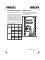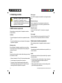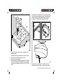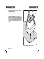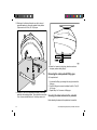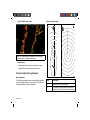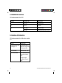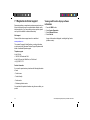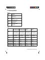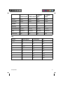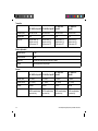
1
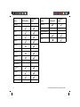
HD / SHD Digital
Open Array radar
Installation instructions
ENGLISH
Date: 12-2009
Document number: 87087-5
© 2009 Raymarine UK Limited
Trademarks and registered trademarks
Autohelm, HSB, RayTech Navigator, Sail Pilot, SeaTalk and Sportpilot are UK registered trademarks of Raymarine UK Limited.
Pathfinder and Raymarine are UK registered trademarks of Raymarine Holdings Limited. 33STV, 45STV, 60STV, AST, Autoadapt,
Auto GST, AutoSeastate, AutoTrim, Bidata, G Series, HDFI, LifeTag, Marine Intelligence, Maxiview, On Board, Raychart, Raynav,
Raypilot, RayTalk, Raystar, ST40, ST60+, Seaclutter, Smart Route, Tridata, UniControl, Hybridtouch, and Waypoint Navigation are
trademarks of Raymarine UK Limited.
All other product names are trademarks or registered trademarks of their respective owners.
Fair Use Statement
You may print no more than three copies of this manual for your own use. You may not make any further copies or distribute or use the
manual in any other way including without limitation exploiting the manual commercially or giving or selling copies to third parties.
Copyright ©2009 Raymarine UK Ltd. All rights reserved.
ENGLISH
Document number: 87087-5
Date: 12-2009
Contents
Chapter 1 Important information............................. 7
Certified Installation ........................................................
Transmitted power density levels .....................................
Water ingress .................................................................
EMC installation guidelines .............................................
Suppression ferrites ........................................................
Declaration of conformity.................................................
Product disposal .............................................................
Warranty registration.......................................................
IMO and SOLAS.............................................................
Technical accuracy .........................................................
Multifunction display software version ..............................
7
7
8
8
8
8
9
9
9
9
9
Chapter 2 Planning the installation ........................ 11
2.1 Handbook information ............................................... 12
2.2 Installation checklist .................................................. 12
2.3 Typical system examples ........................................... 13
2.4 Pack contents ........................................................... 15
2.5 Tools ........................................................................ 16
Chapter 3 Cables and connections......................... 17
3.1 General cabling guidance .......................................... 18
3.2 Radar scanner connection ........................................ 19
3.3 Product grounding..................................................... 19
3.4 Radar scanner power connections ............................. 21
3.5 Radar scanner data connections ................................ 22
3.6 Digital radar cable extension ...................................... 23
3.7 Digital radar cables ................................................... 24
3.8 VCM100 power connections ...................................... 25
3.9 VCM100 power cable extension ................................. 27
3.10 VCM100 screen (drain) wire extension ..................... 27
3.11 Circuit breaker and fuse ratings ................................ 28
3.12 Sharing a breaker.................................................... 28
Chapter 4 Location and mounting .......................... 29
4.1 Selecting a location ................................................... 30
4.2 Mounting .................................................................. 34
Chapter 5 System checks ........................................ 41
5.1 Radar scanner initial power on test............................. 42
5.2 Radar check ............................................................. 42
Chapter 6 Troubleshooting...................................... 45
6.1 Troubleshooting ........................................................ 46
6.2 Power up troubleshooting .......................................... 47
6.3 Radar troubleshooting ............................................... 48
6.4 System data troubleshooting...................................... 49
6.5 VCM100 LED indications ........................................... 50
6.6 SeaTalkhs LED indications.......................................... 50
5
Chapter 7 Technical support ................................... 51
7.1 Raymarine technical support...................................... 52
Chapter 8 Technical specification........................... 53
8.1 Technical specification............................................... 54
6
HD and SuperHD Digital Open Array Installation instructions
Chapter 1: Important information
Warning: Switch off power supply
Certified Installation
Ensure the boat’s power supply is switched OFF
before starting to install this product. Do NOT connect
or disconnect equipment with the power switched on,
unless instructed in this document.
Raymarine recommends certified installation by a Raymarine
approved installer. A certified installation qualifies for enhanced
product warranty benefits. Contact your Raymarine dealer for
further details, and refer to the separate warranty document packed
with your product.
Warning: Radar scanner safety
Warning: Product installation and
operation
This product must be installed and operated in
accordance with the Raymarine instructions provided.
Failure to do so could result in personal injury, damage
to your boat and/or poor product performance.
Warning: High voltages
This product contains high voltages. Do NOT remove
any covers or otherwise attempt to access internal
components, unless specifically instructed in this
document.
Before rotating the radar scanner, ensure all personnel
are clear.
Warning: Radio frequency radiation
hazard
The radar scanner transmits electromagnetic energy
at microwave frequencies which can be harmful,
particularly to the eyes. Do NOT look at the scanner
from close range. Ensure personnel are clear of the
scanner when it is powered on.
For safety reasons, the radar must be installed above
head height, out of range of personnel.
Transmitted power density levels
Warning: Product grounding
Before applying power to this product, ensure it has
been correctly grounded, in accordance with the
instructions in this guide.
Important information
• A power density level of 10 W/m2 is likely at distances of 34 cm
or less from the radar scanner.
• A power density level of 100 W/m2 does not occur at any point.
7
Water ingress
Water ingress disclaimer
Although the waterproof rating capacity of Raymarine products
exceeds that called for by the IPX6 standard, water intrusion
and subsequent equipment failure may occur if any Raymarine
equipment is subjected to commercial high pressure washing.
Raymarine will not warrant equipment subjected to high pressure
washing.
EMC installation guidelines
Raymarine equipment and accessories conform to the appropriate
Electromagnetic Compatibility (EMC) regulations, to minimize
electromagnetic interference between equipment and minimize the
effect such interference could have on the performance of your
system
and data loss which can occur if the engine start does not have
a separate battery.
• Raymarine specified cables are used.
• Cables are not cut or extended, unless doing so is detailed in
the installation manual.
Note: Where constraints on the installation prevent any of
the above recommendations, always ensure the maximum
possible separation between different items of electrical
equipment, to provide the best conditions for EMC performance
throughout the installation
Suppression ferrites
Correct installation is required to ensure that EMC performance is
not compromised.
Raymarine cables may be fitted with suppression ferrites. These
are important for correct EMC performance. If a ferrite has to be
removed for any purpose (e.g. installation or maintenance), it must
be replaced in the original position before the product is used.
For optimum EMC performance we recommend that wherever
possible:
Use only ferrites of the correct type, supplied by Raymarine
authorized dealers.
• Raymarine equipment and cables connected to it are:
– At least 1 m (3 ft) from any equipment transmitting or cables
carrying radio signals e.g. VHF radios, cables and antennas.
In the case of SSB radios, the distance should be increased
to 7 ft (2 m).
– More than 2 m (7 ft) from the path of a radar beam. A radar
beam can normally be assumed to spread 20 degrees above
and below the radiating element.
Declaration of conformity
Raymarine Ltd. declares that the HD and SuperHD Digital
Open Array radar scanners are in compliance with the essential
requirements of R & TTE directive 1999/5/EC.
The original Declaration of Conformity certificate may be viewed on
the relevant product page at www.raymarine.com
• The product is supplied from a separate battery from that used
for engine start. This is important to prevent erratic behavior
8
HD and SuperHD Digital Open Array Installation instructions
Product disposal
Technical accuracy
Dispose of this product in accordance with the WEEE Directive.
To the best of our knowledge, the information in this document was
correct at the time it was produced. However, Raymarine cannot
accept liability for any inaccuracies or omissions it may contain. In
addition, our policy of continuous product improvement may change
specifications without notice. As a result, Raymarine cannot accept
liability for any differences between the product and this document.
The Waste Electrical and Electronic Equipment (WEEE)
Directive requires the recycling of waste electrical and electronic
equipment. Whilst the WEEE Directive does not apply to some
Raymarine products, we support its policy and ask you to be aware
of how to dispose of this product.
Warranty registration
To register your HD and SuperHD Digital Open Array radar scanner
ownership, please take a few minutes to fill out the warranty
registration card found in the box, or visit www.raymarine.com and
register on-line.
It is important that you register your product to receive full warranty
benefits. Your unit package includes a bar code label indicating the
serial number of the unit. You should stick this label to the warranty
registration card.
IMO and SOLAS
The equipment described within this document is intended for use
on leisure marine boats and workboats not covered by International
Maritime Organization (IMO) and Safety of Life at Sea (SOLAS)
Carriage Regulations.
Important information
Multifunction display software version
To ensure optimum performance and compatibility with external
devices, your multifunction display must be using the latest software
version.
Visit www.raymarine.com to download the latest software.
Viewing multifunction display software
information
1.
2.
3.
4.
Press the MENU button.
Select System Diagnostics.
Select Software Services.
Select Unit Info.
A range of information is displayed, including the App Version
(software version).
Radar scanner feature compatibility
The following table lists the features supported by the Digital Open
Array radar scanner variants.
9
Feature
Gain presets:
All HD variants
All SuperHD
variants
Feature
All HD variants
All SuperHD
variants
Dual Range
— Buoy
— Harbor
Scanner rotation speed:
24 RPM
— Coastal
48 RPM
— Offshore
— Bird Mode
Antenna Boost
Power Boost
Enhance echoes:
— Interference
Rejection
— Expansion
— Wakes
10
HD and SuperHD Digital Open Array Installation instructions
Chapter 2: Planning the installation
Chapter contents
•
2.1 Handbook information on page 12
•
2.2 Installation checklist on page 12
•
2.3 Typical system examples on page 13
•
2.4 Pack contents on page 15
•
2.5 Tools on page 16
Planning the installation
11
2.1 Handbook information
2.2 Installation checklist
This handbook contains important information regarding the HD and
SuperHD Digital Open Array range of radar scanners.
Installation includes the following activities:
Installation Task
The handbook is for use with the following models:
• 48” and 72” 4kW HD Digital Open Array.
1
Plan your system
• 48” and 72” 12kW HD Digital Open Array.
2
Obtain all required equipment and tools
• 48” and 72” 4kW SuperHD Digital Open Array.
3
Site all equipment
• 48” and 72” 12kW SuperHD Digital Open Array.
4
Route all cables.
5
Drill cable and mounting holes.
6
Make all connections into equipment.
7
Secure all equipment in place.
8
Power on test the system.
Further information
For detailed operating instructions, refer to the handbook that
accompanies your multifunction display.
12
HD and SuperHD Digital Open Array Installation instructions
2.3 Typical system examples
3. GPM400 G-Series processor
The Digital Open Array radar scanner can be connected to a variety
of equipment as part of your marine electronics system.
4. VCM100 power converter
5. Power supply
6. G-Series display
Radar connected using SeaTalkhs switch
1
3
2
4
5
6
D11773-1
1. Digital Open Array radar scanner
2. SeaTalkhs switch
Planning the installation
13
Radar connected directly to multifunction display
1. Digital Open Array radar scanner
2. Multifunction display
3. Crossover coupler
4. VCM100 power converter
5. Power supply
1
2
4
3
5
D11772-1
14
HD and SuperHD Digital Open Array Installation instructions
2.4 Pack contents
1
Item
Description
Quantity
1
Pedestal
1
2
Mounting template
1
3
Denso paste
1
4
VCM100 Voltage Converter
Module
1
5
VCM100 cable clamp
1
6
Lifting eye
3
7
Stud
4
8
Plain washer
4
9
Spring washer
4
10
Nut
8
11
VCM100 mounting screw
2
12
VCM100 cable clamp mounting
screw
3
m
m ole
11 r h s)
ll te n
ri e io
D m sit
dia po
(4
C
le
ab
E
ntr
y
70
m
m
14
0
m
m
C
en
tr
e
of
R
ota
tio
n
um f
im o
ax e l
M tlin sta
ou de
pe
l te
ta la
es p
ed Tem
lP g
ita n
ig nti
D ou
M
15
0
m
m
R
FO
57
W
m
R
A
m
D
T
N l d
A sta li
T e g
R ed nin
p
PO re pe
o
IM ecu re
S fo
be
2
3
6
7
4
8
9
10
11
5
12
D11774-1
Planning the installation
15
2.5 Tools
Item
Description
Tools required for installation
1
Power drill
2
13 mm socket
3
17 mm socket
4
Screwdriver (“Pozidrive” head)
5
Adhesive tape
6
11 mm drill bit
7
3 mm drill bit
8
17 mm spanner
9
13 mm spanner
10
Torque wrench
3
2
1
4
6
5
7
8
9
10
D11775-1
16
HD and SuperHD Digital Open Array Installation instructions
Chapter 3: Cables and connections
Chapter contents
•
3.1 General cabling guidance on page 18
•
3.2 Radar scanner connection on page 19
•
3.3 Product grounding on page 19
•
3.4 Radar scanner power connections on page 21
•
3.5 Radar scanner data connections on page 22
•
3.6 Digital radar cable extension on page 23
•
3.7 Digital radar cables on page 24
•
3.8 VCM100 power connections on page 25
•
3.9 VCM100 power cable extension on page 27
•
3.10 VCM100 screen (drain) wire extension on page 27
•
3.11 Circuit breaker and fuse ratings on page 28
•
3.12 Sharing a breaker on page 28
Cables and connections
17
3.1 General cabling guidance
Always route data cables as far away as possible from:
• other equipment and cables,
Cable types and length
• high current carrying ac and dc power lines,
It is important to use cables of the appropriate type and length
• Unless otherwise stated use only standard cables of the correct
type, supplied by Raymarine.
• Ensure that any non-Raymarine cables are of the correct quality
and gauge. For example, longer power cable runs may require
larger wire gauges to minimize voltage drop along the run.
• antennae.
Strain relief
Ensure adequate strain relief is provided. Protect connectors from
strain and ensure they will not pull out under extreme sea conditions.
Routing cables
Circuit isolation
Cables must be routed correctly, to maximize performance and
prolong cable life.
Appropriate circuit isolation is required for installations using both
AC and DC current:
• Do NOT bend cables excessively. Wherever possible, ensure a
minimum bend radius of 100 mm.
• Always use isolating transformers or a separate power-inverter
to run PC’s, processors, displays and other sensitive electronic
instruments or devices.
• Always use an isolating transformer with Weather FAX audio
cables.
Minimum bend
200 mm (8 in)
diameter
Minimum bend of cable
100 mm (4 in) radius
• Always use an RS232/NMEA converter with optical isolation on
the signal lines.
• Always make sure that PC’s or other sensitive electronic devices
have a dedicated power circuit.
• Protect all cables from physical damage and exposure to heat.
Use trunking or conduit where possible. Do NOT run cables
through bilges or doorways, or close to moving or hot objects.
• Secure cables in place using tie-wraps or lacing twine. Coil any
extra cable and tie it out of the way.
Cable shielding
Ensure that all data cables are properly shielded that the cable
shielding is intact (e.g. hasn’t been scraped off by being squeezed
through a tight area).
• Where a cable passes through an exposed bulkhead or deckhead,
use a suitable watertight feed-through.
• Do NOT run cables near to engines or fluorescent lights.
18
HD and SuperHD Digital Open Array Installation instructions
3.2 Radar scanner connection
3.3 Product grounding
The power and data cable connector is at the rear of the radar
scanner unit.
Important safety information for connections to ground.
Ensuring that the arrow on the power and data cable connector is
aligned with the red triangular mark on the radar scanner connector,
connect the cable to the scanners’ connector, and fully hand-tighten.
Do NOT use a wrench or any other tool.
Before applying power to this product, ensure it has been correctly
grounded, in accordance with the instructions in this guide.
Grounding requirements
These grounding requirements are applicable for Raymarine
equipment supplied with a separate drain wire or screen.
• The product power cable drain conductor (screen) must be
connected to a common ground point.
Note: If the antenna connector is disconnected after initial
installation, Raymarine recommends that before reconnecting,
you lightly coat the connector thread with Renolit Aqua 2 Calcium
grease.
• It is recommended that the common ground point is a bonded
ground, i.e. with the ground point connected to battery negative,
and situated as close as possible to the battery negative terminal.
If a bonded ground system is not possible, a non-bonded RF
ground may be used.
1
Cables and connections
2
3
4
D11709-1
Bonded ground system (preferred)
19
RF ground system (alternative)
Important: Do NOT connect this product to a positively-grounded
power system.
References
• ISO10133/13297
• BMEA code of practice
1
2
3
4
D11710-1
• NMEA 0400
1. Power cable to product.
2. Drain (screen).
3. Bonded (preferred) or non-bonded RF ground.
4. Power supply or battery.
Implementation
If several items require grounding, they may first be connected
to a single local point (e.g. within a switch panel), with this point
connected via a single, appropriately-rated conductor, to the boat’s
common ground. The preferred minimum requirement for the path
to ground (bonded or non-bonded) is via a flat tinned copper braid,
with a 30 A rating (1/4 inch) or greater. If this is not possible, an
equivalent stranded wire conductor maybe used, rated as follows:
• for runs of <1 m (3 ft), use 6 mm2 (#10 AWG) or greater.
• for runs of >1 m (3 ft), use 8 mm2 (#8 AWG) or greater.
In any grounding system, always keep the length of connecting
braid or wires as short as possible.
20
HD and SuperHD Digital Open Array Installation instructions
3.4 Radar scanner power connections
1
Radar scanner power requirements.
2
The digital radar system is intended for use on ships’ DC power
systems operating from 12 to 24 Volts DC.
3
• All power connections must be made via the VCM100 Voltage
Converter Module.
• The radar scanner must NOT be connected directly to a battery.
• The radar scanner must be connected directly to the VCM100
only.
• Only one radar scanner must be connected per VCM100 unit.
Each radar scanner in your system requires a dedicated VCM100
unit.
• The power connection between the radar scanner and the
VCM100 must be via an official Raymarine power and data digital
cable (purchased separately).
• Do NOT cut and re-join any part of the power and data digital
cable. A range of cable lengths and cable extensions is available
for longer cable runs.
D11777-1
Item
Description
1
Red wire — connect to the positive POWER OUT
terminal of the VCM100.
2
Black wire — connect to the negative POWER OUT
terminal of the VCM100.
3
Screen (drain) strands — connect to one of the
SCREEN terminals of the VCM100.
• The radar scanner must be connected to the POWER OUT
terminals of the VCM100.
• The screen (drain) strands of the radar scanner’s power and data
digital cable must be connected to one of the VCM100 SCREEN
terminals.
The following diagram illustrates the power connections of the
power and data digital cable.
Cables and connections
21
3.5 Radar scanner data connections
Radar scanner data connection requirements.
• For connections to a C-Series Widescreen multifunction display, a
SeaTalkhs switch or crossover coupler must be used.
1
• For connections to a G-Series system, a SeaTalkhs switch must
be connected between the radar scanner and the GPM400
processor module.
• For connections to a non-networked E-Series multifunction
display, a SeaTalkhs crossover coupler must be used. An E-Series
network containing more than a single connection requires a
SeaTalkhs switch.
• The radar scanner must be connected to a SeaTalkhs switch or
crossover coupler using the official Raymarine power and data
digital cable (purchased separately).
D11778-1
Item
Description
1
Data connection — connect to a SeaTalkhs switch or
crossover coupler, as appropriate.
• Additional SeaTalkhs cables may be required for connections
between the power and data digital cable and a SeaTalkhs switch
or crossover coupler.
• Do NOT cut and re-join any part of the power and data digital
cable. A range of cable lengths and cable extensions is available
for longer cable runs.
The following diagram illustrates the data connection of the power
and data digital cable:
22
HD and SuperHD Digital Open Array Installation instructions
3.6 Digital radar cable extension
If required you can use a Raymarine digital radar extension cable.
1
2
D11687-2
D11687-1
1. Extension cable
Note: The extension cable connects to the radar scanner.
SeaTalkhs
2. Power and data digital scanner cable (a
switch or
crossover coupler is also required between this cable and the
display).
Note: For Digital Open Array radar scanners, the power
connections on the power and data digital cable MUST be
connected to the VCM100 Voltage Converter Module (NOT
shown in the diagram above).
Cables and connections
23
3.7 Digital radar cables
Cable
Part number
For longer cable runs, a range of extensions is available for
SeaTalkhs and radar scanner power and data digital cables.
2.5 m (8.2 ft) extension
cable
A92141
5 m (16.4 ft) extension
cable
A55080
10 m (32.8 ft) extension
cable
A55081
Note: The maximum length for the radar power and data digital
cable (including all extensions) is 25 m (82 ft).
Radar scanner to SeaTalkhs switch (or crossover coupler)
Notes
Digital scanner cables
SeaTalkhs switch (or crossover coupler) to display unit
Connect the Radar scanner to the SeaTalkhs switch (or crossover coupler) and
power supply. These cables contain both power and data wires.
SeaTalkhs network cables
Cable
Part number
5 m (16.4 ft) Digital cable
A55076
10 m (32.8 ft) Digital
cable
A55077
15 m (49.2 ft) Digital
cable
A55078
25 m (82.0 ft) Digital
cable
A55079
Connect from the SeaTalkhs switch or the crossover coupler into the rear of the
display.
Notes
Extension cables
SeaTalkhs
Use of one of these cables to extend the radar connection to the
switch
(or crossover coupler) and power supply. These cables contain both power and
data wires.
Cable
Part number
1.5 m (4.9 ft) SeaTalkhs
network cable
E55049
5 m (16.4 ft) SeaTalkhs
network cable
E55050
10 m (32.8 ft) SeaTalkhs
network cable
E55051
20 m (65.6 ft) SeaTalkhs
network cable
E55052
Notes
SeaTalkhs hardware
To connect the digital radar to a multifunction display you will need
to include one of the following:
24
HD and SuperHD Digital Open Array Installation instructions
Cable
SeaTalkhs
switch
SeaTalkhs coupler
Part number
Notes
E55058
8–way hub for network
connection of multiple
SeaTalkhs devices.
E55060
Coupler for connection
of a single SeaTalkhs
device.
3.8 VCM100 power connections
VCM100 power and grounding requirements.
The VCM100 is intended for use on ships’ DC power systems
operating from 12 to 24 Volts DC.
• The VCM100 must be connected to a battery isolator switch, or
a DC distribution panel.
• The battery isolator switch or DC distribution panel must be
connected to the POWER IN terminals of the VCM100.
• Do NOT connect additional power switches to the cable providing
the power feed to the VCM100.
• All power connections between the VCM100 and the power
source must have appropriate fuse protection.
• All power connections must be of high quality to minimize
resistance and to remove the risk of accidental shorts.
• The VCM100 SCREEN terminals must be connected to your
vessel’s RF ground system.
• Do NOT connect the radar scanner or the VCM100 to a
positively-grounded power system.
The following diagram illustrates the power connections of the
VCM100.
Cables and connections
25
1
2
3
4
5
6
7
8
9
D11779-1
Item
Description
1
POWER OUT (Positive) — connect to the RED wire of
the power and data digital cable.
2
POWER OUT (Negative) — connect to the BLACK wire
of the power and data digital cable.
3
SCREEN — connect to the bare screen (drain) strands
of the power and data digital cable.
4
SCREEN — connect to your vessel’s RF ground
system.
5
POWER IN (Positive) — connect to the positive terminal
of the DC distribution panel or battery isolator switch.
26
Item
Description
6
POWER IN (Negative) — connect to the negative
battery terminal.
7
EMERGENCY STOP (Switch) — if you have the
optional VCM100 emergency stop button, remove the
wire bridging link from the VCM100 EMERGENCY
STOP terminals, and connect the emergency stop
button SWITCH wire to the VCM100 EMERGENCY
STOP SWITCH terminal.
8
EMERGENCY STOP wire bridging link— only remove
if fitting the optional emergency stop button.
9
EMERGENCY STOP (Screen) — if you have the
optional VCM100 emergency stop button, remove the
wire bridging link from the VCM100 EMERGENCY
STOP terminals, and connect the emergency
stop button SCREEN (drain) wire to the VCM100
EMERGENCY STOP SCREEN terminal.
HD and SuperHD Digital Open Array Installation instructions
3.9 VCM100 power cable extension
The power cable can be extended for longer cable runs between
the VCM100 and your vessel’s DC distribution panel or battery
isolator switch.
If you need to extend the power cable, use a splash proof junction
box. The junction box should provide a terminal strip with sufficient
space for power connections. The terminal strip should be a
minimum of 30 Amp rating for power cores. It is essential that both
power cores and the screen (drain) are connected and that the
connection is of very low resistance as considerable power passes
through this connection.
3.10 VCM100 screen (drain) wire
extension
The screen (drain) wire can be extended for longer cable runs
between the VCM100 and your vessel’s RF ground system.
Extensions to the screen (drain) wire should use an 8 mm braid or
AWG 10 (5.26 mm2) multi-stranded cable.
The following table provides recommended total power cable lengths
and gauges. These figures relate to the maximum distance of power
cables from the battery isolator switch or DC distribution panel to the
VCM100. Exceeding these lengths may cause unreliable operation.
AWG
(American
Wire Gauge)
mm2
Maximum
distance (12
volt supply)
Maximum
distance (24
volt supply)
7
10.55
15 m (49.2 ft.)
55 m (180.4 ft.)
8
8.36
10 m (32.8 ft.)
40 m (131.2 ft)
10
5.26
8 m (26.2 ft.)
32 m (104.9 ft.)
11
4.17
6 m (19.6 ft.)
24 m (78.7 ft.)
Note: If the required extensions result in unacceptably large
diameter cables, use two or more smaller gauge wires to achieve
the required copper wire cross-section. For example, using two
pairs of 2 mm2 cables is equivalent to using two single 4 mm2
cables.
Cables and connections
27
3.11 Circuit breaker and fuse ratings
3.12 Sharing a breaker
Battery isolator switch, thermal breaker, and fuse ratings.
Where more than 1 piece of equipment shares a breaker you must
provide protection for the individual circuits. E.g. by connecting an
in-line fuse for each power circuit.
+VE bar
-VE bar
If you do not have a thermal circuit breaker or fuse in your power
circuit (fitted to the DC distribution panel, for example), you MUST fit
an in-line breaker or fuse to the positive wire of the power cable.
Where possible, connect individual items of
equipment to individual circuit breakers.
The following table provides suitable ratings for battery isolator
switches, circuit breakers, and fuses.
Where this not possible, use individual in-line
fuses to provide the necessary protection.
Power
supply
Device
4 kW scanner
12 kW
scanner
12 volt
Isolator switch
30 amps
(minimum rating)
30 amps
(minimum rating)
Thermal breaker
15 amps
15 amps
Fuse
20 amps
20 amps
Isolator switch
15 amps
(minimum rating)
15 amps
(minimum rating)
Thermal breaker
8 amps
8 amps
Fuse
10 amps
10 amps
24 volt
28
Circuit breaker
Fuse
Fuse
D11637-1
All power connections between the VCM100 and its power source
must be protected by a thermal circuit breaker or fuse, fitted close
to the power connection. The connection from the output of the
VCM100 to the digital radar does not require a fuse or circuit breaker.
HD and SuperHD Digital Open Array Installation instructions
Chapter 4: Location and mounting
Chapter contents
•
4.1 Selecting a location on page 30
•
4.2 Mounting on page 34
Location and mounting
29
4.1 Selecting a location
Warning: Potential ignition source
This product is NOT approved for use in
hazardous/flammable atmospheres. Do NOT install in
a hazardous/flammable atmosphere (such as in an
engine room or near fuel tanks).
VCM100 location requirements
When selecting a mounting location it is important to consider a
number of factors.
Ventilation
• Ensure that equipment is mounted in a compartment of suitable
size.
• Ensure that ventilation holes are not obstructed. Allow adequate
separation of equipment.
Mounting surface
Ensure equipment is adequately supported on a secure surface.
Do not mount units or cut holes in places which may damage the
structure of the vessel.
Cables
Ensure the unit is mounted in a location which allows proper routing
and connection of cables:
• Minimum bend radius of 100 mm (3.94 in) unless otherwise stated.
• Use cable supports to prevent stress on connectors.
• The maximum length of cable between the battery and the
VCM100 should not normally exceed 19.6 ft. (6 M). All power
cable lengths should be kept as short as possible.
30
Water ingress
The VCM100 is splashproof, and suitable for mounting below decks
only.
Electrical interference
Select a location that is far enough away from devices that
may cause interference, such as motors, generators and radio
transmitters/receivers.
Magnetic compass
Mount the VCM100 at least 3 ft (1 m) away from a magnetic
compass.
Power supply
Select a location that is as close as possible to the vessel’s DC
power source. This will help to keep cable runs to a minimum.
Radar scanner location requirements
When selecting a location it is important to consider a number of
factors.
Horizontal position
The radar scanner should be positioned as near as possible to your
vessel’s centerline.
Height
The radar scanner should normally be mounted as high as practical
above the waterline:
• Mount the scanner above head height out of range of personnel,
to avoid mechanical danger and minimize exposure to
electromagnetic radiation.
• Radar operates at the line-of-sight, so a high mounting position
gives better long range performance.
HD and SuperHD Digital Open Array Installation instructions
• Surrounding large objects, in the same horizontal plane, can
interfere with the radar signal and cause blind areas or shadow
sectors and false targets on the radar display (see below).
of the radar scanner under seagoing conditions. The platform
should not twist (causing bearing errors) or be subject to excessive
vibration.
Do not mount the radar scanner so high that it is affected by the
pitching and rolling of the vessel.
The mounting site must be clear of the following:
• Ropes.
Shadow areas and false echoes
• Moving rigging.
Mount the radar scanner away from large structures or equipment,
such as engine stacks, searchlights, horns, or masts. These objects
may cause shadow areas and false echoes. For example, if you
mount the radar scanner on a mast, echoes from other targets may
be reflected from the mast. Wet sails may also cause shadow areas,
so radar performance may be reduced in the rain. It is particularly
important to avoid shadow areas near the bow. Raising or even
lowering the radar scanner may help to reduce these effects.
• Heat.
In shadow areas beyond the obstruction there will be a reduction of
the beam intensity. There may be a blind sector if the beam intensity
is not sufficient to obtain an echo from an object. This may occur
even at close range. For this reason the angular width and relative
bearing of any shadow area must be determined at installation.
You may be able to detect shadow areas or false echoes on your
multifunction display. For example, sea clutter can be used as a
good indicator of blind arcs. Dark sectors on the radar display
indicate possible shadowed areas. This information should be
posted near the display unit and operators must be alert for targets
in these blind areas.
Access
The radar scanner should be easily accessible to allow maintenance
to be carried out safely. Sufficient clearance must be allowed to fully
open the scanner unit for maintenance and service.
• Fumes.
• People.
Magnetic compass
Mount the radar scanner at least 1 m away from a magnetic
compass.
Multiple radar scanners
If two radar scanners are installed at different locations in a dual
radar system, care should be taken to allow for the difference in
position of the radars when switching between the two on your
multifunction display. This is especially noticeable at short ranges
on larger vessels.
Cables
• All cables should be adequately clamped and protected from
physical damage and exposure to heat. Avoid running cables
through bilges or doorways, or close to moving or hot objects.
• Where a cable passes through an exposed bulkhead or deckhead,
use a watertight feed-through.
Mounting platform
The radar scanner must be mounted on a rigid and stable platform.
The platform must be capable of supporting the mass and inertia
Location and mounting
31
Radar scanner dimensions
into contact with the radar scanner or mounting platform. Without
a proper radar guard the mounting platform and the radar scanner
could be severely damaged.
1
48"- 1306 mm (51.4 in),
72"- 1918 mm (75.5 in)
The following diagram illustrates suitable mounting surfaces for the
radar scanner:
402 mm (15.8 in)
2
111 mm
(4.4 in)
150 mm
(5.9 in)
151 mm
(5.95 in)
412 mm (16.2 in)
59 mm
(2.3 in) minimum
92 mm 140 mm 92 mm
(3.62 in) (5.5 in) (3.62 in)
324 mm (12.75 in)
D10487-2
D10486-1
Item
Description
1
Maximum rotation
Radar scanner mounting angle
2
Center of rotation
Ensure the radar scanner rotates parallel to the water line.
Radar scanner mounting surface
The radar beam from the radar scanner is approximately 25° wide in
the vertical direction, to give good target detection even when your
vessel pitches and rolls.
Suitable radar scanner mounting surfaces include a mast platform,
an arch, or a bridge structure.
If mounting the radar scanner on a sailboat, it may be necessary
to install a radar guard to prevent the sails or any rigging coming
32
HD and SuperHD Digital Open Array Installation instructions
12.5°
1
12.5°
D11359-1
Planing hull vessels, and some displacement hull vessels, adopt a
higher bow angle when the vessel is at cruising speed. This may
raise the radar’s main radiation angle, and can cause poor detection
of nearby targets. It may be necessary to compensate for the bow
rise to ensure optimum target detection. This can be achieved by
fitting a wedge or washers between the mounting platform and the
base of the radar scanner, so that the radar beam remains parallel
to the water line when the vessel’s bow rises at cruising speed.
1
D11360-1
Location and mounting
Item
Description
1
Wedge or washers
33
4.2 Mounting
Radar scanner installation procedures
Important installation information.
The radar scanner is supplied in 3 parts, each involving a separate
installation procedure:
1. Install the VCM100 voltage converter module.
2. Secure the radar pedestal to a suitable mounting platform.
3. Attach the antenna to the pedestal.
9. Hold the cable clamp in place over the cables, approximately 50
mm (2”) below the mounted VCM100 unit.
10. Using a pencil, mark the drilling area inside each mounting
bracket hole.
ENSURE THE CABLES DO NOT COVER THE HOLES.
11. Using a 3 mm drill bit, drill a hole through the pencil marks.
12. Hold the cable clamp in place, each hole aligned with the drill
holes.
13. Using a suitable screwdriver, screw the self-tapping mounting
screws through the bracket holes, into the drilled holes.
Mounting the VCM100
Before mounting the unit, ensure that you have:
• Selected a suitable location.
• Identified the cable connections and route that the cables will take.
Note: Do NOT connect any cables to the power supply until the
following steps have been completed.
1. Check the selected location for the unit. The VCM100 requires a
clear, flat area with suitable space for routing the cables below
the unit.
2. Hold the VCM100 in place in the required mounting location.
3. Using a pencil, mark the drilling area inside the mounting lug on
each side of the VCM100 unit.
4. Using a 3 mm drill bit, drill a hole through the pencil marks.
5. Align the VCM100 mounting lugs with the drill holes.
6. Hold the VCM100 in place.
7. Using a suitable screwdriver, screw the self-tapping mounting
screws through the mounting lug holes, into the drilled holes.
8. Connect the cables, according to the instructions provided in
this handbook.
34
HD and SuperHD Digital Open Array Installation instructions
– 48" Radar - 25 kg (55.1 lb)
– 72" Radar - 29 kg (63.9 lb)
For safety reasons it is recommended that the unit is not lifted by
one person. The unit is supplied with lifting eyes (maximum Safe
Working Load (SWL) = 40 kg) to facilitate the use of standard
lifting accessories, such as a rope, chain or strop. The SWL of
the lifting accessories should be a minimum of 150 kg. Suitable
lifting equipment could include a crane, hoist, or an appropriate
rigid overhead structure. Do NOT attach the antenna to the
pedestal prior to lifting.
Note: Do NOT connect any cables until the following steps have
been completed.
1. Check the selected location. A clear, flat platform is required
for mounting the pedestal unit.
2. Fix the supplied mounting template to the platform, using
masking or self-adhesive tape.
D10496-2
Securing the pedestal to the mounting platform
Before mounting the unit, ensure that you have:
• Selected a suitable location.
• Identified the cable connections and route that the cables will take.
• Prepared suitable lifting equipment for fixing the pedestal to the
mounting platform. The digital radar weighs in total (with antenna
fitted):
Location and mounting
35
m
m ole
11 r h s)
ll te n
ri e io
D am sit
di po
(4
ab
C
le
E
nt
ry
70
m
m
14
0
m
m
en
C
tr
e
of
ot
R
at
io
n
um f
im o
ax ne l
M tli sta
ou de
pe
l te
ta la
es p
ed Tem
lP
ta ng
gi i nti
D ou
M
15
0
m
m
FO
R
57
A
W
m
R
m
D
T
N al d
A st li
T e g
R ed nin
p
PO re pe
o
IM ecu re
S fo
be
7. The pedestal unit has a cap fitted over the open array mounting
shaft to protect the protruding coaxial pin. This cap must be left
in place until the open array antenna is fitted to the pedestal.
8. Grease the 4 metal studs with the supplied Denso paste.
D10491-2
3. Using a 3 mm drill bit, drill the 4 holes, as indicated on the
mounting template.
Check that the holes have been drilled in the correct position.
4. Using an 11 mm drill bit, drill through the 4 holes.
5. Remove the mounting template.
6. Ensure the lifting eyes are fitted to the pedestal. To fit a lifting
eye, remove the securing bolt, place the lifting eye in position,
and then secure the lifting eye with the bolt, to 7 Nm (5.2 lb ft)
torque.
36
18 mm
D11781-1
9. Insert the studs no more than 18 mm into the holes in the
pedestal base, and hand-tighten. 4 spare nuts are provided
HD and SuperHD Digital Open Array Installation instructions
which may be used as temporary locking nuts to aid insertion
of the studs into the pedestal.
If the supplied studs are not long enough for the mounting
surface thickness, use M10 stainless steel, grade A4-70 studding
of a suitable length.
10. Using suitable lifting equipment (such as a rope or chain)
attached to the lifting eyes, raise the pedestal over the mounting
surface. Carefully lower into position, taking care that the studs
pass through the holes without damaging the threads. Ensure
that the front of the pedestal is pointing towards the bow of the
vessel.
D10493-2
11. Grease the studs with the supplied Denso paste.
Location and mounting
37
12. Referring to the following illustration, use the 4 nuts and
associated washers to secure the pedestal to the platform.
Tighten each nut to 30 Nm (22.1 lb ft) torque.
6 mm
D11780-1
14. Retain the 4 spare nuts (which may have been used as a
temporary measure during Step 9).
Removing the radar pedestal lifting eyes
On the pedestal unit:
D10494-2
13. Ensure all 4 sets of nuts and washers are used to secure the
pedestal to the mounting platform. There should be no more than
6 mm of excess stud below the nut. Cut-off any excess stud.
1. Loosen the first lifting eye securing bolt, enough to remove the
lifting eye.
2. Once the lifting eye is removed, re-tighten the bolt to 7 Nm (5.2
lb ft) torque.
3. Repeat Steps 1 to 2 to remove all lifting eyes.
Securing the radar antenna to the pedestal
Before attaching the antenna to the pedestal unit, ensure that:
38
HD and SuperHD Digital Open Array Installation instructions
• The pedestal base is securely fixed to the platform.
• The cable is NOT attached.
• The pedestal power switch is in the OFF position.
Note: You MUST ensure that the antenna does not come into
contact with the delicate protruding coaxial pin. This is a critical
component and should be treated with caution. Follow all the
instructions provided below, and ensure that the alignment guides
are used.
1. Fit the 4 threaded alignment guides to the studs on the underside
of the antenna. Ensure a close fit. The alignment guides are
essential to help prevent damage to the coaxial pin.
2. Remove the protective cap from the antenna shaft. Retain the
cap for future use.
3. Position the antenna mounting bracket on the Port to Starboard
axis of the pedestal.
4. Lift the antenna into position, ensuring it is in the correct
orientation and that the threaded alignment guides are fitted.
Carefully align and slowly lower the antenna.
5. Once the antenna is in position, remove the alignment guides.
6. Grease the 4 securing studs with the supplied Denso paste.
7. Use the 4 nuts and associated washers to secure the antenna to
the pedestal, as shown in the following diagram. Tighten each
nut to 10 Nm (7.4 lb ft) torque.
Location and mounting
Array
Alignment guide
Pedestal
M8 plain washer
M8 spring washer
M8 nut
D10425-1
• The pedestal unit has a cap fitted over the open array mounting
shaft to protect the protruding co-axial pin. This cap must remain
in place until you’re ready to fit the antenna to the pedestal unit.
39
40
HD and SuperHD Digital Open Array Installation instructions
Chapter 5: System checks
Chapter contents
•
5.1 Radar scanner initial power on test on page 42
•
5.2 Radar check on page 42
System checks
41
5.1 Radar scanner initial power on test
With all cables correctly and securely connected to the radar
scanner, and access to a multifunction display (power OFF):
1. Ensure the radar scanner power switch is set to ON.
2. Power on the multifunction display.
The magnetron warm-up sequence should start, after which the
radar scanner should enter Standby mode.
3. If necessary, adjust the lighting and contrast on the multifunction
display.
5.2 Radar check
Warning: Radar scanner safety
Before rotating the radar scanner, ensure all personnel
are clear.
Warning: Radar transmission safety
The radar scanner transmits electromagnetic energy.
Ensure all personnel are clear of the scanner when
the radar is transmitting.
Checking the radar
1. Select a Radar page.
The Radar scanners will now initialize in standby mode, this
process will take approximately 70 seconds.
2. Press the POWER button.
3. Press the Radar Tx/Stdby softkey and set to Tx.
The scanners should now be transmitting and receiving.
4. Check that the radar screen is operating correctly.
42
HD and SuperHD Digital Open Array Installation instructions
Typical HD digital radar screen
Example misaligned radar
1
2
Note: The example above is representative of the enhanced
output provided by a HD digital radar scanner.
Points to check:
• Radar sweep with echo responses are shown on screen.
• Radar status icon rotating in top right hand corner.
Check and adjust bearing alignment
D11590-2
Bearing alignment
The radar bearing alignment ensures that radar objects appear at
the correct bearing relative to your boat’s bow. You should check
the bearing alignment for any new installation.
System checks
Item
Description
1
Target object (such as a buoy) dead ahead.
2
Target displayed on the radar display is not aligned with the
Ship’s Heading Marker (SHM). Bearing alignment is required.
43
Checking the bearing alignment
1. With your vessel under way: Align the bow with a stationary
object identified on the radar display An object between 1 & 2
NM distant is ideal.
2. Note the position of the object on the radar display. If the target
is not under the ships heading marker (SHM), there is an
alignment error and you will need to carry out bearing alignment
adjustment.
from the front of the vessel) when you place it in either standby
or switch it off.
3. Press OK when complete.
Adjusting the bearing alignment
Once you have checked the bearing alignment you can proceed and
make any required adjustments.
With the radar page displayed:
1. Select the RADAR SETUP > BEARING ALIGNMENT menu.
2. Press the BEARING ALIGNMENT softkey.
3. Use the rotary control to place the selected target under the
Ship’s Heading Marker.
4. Press OK when complete.
Adjusting radar offset (parking)
This setting is applicable to open array scanners. It is used to
ensure the scanner parks in the correct position when rotation stops.
Before you proceed, ensure that:
• The radar page is selected
• The radar scanner is initialized standby mode
1. Press the RADAR SETUP > SCANNER SETUP.
2. Select the PARKING OFFSET option, then adjust the offset
angle required to park the radar so that the antenna comes to
rest facing forward (you should see the Raymarine logo wording
44
HD and SuperHD Digital Open Array Installation instructions
Chapter 6: Troubleshooting
Chapter contents
•
6.1 Troubleshooting on page 46
•
6.2 Power up troubleshooting on page 47
•
6.3 Radar troubleshooting on page 48
•
6.4 System data troubleshooting on page 49
•
6.5 VCM100 LED indications on page 50
•
6.6 SeaTalkhs LED indications on page 50
Troubleshooting
45
6.1 Troubleshooting
The troubleshooting information provides possible causes and
corrective action required for common problems associated with
marine electronics installations.
All Raymarine products are, prior to packing and shipping, subjected
to comprehensive test and quality assurance programs. However,
if you experience problems with the operation of your HD and
SuperHD Digital Open Array radar scanner, this section will help
you to diagnose and correct problems in order to restore normal
operation.
If after referring to this section you are still having problems with your
unit, please contact Raymarine Technical Support for further advice.
46
HD and SuperHD Digital Open Array Installation instructions
6.2 Power up troubleshooting
Problems at power up and their possible causes and solutions are described here.
Problem
Possible causes
Possible solutions
The display does not start up.
Problem with power to the unit.
Check relevant fuses and breakers.
Check that the power supply cable is sound and that all connections are
tight and free from corrosion.
Check that the power source is of the correct voltage and sufficient current.
Troubleshooting
47
6.3 Radar troubleshooting
Problems with the radar and their possible causes and solutions are described here.
Problem
Possible causes
Possible solutions
No Data or No scanner message
Radar scanner power supply
Check that the scanner power supply cable is sound and that all connections
are tight and free from corrosion.
Check relevant fuses and breakers.
Check power source is of the correct voltage and sufficient current (using
voltage booster if appropriate).
SeaTalkhs network problem
Check that the Scanner is correctly connected to the display via a crossover
coupler or SeaTalkhs switch.
Check the status of the SeaTalkhs Switch.
Check that SeaTalkhs cables are free from damage.
Software mismatch between equipment
may prevent communication.
Contact Raymarine technical support.
Switch at scanner pedestal in OFF position
Ensure scanner pedestal switch is in ON position.
Radar will not initialize (Voltage control
module (VCM) stuck in “sleep mode”
Intermittent or poor power connection
Check power connection at VCM. (Voltage at input = 12 / 24 V, Voltage
at output = 40 V)
The bearing of a target on the radar screen
is incorrect.
The radar bearing alignment requires
correcting.
Check and adjust radar bearing alignment.
48
HD and SuperHD Digital Open Array Installation instructions
6.4 System data troubleshooting
Aspects of the installation can cause problems with the data shared between connected equipment. Such problems, their possible
causes and solutions are described here.
Problem
Possible causes
Possible solutions
Instrument, engine or other system data is
unavailable at all displays.
Data is not being received at the display.
Check the data bus (e.g. SeaTalkng) wiring and connection to the display.
Check the overall integrity of the data bus (e.g. SeaTalkng) wiring.
If available refer to the reference guide for the data bus. (e.g. SeaTalkng
reference manual)
Data source (e.g ST70 instrument or
engine interface) is not operating.
Check the source of the missing data (e.g. ST70 instrument or engine
interface).
Check the power to the SeaTalk bus.
Refer to the manufacturer’s handbook for the equipment in question.
Instrument or other system data is missing
from some but not all displays.
Software mismatch between equipment
may prevent communication.
Contact Raymarine technical support.
SeaTalkhs network problem
Check that all required equipment is connected to the SeaTalkhs switch.
Check the status of the SeaTalkhs Switch.
Check that SeaTalkhs cables are free from damage.
Software mismatch between equipment
may prevent communication.
Troubleshooting
Contact Raymarine technical support
49
6.5 VCM100 LED indications
LED indications associated with the VCM100.
LED name
LED color / state
Possible causes
On
Green / solid
Radar operating normally.
Fault
Red / solid
Fault condition.
Sleep
Yellow / flashing
Radar scanner in standby.
Yellow / solid
Fault condition, unit self-recovers after 20 seconds.
6.6 SeaTalkhs LED indications
LED indications associated with the SeaTalkhs switch are described
here.
LED state
Possible causes
For all connected channels: 1 steady
and 1 flashing green LED.
No problem detected (Steady LED
indicates network connection Flashing
LED indicates network traffic) .
No LEDs are illuminated.
No power to the SeaTalkhs switch.
Some LEDs are not illuminated.
• Cable / connection faults on the
channels with non-illuminated
LEDs.
• Equipment connected to
non-illuminated LEDs may be
faulty.
50
HD and SuperHD Digital Open Array Installation instructions
Chapter 7: Technical support
Chapter contents
•
7.1 Raymarine technical support on page 52
Technical support
51
7.1 Raymarine technical support
Raymarine provides a comprehensive customer support service, on
the world wide web, through our worldwide dealer network and by
telephone help line. If you are unable to resolve a problem, please
use any of these facilities to obtain additional help.
Web support
Please visit the customer support area of our website at:
www.raymarine.com
Viewing multifunction display software
information
1.
2.
3.
4.
Press the MENU button.
Select System Diagnostics.
Select Software Services.
Select Unit Info.
A range of information is displayed, including the App Version
(software version).
This contains Frequently Asked Questions, servicing information,
e-mail access to the Raymarine Technical Support Department and
details of worldwide Raymarine agents.
Telephone support
In the USA call:
+1 603 881 5200 extension 2444
In the UK, Europe, the Middle East, or Far East call:
+44 (0)23 9271 4713
Product information
If you need to request service, please have the following information
to hand:
• Product name.
• Product identity.
• Serial number.
• Software application version.
You can obtain this product information using the menus within your
product.
52
HD and SuperHD Digital Open Array Installation instructions
Chapter 8: Technical specification
Chapter contents
•
8.1 Technical specification on page 54
Technical specification
53
8.1 Technical specification
Approvals
Region
Certification
USA
47CFR FCC Part 2 & Part 80
Certificate of Approval
Canada
RSS138 Iss. 1
Technical Acceptance Certificate
European Union &
EFTA
R & TTE directive 1999/5/EC
Certificate of Opinion
Australia / New
Zealand
ACMA Declaration of Conformity
Compliance level 3
General
48” 4kW HD or SuperHD
72” 4kW HD or SuperHD
48” 12kW HD or
SuperHD
72” 12kW HD or
SuperHD
• Pedestal: 412 mm x 402
mm (to top of antenna)
• Pedestal: 412 mm x 402
mm (to top of antenna)
• Pedestal: 412 mm x 402
mm (to top of antenna)
• Pedestal: 412 mm x 402
mm (to top of antenna)
• Antenna length: 1306 mm
• Antenna length: 1918 mm
• Antenna length: 1306 mm
• Antenna length: 1918 mm
Weight
26 kg (with antenna)
29 kg (with antenna)
26 kg (with antenna)
29 kg (with antenna)
Supply voltage
10.8 to 32 volts (using
VCM100)
10.8 to 32 volts (using
VCM100)
10.8 to 32 volts (using
VCM100)
10.8 to 32 volts (using
VCM100)
Power consumption (typical)
< 70 watts
< 70 watts
< 110 watts
< 110 watts
Power consumption (standby)
< 30 watts
< 30 watts
< 30 watts
< 30 watts
Power consumption (sleep)
< 1.2 watts
< 1.2 watts
< 1.2 watts
< 1.2 watts
Maximum range scale
72 nautical miles
72 nautical miles
72 nautical miles
72 nautical miles
Dimensions
54
HD and SuperHD Digital Open Array Installation instructions
48” 4kW HD or SuperHD
72” 4kW HD or SuperHD
48” 12kW HD or
SuperHD
72” 12kW HD or
SuperHD
Warm-up time
75 seconds
75 seconds
75 seconds
75 seconds
Standby to transmit
2.5 seconds
2.5 seconds
2.5 seconds
2.5 seconds
Waterproof rating
IPX6
IPX6
IPX6
IPX6
Operating temperature range
-10°C to +55°C
-10°C to +55°C
-10°C to +55°C
-10°C to +55°C
Humidity
Up to 95% at 35°C
Up to 95% at 35°C
Up to 95% at 35°C
Up to 95% at 35°C
Maximum wind speed
85 knots
85 knots
85 knots
85 knots
Environmental:
Range
Range (Nm)
Expanded range (Nm)
Pulse width (nominal)
PRF
0.125, 0.25
N/A
75 ns
3 kHz
0.5
N/A
100 ns
3 kHz
0.75
0.125, 0.25
150 ns
3 kHz
N/A
0.5
250 ns
3 kHz
1.5
0.75
350 ns
2 kHz
3
N/A
450 ns
1.5 kHz
N/A
1.5
600 ns
1.3 kHz
6+
3+
1.0 us
820 Hz
Technical specification
55
Transmitter
48” 4kW HD or SuperHD
72” 4kW HD or SuperHD
48” 12kW HD or
SuperHD
72” 12kW HD or
SuperHD
Transmitter frequency
9405 MHz ±20 MHz
9405 MHz ±20 MHz
9405 MHz ±20 MHz
9405 MHz ±20 MHz
Peak power output
4 kW
4 kW
12 kW
12 kW
Standby mode
Magnetron heater: ON
Magnetron control: ON
All other services: OFF
Magnetron heater: ON
Magnetron control: ON
All other services: OFF
Magnetron heater: ON
Magnetron control: ON
All other services: OFF
Magnetron heater: ON
Magnetron control: ON
All other services: OFF
Receiver (all models)
Intermediate frequency:
70 MHz
Receiver characteristic:
Linear
Receiver noise:
Less than 5 dB (including low noise converter and IF amplifier)
Bandwidth:
Matched digital filter for each pulse length
Antenna
48” 4kW HD or SuperHD
72” 4kW HD or SuperHD
48” 12kW HD or
SuperHD
72” 12kW HD or
SuperHD
Beamwidth (vertical)
25° (nominal)
25° (nominal)
25° (nominal)
25° (nominal)
Beamwidth (horizontal)
1.85° (nominal)
1.15° (nominal)
1.85° (nominal)
1.15° (nominal)
Polarization
Horizontal
Horizontal
Horizontal
Horizontal
Rotation speed
24 RPM
48 RPM (compatible displays
and scanners only)
24 RPM
48 RPM (compatible displays
and scanners only)
24 RPM
48 RPM (compatible displays
and scanners only)
24 RPM
48 RPM (compatible displays
and scanners only)
56
HD and SuperHD Digital Open Array Installation instructions
www.raymarine.com