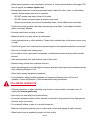
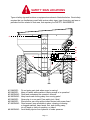
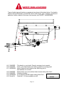
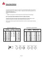
1
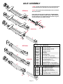
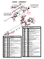
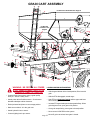
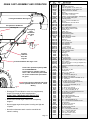
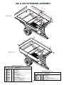
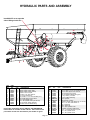
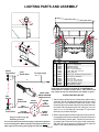
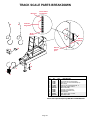
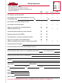
1/07
AG20022 Rev 3
Page 1
Page 2
Table of Contents
General information ................................................................................................. 3
Safety You Can Live With ...................................................................................... 4-10
Safety Sign Locations .......................................................................................... 11-12
Bolt Torque .............................................................................................................. 13
Axle Assembly and Parts Breakdown .................................................................... 14
Track Axle Assembly and Parts Breakdown ........................................................... 15
Auger Assembly and Parts Breakdown .................................................................. 16
Hydraulic Drive Assembly and Parts Breakdown ................................................... 17
Grain Cart Assembly and Parts Breakdown ......................................................... 18-19
950 Bushel Extensions Assembly and Parts Breakdown ....................................... 20
Hydraulics Assembly and Parts Breakdown ........................................................... 21
Lighting Assembly and Parts Breakdown ............................................................... 22
Scale Option and Parts Breakdown ........................................................................ 23
Scale Assembly and Parts Breakdown for Tracks .................................................. 24
Dial Indicator Assembly and Parts Breakdown ....................................................... 25
Door Lift Assembly and Parts Breakdown .............................................................. 26
Window Assembly and Parts Breakdown ............................................................... 26
Maintenance, Grease and Lube .............................................................................. 27
Grain Cart Checklist and Tire inflation .................................................................... 28
Warranty Registration ........................................................................................... 29-30
INTRODUCTION
Thank you for purchasing a Demco Grain Cart. We feel you have made a wise choice and hope you are completely
satisfied with your new piece of equipment. Proper care and use will result in many years of service.
WARNING:
TO AVOID PERSONAL INJURY OR DEATH, OBSERVE FOLLOWING
INSTRUCTIONS:
Ensure that anybody present is clear before applying power to any machinery used in
conjunction with grain cart or when moving grain cart.
Never allow anyone in, near, or on grain cart during transporting or unloading of grain.
Moving grain is dangerous and can cause entrapment, resulting in severe injury or death
by suffocation.
Do not exceed 20 miles per hour when towing grain cart.
GENERAL INFORMATION
1. Unless otherwise specified, high-strength (grade5) (3
radial-line head markings) hex head bolts are used
throughout assembly of this piece of equipment.
3. When placing a parts order, refer to this manual for proper part
numbers and place order by PART NO. and DESCRIPTION.
4.
2. Whenever terms "LEFT" and "RIGHT" are used in this
manual it means from a position behind wagon box and
facing forward.
Page 3
Read assembly instructions carefully. Study assembly
procedures and all illustrations before you begin assembly.
Note which parts are used in each step. This unit must be
assembled in proper sequence or complications will result.
SAFETY
TAKE NOTE! THIS SAFETY ALERT SYMBOL FOUND THROUGHOUT THIS
MANUAL IS USED TO CALL YOUR ATTENTION TO INSTRUCTIONS
INVOLVING YOUR PERSONAL SAFETY AND SAFETY OF OTHERS. FAILURE
TO FOLLOW THESE INSTRUCTIONS CAN RESULT IN INJURY OR DEATH!
THIS SYMBOL MEANS
ATTENTION
BECOME ALERT
YOUR SAFETY IS INVOLVED!
SIGNAL WORDS:
WARNING:
This manual uses of the following signal words-DANGER, WARNING, and CAUTION-- with safety
messages. The appropriate signal word has been
selected using the following guidelines.
Indicates a potentially hazardous situation that, if
not avoided, could result in death or serious injury,
and includes hazards that are exposed when
guards are removed. It may also be used to alert
against unsafe practices.
DANGER:
Indicates an imminently hazardous situation that,
if not avoided, will result in death or serious injury.
This signal word is to be limited to most extreme
situations typically for machine components which,
for functional purposes, cannot be guarded.
CAUTION:
Indicates a potentially hazardous situation that, if
not avoided, may result in minor or moderate injury.
It may also be used to alert against unsafe practices.
If you have questions not answered in this manual, require additional copies, or if your manual is damaged,
please contact your dealer or Dethmers Mfg. Co., P.O. Box 189, 4010 320th Street, Boyden, IA 51234
ph: (712) 725-2311 or Toll Free: 1-800-543-3626 Fax: (712) 725-2380 or 1-800-845-6420
http://www.demco-products.com
Page 4
SAFETY...YOU CAN LIVE WITH IT
EQUIPMENT SAFETY GUIDELINES
Every year many accidents occur which could have been avoided by a few seconds of
thought and a more careful approach to handling equipment. You, the operator, can avoid
many accidents by observing the following precautions in this section. To avoid personal
injury, study the following precautions and insist those working with you, or you yourself,
follow them.
In order to provide a better view, certain illustrations in your owners manual may show an
assembly with a safety shield removed. However, equipment should never be operated in
this condition. Keep all shields in place. If shield removal becomes necessary for repairs,
replace shield prior to use.
Replace any caution, warning, danger or instruction safety decal that is not readable or is
missing.
Do not attempt to operate this equipment under the influence of alcohol or drugs.
Review safety instructions with all users annually.
Operator should be a responsible adult. DO NOT ALLOW PERSONS TO OPERATE OR
ASSEMBLE THIS UNIT UNTIL THEY HAVE DEVELOPED A THOROUGH
UNDERSTANDING OF SAFETY PRECAUTIONS AND HOW IT WORKS.
To prevent injury or death, use a tractor equipped with a roll over protective system (ROPS).
Do not paint over, remove, or deface any safety signs or warning decals on your equipment.
Observe all safety signs and practice instructions on them.
Never exceed limits of a piece of machinery. If its ability to do a job, or to do so safely is in
question DON'T TRY IT.
LIGHTING AND MARKING
It is the responsibility of customer to know lighting and marking requirements of local highway
authorities and to install and maintain equipment to provide compliance with regulations.
Add extra lights when transporting at night or during periods of limited visibility.
Lighting kits are available from your dealer or from manufacturer.
Page 5
SAFETY SIGN CARE
• Keep safety signs clean and legible at all times.
• Replace safety signs that are missing or have become illegible.
• Replacement parts that displayed a safety sign should also display current sign.
• Safety signs are available from your distributor, dealer parts department, or factory.
How to install safety signs:
• Be sure that installation area is clean and dry.
• Decide on exact position before you remove backing paper.
• Remove smallest portion of split backing paper.
• Align decal over specified area and carefully press small portion with exposed sticky
backing in place.
• Slowly peel back remaining paper and carefully smooth remaining portion of decal into
place.
• Small air pockets can be pierced with a pin and smoothed out using piece of decal
backing paper.
TIRE SAFETY
• Failure to follow proper procedures when mounting a tire on a rim can produce an
explosion which may result in a serious injury or death.
• Do not attempt to mount a tire unless you have proper equipment and experience to
do job.
• Inflating or servicing tires can be dangerous. Whenever possible, trained personnel
should be called to service and/or mount tires.
• Always order and install tires and wheels with appropriate type and load capacity to meet
or exceed anticipated weight to be placed on the equipment.
• NEVER exceed 40 psi tire inflation when using truck tires on gravity flow wagons.
• Refer to “TIRE INFLATION CHART” in your owners manual for maxium tire pressure for
a Demco Grain Cart.
REMEMBER
Your best assurance against accidents is a careful and responsible operator. If there is any
portion of this manual or function you do not understand, contact your local authorized dealer
or manufacturer.
Page 6
BEFORE OPERATION:
• Carefully study and understand this manual and the Owner’s Manual.
• Do not wear loose-fitting clothing which may catch in moving parts.
• Always wear protective clothing and substantial shoes.
• It is recommended that suitable protective hearing and eye protection be worn.
• Operator may come in contact with certain materials which may require specific safety
equipment relative to handling of such materials. (Examples: extremely dusty, molds,
fungus, bulk fertilizers, etc.)
• Keep wheel and lug nuts tightened to specified torque.
• Assure that agricultural implement tires are inflated evenly.
• Give unit a visual inspection for any loose bolts, worn parts, or cracked welds, and make
necessary repairs. Follow maintenance safety instructions included in this manual.
• Be sure there are no tools lying on or in equipment
• Do not use unit until you are sure that area is clear, especially around children and animals.
• Don't hurry learning process or take unit for granted. Ease into it and become familiar
with your new equipment.
• Practice operation of your equipment and its attachments. Completely familiarize yourself
and other operators with its operation before using.
• Make sure that brakes are evenly adjusted (if equipped with brakes)
• Use a tractor equipped with Roll Over Protection System (ROPS) and fasten your seat belt
prior to starting the engine.
• Manufacturer does not recommend usage of a tractor with the ROPS removed.
• Move tractor wheels to widest recommended settings to increase stability.
• Do not allow anyone to stand between tongue or hitch and towing vehicle when backing up
to equipment.
DURING OPERATION
• Beware of bystanders, PARTICULARLY CHILDREN! Always look around to make sure that it
is safe to start engine of towing vehicle or move unit. This is particularly important with higher
noise levels and quiet cabs, as you may not hear people shouting.
• NO PASSENGERS ALLOWED- Do not carry passengers anywhere on or in tractor or
equipment.
• Keep hands and clothing clear of moving parts.
• Do not clean, lubricate, or adjust your equipment while it is moving.
Page 7
• When halting operation, even periodically, set tractor or towing vehicles brakes, disengage PTO,
shut off engine, and remove ignition key.
• Be especially observant of operating area and terrain. Watch for holes, rocks, or other hidden
hazards. Always inspect area prior to operation.
-
DO NOT operate near edge of drop-off or banks.
-
DO NOT operate on steep slopes as overturn may result.
-
Operate up and down (not across) intermediate slopes. Avoid sudden starts and stops.
• Pick the most level possible route when transporting across fields. Avoid edges of ditches,
gullies, and steep hillsides.
• Be extra careful when working on inclines.
• Maneuver tractor or towing vehicle at safe speeds.
• Avoid overhead wires or other obstacles. Contact with overhead lines could cause serious injury
or death.
• Avoid loose gravel, rocks, and holes; they can be dangerous for equipment operation or movement.
• Allow for unit length when making turns.
• Do not walk or work under raised components or attachments unless securely positioned and
blocked.
• Keep all bystanders, pets, and livestock clear of work area.
• Operate towing vehicle from operators seat only.
• Never stand alongside of unit with engine running or attempt to start engine and/or operate machine
while standing alongside of unit.
• Never leave running equipment unattended.
• As a precaution, always recheck hardware on equipment following every 100 hours of
operation. Correct all problems. Follow maintenance safety procedures.
FOLLOWING OPERATION
• Following operation, or when unhitching, stop tractor or towing vehicle, set brakes, shut off
engine and remove ignition key.
• Store unit in an area away from human activity.
• Do not park equipment where it will be exposed to livestock for long periods of time. Damage and
livestock injury could result.
• Do not permit children to play on or around stored unit.
• Make sure all parked machines are on a hard, level surface and engage all safety devices.
• Wheel chocks may be needed to prevent unit from rolling.
Page 8
HIGHWAY AND TRANSPORT OPERATIONS
• SAFETY CHAINS: If equipment is going to be transported on a public highway, always
follow state and local regulations regarding safety chains and auxiliary lighting. Be sure
to check with local law enforcement agencies for your own particular regulations.
Only safety chains (not elastic or nylon/plastic tow straps) should be used to retain
connection between towing and towed machines in event of separation of primary attaching
system. Use a high strength, appropriately sized hitch pin with a mechanical retainer and
attach safety chains. Criss cross chains under tongue and secure to draw bar cage,
mounting loops, or bumper frame.
• Adopt safe driving practices:
-
Keep brake pedals latched together at all times. NEVER USE INDEPENDENT BRAKING
WITH MACHINE IN TOW, LOSS OF CONTROL AND/OR UPSET OF UNIT CAN RESULT.
-
Always drive at a safe speed relative to local conditions, ensure that your speed is low
enough for an emergency stop. Keep speed to a minimum.
-
Reduce speed prior to turns to avoid risk of overturning.
-
Always keep tractor or towing vehicle in gear to provide engine braking when going
downhill. Do not coast.
-
Do not drink and drive!
• Comply with state and local laws governing highway safety and movement of farm machinery on
public roads.
• Use approved accessory lighting, flags and necessary warning devices to protect operators of
other vehicles on highway during transport. Various safety lights and devices are available
from your dealer.
• Use of flashing amber lights is acceptable in most localities. However, some localities prohibit
their use. Local laws should be checked for all highway lighting and marking requirements.
• When driving tractor and equipment on road under 20 m.p.h. (40 kph) at night or during day,
use flashing amber warning lights and a slow moving vehicle (SMV) identification emblem.
• Plan your route to avoid heavy traffic.
• Be a safe and courteous driver. Always yield to oncoming traffic in all situations, including narrow
bridges, intersections, etc.
• Be observant of bridge load ratings. Do not cross bridges rated lower than gross weight
at which you are operating.
Page 9
• Watch for obstructions overhead and side to side while transporting.
• Always operate equipment in a position to provide maximum visibility. Make allowances for
increased length and weight of equipment when making turns, stopping unit, etc.
PERFORMING MAINTENANCE
•
Good maintenance is your responsibility. Poor maintenance is an invitation to trouble.
•
Make sure there is plenty of ventilation. Never operate engine of towing vehicle in
a closed building. Exhaust fumes may cause asphyxiation.
•
Before working on this machine, stop towing vehicle, set brakes, shut off engine
and remove ignition key.
•
Always use safety support and block wheels. Never use a jack to support machine.
•
Always use proper tools or equipment for job at hand.
•
Use extreme caution when making adjustments.
•
Follow torque chart in owners manual when tightening bolts and nuts.
•
Never use your hands to locate a hydraulic leak on attachments. Use a small piece of
cardboard or wood. Hydraulic fluid escaping under pressure can penetrate skin.
•
Openings in skin and minor cuts are susceptible to infection from hydraulic fluid.
Without immediate medical treatment, serious infection and reactions can occur.
•
When disconnecting hydraulic lines, shut off hydraulic supply and relieve all hydraulic
pressure.
•
Replace all shields and guards after servicing and before moving.
•
After servicing, be sure all tools, parts and service equipment are removed.
•
Do not allow grease or oil to build up on any steps or platform.
•
When replacing bolts, refer to owners manual.
•
Refer to bolt torque chart in owners manual for head identification marking.
•
Where replacement parts are necessary for periodic maintenance and servicing,
genuine factory replacement parts must be used to restore your equipment to original
specifications. Manufacturer will not claim responsibility for use of unapproved parts
or accessories and other damages as a result of their use.
•
If equipment has been altered in any way from original design, manufacturer does
not accept any liability for injury or warranty.
•
A fire extinguisher and first aid kit should be kept readily accessible while performing
maintenance on this equipment
Page 10
SAFETY SIGN LOCATIONS
Types of safety sign and locations on equipment are shown in illustration below. Good safety
requires that you familiarize yourself with various safety signs, type of warning, and area or
particular function related to that area, that requires your SAFETY AWARENESS.
#1
#2
#6
#5
#7
#3
#4
#14
#8
#1 DANGER #2 DANGER #3 WARNING #4 WARNING #5 DANGER #6 DANGER #7 WARNING -
Do not enter grain tank when auger is running!
Keep off ladder while machine is being moved or in operation!
Read and understand the operator’s manual!
Keep hands and clothing away from moving parts!
Never play in or on grain! Farm safety just 4 kids!
Electrocution can occur without direct contact with power lines !
Read manual, keep all shields in place, cleaning or clearing
a clogged machine, keep hands, feet, and clothing away,
do not stand or climb on machine, no riders!
#8 WARNING - Avoid bodily injuries from hydraulic oil under pressure.
Page 11
SAFETY SIGN LOCATIONS
Types of safety sign and locations on equipment are shown in illustration below. Good safety
requires that you familiarize yourself with various safety signs, type of warning, and area or
particular function related to that area, that requires your SAFETY AWARENESS.
#11
#10
#9
#12
#13
# 9 DANGER - This decal is on pto shaft, Guard is missing do not operate!
#10 DANGER - Pinch- point keep hands and clothing away from moving parts!
#11 WARNING - Keep all persons and objects clear while any part of
this machine is in motion!
#12 DANGER - Electrocution can occur without direct contact with power lines!
#13 DANGER - Rotating driveline!
Decal order number
#14 WARNING - Do not exceed 20 MPH when towing Grain Cart
#15 Decal KitDecals #1 - #14 are available as a kit.
AG21064
Page 12
Torque Specifications
Torque figures indicated are valid for non-greased or non-oiled threads and heads unless otherwise
specified. Therefore, do not grease or oil bolts or capscrews unless otherwise specified in this
manual. When using locking
elements, increase torque values
by 5%.
* GRADE or CLASS value for bolts and capscrews are identified by their head markings.
BOLT TORQUE DATA FOR STANDARD NUTS, BOLTS, AND CAPSCREWS.
Tighten all bolts to torques specified in chart unless otherwise noted. Check tightness of bolts
periodically, using bolt chart as guide. Replace hardware with same grade bolt.
NOTE: Unless otherwise specified, high-strength Grade 5 hex bolts are used throughout assembly
of equipment.
Bolt Torque for Metric bolts *
“A”
6
7
8
10
12
14
16
18
20
22
24
CLASS 8.8
lb-ft (N.m)
9
(13)
15
(21)
23
(31)
45
(61)
78
(106)
125 (169)
194 (263)
268 (363)
378 (513)
516 (699)
654 (886)
Bolt Torque for Standard bolts *
CLASS 9.8 CLASS 10.9
lb-ft (N.m) lb-ft (N.m)
10
(14)
13
(17)
18
(24)
21
(29)
25
(34)
31
(42)
50
(68)
61
(83)
88
(118)
106 (144)
140
(189)
170 (230)
216
(293)
263 (357)
--364
(493)
--515
(689)
--702
(952)
--890 (1206)
GRADE-2
“A”
1/4”
5/16”
3/8”
7/16”
1/2”
9/16”
5/8”
3/4”
7/8”
1”
GRADE-5
GRADE-8
GRADE 2
lb-ft (N.m) lb-ft
6
10
20
30
45
70
95
165
170
225
(8)
(13)
(27)
(40)
(60)
(95)
(130)
(225)
(230)
(300)
(12)
(25)
(40)
(70)
(100)
(155)
(200)
(390)
(570)
(850)
12 (16)
25 (35)
45 (60)
80 (110)
115 (155)
165 (220)
225 (300)
400 (540)
650 (880)
970 -(1310)
CLASS 8.8 CLASS 9.8 CLASS 10.9
8.8
Page 13
9
18
30
50
75
115
150
290
420
630
GRADE 5 GRADE 8
(N.m) lb-ft (N.m)
9.8
10.9
AXLE ASSEMBLY
* NOTE: The 3/4” stud must be driven out and replaced with the
1” stud when duals are mounted on the hub of the grain cart
NOTE: The long fixed axle (item #2 & #2a) must be used with
dual rims and tires.
950 Axles
1
Please order replacement parts by PART NO. and DESCRIPTION.
Painted Parts are available in Red or Green. Add -10 behind
the part number for red, -20 behind the part number for green,
and -30 behind the part number for black.
9
8
2
15
6
19
18
23
20
16
3
*Duals Only
17
14
13
12
22
21
10
4
11
7
1a
800 Axles
2a
*Duals Only
3a
7a
REF.
NO.
1.
1a.
2.
2a.
3.
3a.
4.
6.
7.
7a.
8.
9.
10.
11.
12.
13.
14.
15.
*16.
17.
18.
19.
20.
21.
22.
23.
-
4
Page 14
PART
NO.
QTY. DESCRIPTION
11174-30 1
Fixed 120” Axle (950)
09668-30 1
Fixed 120” Axle (800)
11428-30 1
Fixed Axle for Duals only (950)
11580-30 1
Fixed Axle for Duals only (800)
11175-30 1
Adjustable Axle (950)
09684-30 1
Adjustable Axle (800)
09206-30 2
Axle Insert
09204
2
Axle Spindle
11712-30 2
Axle Clamps (950)
09214-30 2
Axle Clamps (800)
04836
2
5/8”-11 UNC x 7” Hex Head Bolt
02587
2
5/8-11 UNC Nylon Insert Locknut
11613
8
1/2”-13 UNC x 2-1/2” Hex Head Bolt (Gr. 8)
02178
8
1/2”-13 Nylon Insert Locknut
09445
1
2”-12 UNF Castle Nut
09444
1
2-1/16” ID x 4” OD x 1/4” Washer
09446
1
3/8” x 3” Cotter Pin
07861
Replacement 3/4”NF x 2-3/4” Stud Bolt
10827
Replacement 1”NF x 4” Stud (Duals ONLY)
11295
Replacement 3/4”NF x 2-3/4” Stud (35.5 x 32 only)
5540
2
Hub Assembly(Includes items16-22)
09448
1
Outer Bearing Race (HM212011)
09450
1
Outer Bearing (HM 212049)
09449
1
Inner Bearing (HM 218248)
09452
1
Inner Grease Seal (CR43771)
09447
1
Inner Bearing Race (HM218210)
09451
1
Dust Cap
04305
4
5/16-18 UNC x 1/2” Hex Head Bolt (Gr.5)
07435
20
3/4”-16 UNF Lug Nut
---20
1”-16UNF Lug Nut w/ washer (Incl.with10827 stud bolt)
TRACK AXLE ASSEMBLY
6
2
10
1
7
10
7
7
2
2
10
11
3
7
9
6
2
REF. PART
NO.
NO.
QTY.
1. 12270-30 1
2.
10939-30 4
3.
10940
4
4.
5.
6.
12269
2
7.
00254
24
8.
9.
11097
16
10.
11098
24
11.
11099
8
11
DESCRIPTION
Track Axle Assembly (RWF Bron)
Axle Mounting Plates
Weigh Bar
Rubber Track (STX Quad Goodyear)
1/2” Spring Lockwasher
3/4”NC X 2.00” Hex Head Bolt (Gr. 8)
3/4”NC Hex Nut (Gr. 8)
3/4”NC X 5.00” Hex Head Bolt (Gr. 8)
Please order replacement parts by PART NO. and DESCRIPTION.
* NOTE: Refer to RWF Bron® owner/parts manual for proper
maintenence and operation of the tracks on this grain cart.
Page 15
AUGER ASSEMBLY
29
36
30
35
35
28
25
34
32 38
31 33
40
29
30
38
38
26
12
15
18
7
27
23
19 17
21
20
24
25
42
REF.
NO.
1.
2.
3.
4.
5.
6.
7.
8.
9.
10.
11.
12.
13.
14.
15.
16.
17.
18.
19.
20.
21.
22.
23.
24.
25.
26.
27.
28.
29.
43
11
10
10
54
53
10 54
52
53 51
66 67 46
52
67 65
50
66
37
49
47
25
58
45
59
62
16
48
61
25
60
70
6 67 65 67
64
65
4
5
57
63 59
3 25
56
8
16
55
1
44
63
59
18
9
Lower auger
shown here
for clarity
14
22
2
10
11
13
14
NOTE: Be sure to check
and lubricate the slide gate
guide rods when doing the
maintenance on page 19.
NOTE: Be sure to check
and lubricate the inner gate
when doing the maintenance on page 27 or every
20 hours.
38
31
41
38
PART
NO.
QTY.
DESCRIPTION
12517-?
1 Outer Auger Tube (-10 for red, -20 for green)
12432-30
1 Outer Auger Flighting
10634
1 Flange Bearing
09168
4 Upper Auger Spring
01922
1 1-1/2”-12 UNF Hex Nut w/ Set Screw Hole
01923
1 1/4” Socket Hd. Cup Point Set Screw x 1/4”
00789
1 3/8”-16 UNC x 3/8” Socket Head Set Screw
01975
4 1/2”NC x 5” Hex Head Bolt (Gr. 5)
10607
1 Gear Box
01254
15 1/2”-13 UNC x 1-1/2” Hex Head Bolt (Gr.5)
00084
4 1/2” Lockwasher
10623-30
1 Lower Drive
10613-30
1 Lower Auger Flighting
09203
2 Slide Rod
00523
2 3/8”-16 UNC x 1-1/4” Hex Head Bolt (Gr.5)
02592
10 3/8”-16 Nylon Insert Locknut
11099
1 3/4”-10 UNC x 5” Hex Head Nut (Gr.8)
02961
2 3/4”-10 UNC Nylon Insert Locknut
09185
1 2” Hanger Bearing
00482
2 1/2”-13 UNC x 1 3/4” Hex Head Bolt (Gr.5)
09195-30
1 Hanger Bearing Mount
10624-30
1 Hanger Bearing Plate
07412
1 1 1/4”-12 UNF Jam Nut
00085
6 1/2” Flatwasher
02178
16 1/2”-13 UNC Nylon Insert Locknut
12233-30
1 Male Auger Connection
10604-30
1 Gauge Rod
12537-30
1 Inner Door
03738-95
2 1” Dia x 3” Cylinder Pin
REF.
NO.
30.
31.
32.
33.
34.
35.
36.
37.
38.
39.
40.
41.
42.
43.
44.
45.
46.
47.
48.
49.
50.
51.
52.
53.
54.
55.
56.
57.
58.
59.
60.
61.
62.
63.
64.
65.
66.
67.
68.
69.
70.
Page 16
PART
NO.
QTY.
DESCRIPTION
00116
4 5/32” x 1-1/2” Cotter Pin
05195
2 Straight Hyd. Ftg. 3/8” MPT x 3/8” JIC
09930-30
1 2-1/2” Cylinder x 30” Stroke
5584
Hydraulic Cylinder Seal Repair Kit (not shown)
00083
1 1/2”-13 UNC Hex Head Nut
05191
1 36” Hydraulic Hose
09172
2 3/8” JIC Bulkhead 45° Elbow Ftg. W/Nut
09741-30
1 Adjustable Cylinder Clevis End
12516-30
1 Discharge Chute Drive Ring
04642
5 Grease Zerk
05215
05190
12028
10525
09218-95
12393
12394
12515-30
12522-30
12513-30
12514-95
12512-30
09283
09282
12531-95
01253
09437
12555-30
05290
01899
12549-30
12550
12667-95
00060
00908
02990
02802
07872
12528
12529
00482
1
1
1
1
7
1
1
1
1
1
1
1
5
5
5
2
1
1
1
15
4
4
8
9
8
20
20
30
1
1
1
3/8” MPT x 3/8” FPT Hyd. Elbow Fitting
48” Hydraulic Hose
Outer Drive Casting
3/4”-10 UNC x 6” Hex Head Bolt Gr. 8
Hose Keeper, 2 Hose (plated)
Discharge Chute, left half
Discharge Chute, right half
Cylinder mount
Cylinder
Trolley Bottom
Trolley Spacer
Trolley Top
Sheave Bushing
Plastic Sheave
Cable Retainer Washer
1/2”-13UNC x 2” Hex Head Bolt (Gr.5)
Discharge Light
Light Bracket
1/2”-13UNC x 3 1/4” Hex Head Bolt (Gr.5)
3/8”-16UNC x 3/4” Hex Head Bolt (Gr.5)
Mount Ring Retainer Backplate
Plastic Mount Ring Spacer
Mount Ring Bushing
3/8” Lockwasher
3/8”-16 UNC x 1 3/4” Hex Head Bolt (Gr.5)
5/16”-18UNC x 1” Hex Head Bolt (Gr.5)
5/16”-18UNC Nylon Locknut
5/16” Flatwasher
Long Cable (pg. 17)
Short Cable (pg. 17)
1/2”-13UNC x 1 3/4” Hex Head Bolt (Gr.5)
ADJUSTABLE AUGER CABLE ROUTING
69
68
HYDRAULIC DRIVE ASSEMBLY
3
12
7
9
8
10
6
5
2
4
13
11
1
NOTE: IN ORDER TO MOUNT PLATE #9;
FOUR .56 DIA. HOLES WILL NEED TO BE
DRILLED THROUGH THE BEARING PLATE AS
SHOWN IF HOLES ARE NOT PRESENT
Operation
• Make sure the hydraulic motor is connected to
the tractor’s priority port.
• The hydraulic return line should free-dump
directly into the reservoir.
REF. PART
NO.
NO.
1.
05197
2.
11219
3.
02178
4.
11225
5.
11217
6.
05256
7.
00967
8.
01253
9.
11221-30
10.
11218
11.
05198
12.
11220
13.
11216
QTY.
2
2
8
2
1
2
4
4
1
1
2
1
2
DESCRIPTION
Quick Coupler (1/2” FPT with male tip)
Hydraulic Hose
1/2”-13 UNC Nylon Insert Locknut
Hydraulic O-Ring Fitting (Pump to Hose)
Hydraulic Motor
3/8”NC X .50” Socket Head Set Screw
1/2”-13 UNC x 1.25” Bolt Gr.5)
1/2”-13 UNC x 2.00” Bolt (Gr.5)
Hyd. Motor Mounting Plate
Universal Joint with Clutch
Rubber Quick Coupler Cover
Drive Shaft For Hyd. Drive
Adapter Union (.50 MPT X .75 FPT)
Please order replacement parts by PART NO. and DESCRIPTION.
Page 17
GRAIN CART ASSEMBLY
1
2
1
For Extension Breakdown See Page 20
47
46
4
For Window
Installation See
Page26
33
44
47
31
32
34
44 31
5
58
63
23
8
64
28
57
21
74
76
74
29
27
47
22
24
64 66
59
7
30
45
46
47
48
55
39
12
57
60
61,62
17
25
45
3
53
44
20
46
8
35
26
6
39
47
11
52
9
13
69
51
49
50
15
12
38
69
16
75
53 75
54
14
53
17
43
• Connect Grain Cart to tractor using a good quaility
hitch pin. Attach a safety chain.
• Attach power take-off shaft to tractor. Check tractor
drawbar and adjust to allow clearance.
• Raise jack stand and place to rear storage position.
• Make sure no debris is in the grain cart.
• Attach hydraulic lines to tractor.
• Connect lighting hook-up to tractor.
55
54 55
WARNING: BE CERTAIN ALL POWER
IS OFF WHEN CONNECTING PTO OR
HYDRAULIC LINES TO TRACTOR
For Dial Indicator
Installation See
Page 25
18
17
16
19
53
54
55
54 55
58
56
67
LOADING AND UNLOADING GRAIN
• With the gate indicator in the closed position, fill the box with
grain.
• With the PTO disengaged, extend auger.
• Start PTO at a slow rate of speed until the upper and lower
drives are engaged.
• Increase PTO speed and open the inner gate halfway. When
grain begins to flow, open gate to full position.
• Once grain stops flowing, return gate to closed position.
• Never exceed 1000 RPM on the system.
• Never fill grain cart unless inner gate is closed.
Page 18
GRAIN CART ASSEMBLY AND OPERATION
For Auger Breakdown See Page 16
For Hydraulics Breakdown
See Page 21
For Lighting
Parts
Breakdown
See Page
22
35
37
68
41
70
10
59
72
64
73
36
For Door
Lift Breakdown See
Page 26
For Axle Breakdown See Pages 14-15
Please order replacement parts by PART
NO. and DESCRIPTION.
Painted Parts are available in Red or
Green. Add -10 behind the part number
for red and -20 behind the part number
for green.
40
42
NOTE: Torque lugnuts to 500 ft/lbs and inflate
tires to specified amount on the tire. Check
Weekly.
• Disengage PTO and allow it to come to a complete stop.
Auger is now ready to fold to stored position.
DO NOT PULL THE GRAIN CART UNLESS THE
AUGER IS IN THE STORED POSITION.
• Never fold or extend auger unless PTO is completely
stopped.
• Never engage auger when system is moving at a high rate
of speed.
• Never do maintenance work or service cart while the
tractor is running.
Page 19
REF.
NO.
1.
2.
3.
4.
5.
6.
7.
8.
9.
10.
11.
12.
13.
14.
15.
16.
17.
18.
19.
20.
21.
22.
23.
24.
25.
26.
27.
28.
29.
30.
31.
32.
33.
34.
35.
36.
37.
--.
38.
39.
40.
--.
--.
--.
--.
--.
41.
42.
43.
44.
45.
46.
47.
48.
49.
50.
51.
52.
53.
54.
55.
56.
57.
58.
59.
60.
61.
62.
63.
64.
65.
66.
67.
68.
69.
70.
72.
73.
74.
75.
76.
PART
NO.
QTY.
DESCRIPTION
03159
2 Square Cap Plug
10621-30
1 Ladder
10609-30
1 PTO Shaft Guard Step
12540-?
1 Undercarriage/Box for 950 Grain Cart
12539-?
1 Undercarriage/Box for 800 Grain Cart
07310
2 Rubber Grommet for Window
07276
2 Window
10612
1 Drive Shaft for 950 BU Grain Cart
10622
2 5/16” x 5/16” x 2-3/4” Key
12350-30
1 Category 4 Forged Hitch Base, Austempered
07594
2 3/8” x 1” THread Cutting Bolt
12346-30
1 Pintle Ring Mount
11698
2 7/8” x 5 1/2” Hex Head Bolt Gr. 8
10814
1 Hitch Pin
09219-30
1 7000# Sidewind Jack with Mount
10610-30
1 Front Safety Shield
10611-30
2 Rear Safety Shield
10633
3 35mm 4-Bolt Flange Bearing
10617-30
1 Bearing Mount for Drive Shaft
10615
1 Universal Joint
10658-30
1 Pointer Assy.
10659-30
1 Dial Indicator Plate
10660-30
1 Pointer Mounting Plate
10661-30
1 Pointer Brkt Assy.
10673
2 Tension Spring for Pointer
10080
1 Cable For Pointer
10631-30
1 Folding Pin
10637-30
1 Door Lift Channel
10620-30
1 Lower Outside Door
10629-30
1 Door Lift Wheel
11525-30
1 Door Lift Mount
03738-95
2 1” x 3” Cylinder pin
09930-30
1 Hydraulic Cylinder
09741-30
1 Adjustable Cylinder End
09198-30
1 Folding Cylinder Mount
07412
2 1-1/4” Jam Nut
12126
1 SMV Sign
10032
1 Left Ag Light
10033
1 Right Ag Light
12375-30
1 Hitch Stop Collar
61681
7 1” Anti-Skid Tape
9445208
2 Single Wheel (30.5L x 32 24 ply Tire)(Rim Incl.)
10401-56
2 VA27 x 32 Rim
9445204
2 Single Wheel (30.5L x 32 12 ply Tire)(Rim Incl.)
09381-56
2 DW27A x 32 Rim
-2 Dual Wheel (520/85R-38 Tire)(Rims Incl.)
10830
4 Dual Rim
11565-30
2 Light Mount
07435
20 3/4”-16 UNF Lug Nut
10816-30
1 Bearing Mount
00116
5 5/32” x 1-1/2” Cotter Pin
00059
12 3/8” Flatwasher
00523
6 3/8” x 1-1/4” Hex Bolt (Gr. 5)
02592
27 3/8” Nylon Insert Locknut
05047
16 3/4”-10UNC x 2-1/2”Hex Head Bolt (Gr. 5)
00492
16 3/4” Flatwasher
02961
16 3/4”-10UNC Nylon Insert Locknut
09454
2 1”-14 UNF x 6-1/2” Hex Head Bolt (Gr. 8)
09455
2 1” -14 UNF Stover Locknut
01254
18 1/2” x 1-1/2” Hex Head Bolt (Gr. 5)
00085
20 1/2” Flatwasher
02178
18 1/2” Nylon Insert Locknut
05103
1 5/8” x 3-1/2” Hex Head Bolt (Gr. 5)
00907
22 3/8” x 1” Hex Head Bolt (Gr. 5)
05256
4 3/8”-16 UNC x 1/2” Socket Head Set Screw
02772
4 1/4” Nylon Insert Locknut
10277
1 Electrical Plug Holder
10241
1 Owner’s Manual Cannister
10242
1 Owner’s Manual Cannister Bracket
11862
1 1-3/4” PTO Shaft
04055
4 1/4” x 1” Hex Head Bolt (Gr. 5)
00639
8 1/2” x 1-1/2” Set Screw w/00640 Jam Nut
00214
2 1/4” Flatwasher
02587
1 5/8” Nylon Insert Locknut
11568-30
2 Light Mount Reciever
10678
2 7/8” Nylon Insert Locknut
12468-30
1 SMV Sign Bracket
00639
4 1/2” x 1 1/2” Square Head Bolt
00209
4 3/8” x 1” Square Head Bolt
02990
14 5/16” x 1” Hex Head Bolt
02802
14 5/16” Nylon Insert Locknut
00004
22 5/16” Flatwasher
800 & 950 EXTENSION ASSEMBLY
3
11
2
12
9
6
5
13
10
11
950 Grain Cart
5
8
12
9 7
4
3
5
9
8
976
8
1
8
4
18
17
15
19
16
18
17
19
19
800 Grain Cart
18
14
950 Extension Parts List
REF.
NO.
1.
2.
3.
4.
5.
6.
7.
8.
9.
10.
11.
12.
13.
PART
NO.
QTY.
DESCRIPTION
10625-30
1 Front Extension
10630-30
1 Rear Extension
10626-30
2 Left Extension
10627-30
2 Right Extension
10758
8 Side Hinge
10759
4 Front & Rear Hinge
00004
80 5/16” Flatwasher
01263
92 5/16” x 3/4” Hex Hd. Bolt Gr. 5
02802
98 5/16” Locknut
10668-30
1 Cross Angle Brace
00907
2 3/8” X 1” Hex Head Bolt (Gr. 5)
02592
2 3/8” Nylon Insert Locknut
02990
6 5/16” x 1” Hex Head Bolt Gr. 5
800 Extension Parts List
REF. PART
NO.
NO.
QTY.
DESCRIPTION
14. 11510-30
1 Front Extension
15. 11511-30
1 Rear Extension
16. 11512-30
1 Left Extension
17.
00004
16 5/16” Flatwasher
18.
01263
20 5/16” x 3/4” Hex Hd. Bolt Gr. 5
19.
02802
20 5/16” Locknut
Please order replacement parts by PART NO. and DESCRIPTION.
Page 20
HYDRAULIC PARTS AND ASSEMBLY
Item #8 & #27 are on opposite
side of fittings inside box
24
24 25
23
26
18
15
16
22 17
10
13
1 2 3
7
5
11
6
REF.
NO.
1.
2.
3.
4.
5.
6.
7.
8.
9.
10.
PART
NO.
05198
12677
12678
05197
05831
05840
00914
02592
09171
05191
03743
05215
QTY.
2
2
2
6
6
2
3
3
4
1
2
2
5
11
14
17
6
19
12
7
9
19
21
20
10
4
5
6
DESCRIPTION
Rubber Coupler Cover (Black)
Rubber Coupler Cover (Red)
Rubber Coupler Cover (Yellow)
Hydraulic Quick Coupler
1/2” MPT x 3/8” FPT Reducer
1/4” x 84” Hydraulic Hose
3/8”-16 UNC x 1-1/2” Hex Head Bolt (Gr.5)
3/8”-16 UNC Nylon Insert Locknut
1/4” x 16’ Hydraulic Hose
1/4” x 36” Hydraulic Hose (Not Shown)
.041” Hydraulic Swivel Restrictor
3/8” MPT x 3/8” FPT Elbow Fitting
Please order replacement parts by PART NO. and DESCRIPTION.
Painted Parts are available in Red or Green. Add -10 behind the
part number for red and -20 behind the part number for green.
Page 21
REF. PART
NO.
NO.
QTY.
DESCRIPTION
11. 09217-30
2 Hose Keeper (4 Hose)
12.
03547
1 5/16”-18 UNC X 2-1/4” Hex Head Bolt (Gr.5)
13.
07732
1 5/16”-18 UNC Nylon Insert Locknut
14.
07582
1 Pilot Operated Check Valve
15.
12374
2 3/8” JIC Bulkhead Elbow Fitting (45°)
16.
05195
2 Str. Hyd. Fitting, .375 MPT
17.
05243
4 Str. Hyd. Fitting W/O-Ring
18. 09930-30
1 2-1/2” Cylinder
19. 09218-95
3 Hose Keeper (2 Hose)
5584
Hydraulic Cylinder Seal Repair Kit (not shown)
20.
00523
2 3/8” x 1 1/4” Hex Head Bolt Gr. 5
21.
00060
2 3/8” Lockwasher
22.
09950
2 Union, .563 M 2x
23.
12556
2 1/4” x 420” Hydraulic Hose
24.
11143
2 90° Elbow, 6 O-Ring x Male 6 JIC
25. 12522-30
1 1 1/5” x 8” Stroke Hydraulic Cylinder
26.
05192
2 1/4” x 60” Hydraulic Hose
27.
05190
1 1/4” x 48” Hydraulic Hose
LIGHTING PARTS AND ASSEMBLY
7
10 9
2
4
1
1
13
11
3
13
11
11
11
12
REF.
NO.
1.
2.
3.
--.
4.
5.
6.
*7.
8.
9.
10.
11.
12.
13.
--.
12
Amber
Turn/Flasher
(Left)
Yellow Band
To Auger Light
6
GRAIN CART
WIRING DIAGRAM
FRONT OF PLUG
(Right)
Green Band
WHITE
(GROUND)
RED
(AUGER LIGHT)
Amber
Turn/Flasher
BROWN
OR
BLACK
(TAILLIGHT)
GREEN
(RIGHT
BLINKER)
YELLOW
(LEFT BLINKER)
Plug pin location may vary
depending on tractor.
QTY.
2
1
1
1
1
1
1
1
00036
00007
00336
00062
04508
04804
2
2
8
8
4
4
DESCRIPTION
Conspicuity Tape
5/16” x 1” Carriage Bolt
Left Dual Ag Light
Right Dual Ag Light
5/16 x 2” Hex Head Bolt
7-Way Male Plug Connector
Wiring Harness
Auger Light Kit W/Two Prong Connector
5/16” Spring Lockwasher
5/16” Hex Nut
1/4” 1-1/4” Hex Head Bolt
1/4” Nylon Insert Locknut
Amber Reflective Sticker
Red Reflective Sticker
*#7 (09437) includes item #’s 2,4, & 9 along with the light and mount
Please order replacement part by PART NO. and DESCRIPTION.
Painted Parts are available in Red or Green. Add -10 behind the
part number for red and -20 behind the part number for green.
5
Red
Marker
PART
NO.
07278
06925
10032
10033
02103
07416
10608
09437
HOT
INSTALLING THE LIGHT KIT
1. Start wiring the lights as shown in the drawing and the wiring
schematic. Secure the Light Harness (#6) to the frame using
nylon hose ties. Next Attach the lights to the fenders. With
the amber light to the outside of the grain cart and the side with
the amber and red light facing the rear of the grain cart, use
eight 1/4” x 1-1/4” hex bolts (#11) and eight 1/4” nylon insert
locknuts (#12) to attach the lights.
2. When connecting the wire harness (#6) to the front (male tractor) plug (#5) follow the wire schematic as follows: Brown wire
to the Red braking marker lights, Yellow wire to the left turning marker light, Green wire to the right turning marker light,
and White wire to the ground. Proceed wiring the lights as
shown in the drawing and the wiring schematic.
NOTE: Connect the wires to the tractor plug in, make sure all lights are
in correct working order. When working correctly behind a tractor, the
amber lights are the flashing warning lights and the turn signals.
Page 22
SCALE OPTION PARTS BREAKDOWN
From the
Weighbars
To the
Tractor
11
Front View of
Junction Box
For Parts Breakdown of all other Hub
and axle parts see page 14.
1
2
8
12
3
9
10
5
5
4
13
6
7
6
REF. PART
NO.
NO.
QTY.
DESCRIPTION
1.
09410
2 Spindle Insert
2.
12260
2 Spindle with 21’ Wire Harness
3.
09442
2 Grease Seal
4.
12263
1 Hitch Scale with 10’ Wire Harness
5.
11698
2 7/8” x 5 1/2” Hex Head Bolt Gr. 8
6.
10678
2 7/8” Nylon Insert Locknut
7. 10813-30
1 Hitch Assembly
8.
09441
1 8’ Power Cord Harness
9.
12258
1 640M Scale Monitor
12259
1 640M Scale Monitor w/ printer port
10.
09440
1 640M Scale Bracket
11.
12257
1 Junction Box for 640M Scale unit
12.
12264
1 25’ Junction Box to Console Harness (640M)
13. 12375-30
1 Hitch Stop Collar (Black)
Please order replacement parts by PART NO. and DESCRIPTION.
Painted Parts are available in Red or Green. Add -10 behind the
part number for red and -20 behind the part number for green.
Page 23
TRACK SCALE PARTS BREAKDOWN
Not used
2
8
Front view of
junction box
From the
weigh bars
11
To the
tractor
11
1
3
Hole for
gauge
3
Hole for
charge
port
10
9
5
5
12
4
6
7
6
REF. PART
NO.
NO.
QTY.
DESCRIPTION
1.
10941
1 Junction Box
2.
10942
1 8’ Junction Box to Tractor Cable
3.
01263
2 5/16” NC X .75” Hex Head Bolt (Gr. 5)
4.
10806
1 Hitch Scale
5.
11698
2 7/8” x 5 1/2” Hex Head Bolt Gr. 8
6.
10678
2 7/8” Nylon Insert Locknut
7. 12346-30
1 Hitch Assembly
8.
09441
1 8’ Power Cord Harness
9.
10943
1 Scale Monitor (Model 615)
10.
09440
1 Scale Bracket
11.
02802
2 5/16” Nylon Insert Locknut
12. 12375-30
1 Hitch Stop Collar
Please order replacement parts by PART NO. and DESCRIPTION.
Page 24
FOLDING AUGER DIAL INDICATOR PARTS BREAKDOWN
12
15
16
13
9
11
14
7
To the auger
10
9
6
11
10
3
5
8
1
4
11
17
2
7
8
REF.
NO.
1.
2.
3.
4.
5.
6.
7.
8.
9.
10.
11.
12.
13.
14.
15.
16.
17.
PART
NO.
10658-30
10659-30
10660-30
10661-30
10673
00116
10080
04054
02772
03267
10466
11010
10667-30
00914
02592
00059
04633
QTY.
1
1
1
1
2
1
1
2
3
2
4
1
1
1
1
1
7
DESCRIPTION
Pointer Assembly
Dial Indicator Plate
Pointer Mounting Plate
Pointer Bracket
Tension Spring
5/32” x 1-1/2” Cotter Pin
Cable For Pointer
1/4”-NC X 3/4” Slotted Round Head Bolt
1/4” Nylon Insert Locknut
#10-32 Hex Nut
5/16”-NF Hex Nut
Cable End Bolt
Cable Mount For Auger
3/8”-NC X 1.50” Hex Head Bolt (Gr. 5)
3/8” Nylon Insert Locknut
3/8” Flatwasher
3/8” Flatwasher (stainless steel)
Please order replacement parts by PART NO. and DESCRIPTION.
Page 25
WINDOW INSTALLATION
Locking Tab in
Closed Position
INSTALLATION PROCEDURE
The installation must be done from inside
the box.
Window
Inside of Box
1. Place rubber molding in opening. Seam
should begin on side of opening.
Gravity Box
Locking Tab
2. Remove the protective sheeting from both
sides of the plastic window.
3. Slide window into groove in molding. Use a
flat blade screwdriver to get molding seated
correctly. Using soapy water will aid in installation
Window
Inside of Box
4. Using the flat blade screwdriver, press in the
locking tab.
Rubber Seal
Grain Cart
Side
OUTER DOOR LIFT ASSEMBLY
3
20
1
24
18
6
13
4
10
25
26
5
11
12
1
1
9
9
25
9
10
2
7
23
8
21
22
22
14
15
Refer to 5729 when
ordering a new door
opener
18
REF. PART
NO.
NO.
QTY.
DESCRIPTION
1.
00059
2 3/8” Flatwasher
2.
00789
1 3/8” x 3/8” Set Screw
3.
00907
1 3/8” x 1 Hex Bolt (Gr.5)
4.
01113
1 Washer 2 OD x 3/8” ID
5. 01243-30
1 Roller Brace Bracket
6.
01332
1 Sprocket 50B9
7.
02026
1 20 Tooth Sprocket
8.
02028
1 10 Tooth Sprocket
9.
02592
3 3/8” Locknut
10.
02849
2 5/16” x 1-13/8” Roll Pin
11.
05363
1 Bushing 3/4”OD x 3/8”ID x 1-11/16” long
12.
05364
1 Bushing 1-1/4” x 3/4”ID x 1-5/8” long
13. 11525-30
1 Door Lift Mount
14. 10629-30
1 Door Lift Wheel
15. 10637-30
1 Door Lift Channel
16. 10620-30
1 Lower Door
17.
10644
1 Roller Chain (Not Shown)
18.
00523
2 3/8” x 1-1/4” Hex Bolt (Gr.5)
19.
04642
2 Grease Zerk (Not Shown)
20.
02166
1 3/8” x 2 3/4” Hex Bolt (Gr.5)
21.
02534
5 .75 Washer
22.
03096
2 1/4” x 1 1/4” Roll Pin
23.
10632
1 Shaft
24.
11412
1 Latch
25.
00004
2 5/16” Flatwasher
26.
11414
1 Bushing
INSTALLATION PROCEDURE
1. Start by attaching the lower door (#16) to the lift channel
(#15) using two 3/8” x 1-1/4” bolts (#18) and two 3/8”
nylon insert locknuts (#9). Leave bolts loose at this time.
9
16
2. Next assemble the door lift mount (#13) as shown.
Leave the bolts loose at this time. After this is assembled, slide the lower door and lift channel into place
on the grain cart. Slide the assembled lift mount over the
lift channel and bolt into place using two 3/8” x 1-1/4”
bolts (#18), two 3/8” flatwashers (#1), and two 3/8”
locknuts (#9). Now tighten all the bolts.
Page 26
GREASE & LUBE
13 - Inside The Box
11
10
9
1
2
3
8
12
4
6
7
5
Reference numbers #1 -#3 -#6 Are U-Joints -- Check and grease regularly.
Reference number #2 - Is a Telescoping P.T.O. Shaft with two slots in housing -- Fully extend P.T.O. Shaft,
then place one or two pumps of grease in each slot.
Reference numbers #4 -#5 Are fixed self centering sealed bearings -- Do not over grease sealed bearings.
Reference number #7 - Auger gear box is filled with 80-90 gear lube -- To check gear box find inspection allen
plug. Turn out plug. Gear lube should just start to run out. If low fill until gear lube just starts to run out.
Should be about 24-26 oz. of 80-90 gear lube. DO NOT OVER FILL!!! When gear box is full be sure to replace
inspection plug.
Reference number #8 - Is a bushing for the turn handle of the door lift assembly -- Inspect and grease as
needed.
Reference numbers #9 - #11 - Are fixed sealed bearings -- Do not over grease sealed bearings.
Reference number
grease as needed.
#
10 - Is the hinge for the outer tube. There are two zerks in this area -- Inspect and
Reference number #12 - Is the axle hub with inner and outer bearings and races -- Inspect regularly, pack
bearing and replace inner wheel seal as needed.
Reference number #13 - Is four bushings on the inner door. There are four grease zerks on this door--Inspect
and grease every 20 hours. Also Lube the guide rods with a good lubricant at this time.
NOTE. Grease all zerks before each use or when needed with a good quality lubricant.
Do Not over grease sealed bearings. Over greasing sealed bearing will
damage seals. Once a season is generally sufficient.
Page 27
GRAIN CART CHECKLIST:
Downtime in the fields caused by field breakdowns is costly and time consuming. Many
breakdowns can be eliminated by periodic equipment maintenance. By spending a little time
running over this checklist, following proper after-season care, you can save time and
money later on.
!
WARNING: To Prevent Serious Injury Or Death
• Make sure ALL guards and shields are in place.
• Keep hands, feet, and loose clothing away from rotating parts.
4. CHECK
Before Going To The Field :
1. HYDRAULIC HOSES
• Tires for proper inflation.
• Check all hoses for worn or soft spots.
• Lug nuts for proper torque.
• Check to make sure hoses are not kinked
or pinched.
• Lights for proper operation.
• Check for leakage in any of the lines and
cylinders.
• Oil level in gearbox.
2. REPLACEMENT PARTS
• Zerk locations, and grease as needed.
• Replace all worn or damaged parts.
• All guards and shields. Replace or repair
if necessary to insure proper protection.
3. VISUALLY INSPECT
• Inspect tires for cracks and worn spots.
After Season Care:
• Inspect inside of Grain Cart, make sure that
all guards are in place and in good shape.
Be sure auger is free from any obstructions.
Open inner slide gate and grease the slide
rods. Open outer door to allow box to drain.
• Inspect for any loose bolts, worn parts, or
cracked welds, and make any necessary
repairs.
Tire Inflation Chart
GRAIN CART APPLICATION
950 Bushel Diamond Tire
950 Bushel Diamond Tire
950 Bushel Diamond Tire
Duals 950 Bushel Lug Tire
TIRE SIZE
PLY
30.5L x 32
30.5L x 32
35.5L x 32
520/85R38
12
24
20
14
MAXIMUM TIRE PSI.
26 psi.
psi.
34 psi.
29 psi.
Page 28
Keep auger folded back during storage.
Grease all zerk locations (see page 19 for
maintenance locations).
Repack wheel bearings before storage.
Inspect tires for puncture holes or any other
type of leak and repair as needed.
Warranty Registration
Dethmers Manufacturing Company
4010 320th Street • Box 189 • Boyden, Iowa 51234
Toll Free 800-54DEMCO (800-543-3626) • FAX 800-845-6420
www.demco-products.com
❍
❍
❍
❍
❍
Ag
RV
Rental
Brakes
Marine
Very
Satisfied
Satisfied
Dissatisfied
Very
Dissatisfied
How satisfied are you with our product?
❍
❍
❍
❍
How satisfied are you with the dealership/distributor sales staff?
Dealer/Distributor Name
City
❍
❍
❍
❍
How satisfied are you with the company sales staff?
❍
❍
❍
❍
How satisfied are you with the delivery?
❍
❍
❍
❍
Did you have any contact with a Demco Representative?
If YES, how satisfied were you?
YES
❍
NO
❍
❍
❍
I would recommend this product to my family and friends.
YES
NO
Would you purchase again from DEMCO?
YES
NO
Since taking delivery, have you been contacted by the dealer?
YES
NO
Did you have any problems with this DEMCO product?
If YES, are you satisfied with the company’s resolution of your problem?
YES
❍
NO
❍
❍
❍
State
Why did you purchase this product?
Please list the specific source of information prompting this purchase.
After purchasing this product, do you see any needed product improvement?
If yes, what improvement?
What other products would you like to see DEMCO offer?
Comments
Owner’s Name:
City:
Mailing Address:
State:
Zip Code:
Model#:
Serial #:
Purchase Date:
Owner’s Signature:
Please return to DETHMERS MFG. CO. By FAX or tri-folding this form to the backside, it is pre-addressed.
Page 29
Postage
Dethmers Manufacturing Company
4010 320th Street, Box 189
Boyden, Iowa 51234
Page 30
NOTES:
Page 31
DETHMERS MFG. COMPANY
P.O. BOX 189
4010 320th St., BOYDEN, IA. 51234
PH: (712) 725-2311
FAX: (712) 725-2380 or1-800-845-6420
TOLL FREE: 1-800-54DEMCO (1-800-543-3626)
www.demco-products.com
Page 32