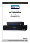
1
Built-in Duplex Multiplexer & Pan/Tilt Control
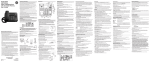
14” COLOR OBSERVATION SYSTEM
Built-in Duplex Multiplexer
Built-in Pan/Tilt Control
Real-Time Display
LIVE/PB Digital Zoom
Owner’s Manual
SAFETY INFORMATIONS
These symbols with supplemental markings are at the rear of the monitor
CAUTION
RISK OF ELECTRIC SHOCK
DO NOT OPEN
CAUTION :
TO REDUCE THE RISK OF ELECTRIC SHOCK, DO NOT REMOVE COVER,
NO USER-SERVICEABLE PARTS INSIDE. REFER SERVICING TO QUALIFIED
SERVICE PERSONNEL.
Explanation of Symbols
The lightning flash with arrowhead symbol, with an equilateral triangle, is intended
to alert the user to the presence of uninsulated "dangerous voltage" within the
product's enclosure that may be of sufficient magnitude to constitute a risk of
electric shock to persons.
The exclamation point within an equilateral triangle is intended to alert the user to
the presence of important operating and maintenance (servicing) instructions in the
literature accompanying the product.
WARNING : TO REDUCE THE RISK OF FIRE OR ELECTRIC SHOCK, DO NOT EXPOSE THIS UNIT TO
RAIN OR MOISTURE.
NOTE : This equipment has been tested and found to comply with the limits for a Class A digital device, pursuant to part 15 of
the FCC Rules. These limits are designed to provide reasonable protection against harmful interference when the equipment is
operated in a commercial environment. This equipment generates, uses, and can radiate radio frequency energy and, if not
installed and used in accordance with the instruction manual, may cause harmful interference to radio communications.
Operation of this equipment in a residential area is likely to cause harmful interference in which case the user will be required to
correct the interference at his own expense.
The user may find the following booklet prepared by the Federal Communications Commission helpful :
HOW TO IDENTIFY AND RESOLVE RADIO-TV INTERFERENCE PROBLEMS.
This booklet is available from the US Government Printing Office, Washington, DC 20402, Stock Number004-000-00345-4
CAUTION : CHANGES OR MODIFICATIONS NOT EXPRESSLY APPROVED BY THE PARTY RESPONSIBLE FOR COM
PLIANCE COULD VOID THE USER’S AUTHORITY TO OPERATE THE EQUIPMENT.
SAFETY INSTRUCTIONS
Warning! Important Safety Instructions
1) Read Instructions
All the safety and operating instructions should
be read before the appliance is operated.
2) Retain Instructions
The safety and operating instructions should be
retained for future reference.
3) Heed Warnings
All warnings on the product and in the
operating instructions should be adhered to.
mounting accessory recommended by the
manufacturer.
9) An product and cart combination should be
moved with care. Quick stops, excessive force,
and uneven surfaces may cause the product and
cart combination to overturn.
Portable cart warning
4) Follow Instructions
All operating and use instructions should be
followed.
5) Cleaning
Unplug this product from the wall outlet before
cleaning. Do not use liquid cleaners or aerosol
cleaners. Use a damp cloth for cleaning the unit.
Exception: A product that is meant for
uninterrupted service and that for some
specific reason, such as the possibility of the loss
of an authorization code for a CATV converter, is
not intended to be unplugged by the user for
cleaning or any other
purpose, may exclude the reference to
unplugging the product in the cleaning
description otherwise required in 5).
6) Attachments
Do not use attachments not recommended by the
product manufacturer as they may cause
hazards.
7) Water and Moisture
Do not use this product near water,
for example near a bath tub, wash bowl, kitchen
sink, or laundry tube in a wet
basement or near a swimming pool
and the like.
8) Accessories
Do not place this product on an unstable cart,
stand, tripod, bracket or table.
The product may fall, causing serious injury to a
child or adult, and serious damage to the
product. Use only with a cart, stand,
tripod, bracket or table recommended by the
manufacturer, or sold with the product. Any
mounting of the product should follow the
manufacturer's instructions, and should use a
10) Ventilation
Slots and openings in the cabinet are
provided for ventilation and to ensure
reliable operation of the product and to
protect it from overheating and these
openings must not be blocked or covered.
The openings should never be blocked by
placing the product on a bed, sofa, rug or other
similar surface. This product should not be
placed in a built-in installation such as a
bookcase or rack unless proper
ventilation is provided or the manufacturer's
instructions have been adhered to.
11) Power Sources
This product should be operated only from the
type of power resource indicated on the marking
label. If you are not sure of the type of power
supply to your home, consult your appliance
dealer or local power company. For products
intended to operate from
battery power or other sources, refer to the
operating instructions.
12) Grounding or Polarization
This product is equipped with a polarized
alternating-current line plug (a plug having one
blade wider than the other.) This plug will fit into
the power outlet only one way. This is a safety
feature. If you are unable to insert the plug fully
into the outlet, try
reversing the plug. If the plug should still fail to
fit, contact your electrician to replace your
obsolete outlet. Do not defeat the safety purpose
of this polarized plug.
SAFETY INSTRUCTIONS
Alternate Warnings
This product is equipped with a three-wire
grounding-type plug a plug having a third
(grounding) pin. This plug will only fit into a
grounding-type power outlet. This is a safety
feature. If you are unable to insert the plug into
the outlet, contact your electrician to replace your
obsolete outlet. Do not defeat the safety purpose
of the grounding-type plug.
17) Power Lines
An outside antenna should not be located in the
vicinity of overhead power lines or other electric
light or power circuits, or where it can fall into
such power lines or circuits. When installing an
outside antenna system, extreme care should be
taken to keep from touching such power lines or
circuits as
contact with them may be fatal.
13) Power-Cord Protection
Power-supply cords should be routed so that
they are not likely to be walked on or pinched by
items placed upon or against them paying
particular attention to cords at plugs,
convenience receptacles, and the point where
they exit from the product.
18) Overloading
Do not overload wall outlets, extension cords, or
integral convenience receptacles as this can
result in a risk of fire or electric shock.
14) Protective Attachment Plug
The product is equipped with an attachment plug
having overload protection. This is a safety
feature. See instruction Manual for replacement
or resetting of protective device. If replacement of
the plug is required, be sure the service
technician has used a replacement plug specified
by the manufacturer that has the same overload
protection as the original plug.
15) Outdoor Antenna Grounding
If an outside antenna or cable system is
connected to the product, be sure the
antenna or cable system is grounded so as to
provide some protection against voltage surges
and built-up static charges. Article 810 of the
National Electrical Code. ANSI/NFPA 70,
provides information with regard to proper
grounding of the mast and supporting structure,
grounding of the
lead-in wire to an antenna discharge unit, size of
grounding conductors, location of antennadischarge unit, connection to grounding
electrodes, and requirements for the grounding
electrodes. See Figure 1-1.
16) Lightning
For added protection for this product during a
lightning storm, or when it is left
unattended and unused for long periods of time,
unplug the product from the wall outlet and
disconnect the antenna or cable
system. This will prevent damage to the product
due to lightning and power line surges.
19) Object and Liquid Entry
Never push objects of any kind into this
product through openings as they may touch
dangerous voltage points or short out parts that
could result in a fire or electric shock. Never spill
liquid of any kind on the receiver.
20) Servicing
Do not attempt to service this product
yourself as opening or removing covers may
expose you to dangerous volt-age or other
hazzards. Refer all servicing to qualified service
personnel.
21) Damage Requiring Service
Unplug the product from the wall outlet and refer
service opening to qualified service
personnel under the following conditions:
a)when the power-supply cord or plug is
damaged,
b)if liquid has been spilled, or objects have fallen
into the product,
c) if the product has been exposed to rain or
water.
d)if the product does not operate normally by
following the operating instructions. Adjust only
the controls that are covered by the operating
instructions as an improper adjustment of other
controls may result in dam-age and will often
require extensive work by a qualified technician
to restore the video product to its nor-mal
operation.
e)If the product has been dropped or
damaged in any way, and
f)When the product exhibits a distinct change in
performance - this indicates a need for service.
SAFETY INSTRUCTIONS
22) Replacement Parts
When replacements parts are required, be sure
the service technician has used replacements
parts specified by the
manufacturer or have the same
characteristics as the original part. Unauthorized
substitutions may results in fire, electric shock or
other hazards.
23) Safety Check
Upon completion of any service or repairs to this
receiver, ask the service technician to perform
safety checks to determine that the product is in
proper operating condition.
24) Wall or Ceiling Mounting
The product should be mounted to a wall or
ceiling only as recommended by the
manufacturer.
25) Heat
The product should be situated away from heat
sources such as radiators, heat
registers, stoves, or other products
(including amplifiers) that produce heat.
Figure 1-1
Antenna grounding as per
National Electrical Code, ANSI/NFPA70
EXAMPLE OF
ANTENNA GROUNDING
ANTENNA
LEAD IN WIRE
GROUND CLAMP
ELECTRIC
SERVICE
EQUIPMENT
ANTENNA
DISCHARGE UNIT
(NEC SECTION 810-20)
GROUNDING
CONDUCTORS
(NEC SECTION 810-21)
GROUND CLAMPS
NEC NATIONAL ELECTRICAL CODE
S2898A
POWER SERVICE GROUNDING
ELECTRODE SYSTEM
(NEC ART 250, PART H)
CONTENTS
INTRODUCTION ................................................................................................................................... 1
MONITOR SYSTEM PART NAME
FRONT PANEL ............................................................................................................................... 2
BACK PANEL .................................................................................................................................. 3
MULTIPLEXER SYSTEM OPERATION
STARTING THE SETUP MODE ..................................................................................................... 4
MAIN MENU ................................................................................................................................... 4
SUB MENU SETTING .................................................................................................................... 5
CAMERA INPUT ............................................................................................................................. 5
CHANNEL TITlE ............................................................................................................................. 5
DATE / TIME ................................................................................................................................... 6
AUTO SWITCH ............................................................................................................................... 6
REC TYPE ...................................................................................................................................... 7
ALARM/LOSS ................................................................................................................................. 7
ALARM/LOSS LIST ......................................................................................................................... 8
OBSERVATION CAMERA OPERATION
CAMERA PART ............................................................................................................................... 9
CAMERA INSTALLATION ............................................................................................................... 9
PAN/TILT DOME CAMERA OPERATION
CAMERA PART ............................................................................................................................. 10
CAMERA INSTALLATION ............................................................................................................. 10
REMOTE CONTROL UNIT ........................................................................................................... 11~12
SYSTEM OPERATION
STANDARD CAMERA OPERATION ............................................................................................ 13
MULTIPLE STANDARD CAMERA OPERATION .......................................................................... 13
OBSERVATION CAMERA TWO WAY INTERCOM INSTALLATION ............................................ 14
OBSERVATION CAMERA ALARM DEVICE INSTALLATION ...................................................... 14
PAN/TILT DOME CAMERA OPERATION ..................................................................................... 15
MULTIPLE PAN/TILT DOME CAMERA OPERATION .................................................................. 15
MULTIPLE SYSTEM OPERATION ............................................................................................... 16
BNC CAMERA SYSTEM OPERATION ........................................................................................ 16
AUXILIARY OPERATION
INSTALLATION ............................................................................................................................. 17
VCR OPERATION .................................................................................................................. 17~18
ALARM OPERATION .............................................................................................................. 19~21
VIDEO LOSS ................................................................................................................................ 21
SPECIFICATION
14” BUILT-IN MUX COLOR MONITOR ........................................................................................ 22
MULTIPLEXER ............................................................................................................................. 23
CAMERA (PAN/TILT DOME COLOR CAMERA) .......................................................................... 24
CAMERA (OBSERVATION COLOR CAMERA) ............................................................................ 25
ACCESSORIES .................................................................................................................................. 26
USER’S GUIDE ............................................................................................................................. 27~28
TROUBLE SHOOTING GUIDE .......................................................................................................... 29
V
PRIOR TO USE
PRIOR TO USE
This is the basic manual for Built-in Mux Control 14” Color Observation System user. The content
of this manual is focused on product introduction, installing method, connecting method with other
devices, using method of various functional buttons, and system setting method with the setup
menu.
Before using this equipment, this manual should be read not only by first users, but also by the
users who are already familiar with this system or any other similar device in accordance with the
precautions stated within the manual.
Before getting started with this equipment, it should be emphasized that the user must
consult and receive help from the dealer where the product was purchased when opening the case
and fixing the internal parts of the system for upgrade or repair.
And also if you have any further questions related to using this equipment or think you have a
problem with the product, please consult your dealer.
UNPACKING
Upon purchase of this system, unpack the box and put the unit on a floor stand, or place the unit
where you are going to install the system. Please check the contents of the package as listed below.
IN CASE of Observation system
• Monitor main unit
• Observation Camera (or Pan/Tilt Dome Camera)
• 20m(60ft) Multi(Din or RJ-11) Cable
• Instruction Manual
• Power Cable
• Remote Controller (Optional)
IN CASE of Only Monitor
• Monitor main unit
• Instruction Manual
• Power Cable
VI
INTRODUCTION
This equipment will give you added security and comfort for many years. It is easy to install in almost anywhere you
need audio/video surveillance. To safely use all the high technical functions of the unit, please read the installation
and operating instruction in manual, and keep it for the future reference. Also, it can directly control Pan/Tilt Dome
Camera without any extra controller.
FUNCTIONS
• Built-in Real Time 4 channel Color Duplex Multiplexer
• Built-in Auto Switcher
• Built-In Digital Multi Comb Filter (NTSC/PAL)
• Built-In Pan/Tilt Dome Camera Control (Multi <Din, RJ> Jack)
• Built-In Camera Vertical GEN-Lock (Multi <Din, RJ> Jack)
• Multi System (NTSC/PAL)
• Alarm In/Out & Two Way Talk
• Horizontal Resolution 420TV Lines
• Free Voltage (AC 100V ~ 240V, 50/60Hz)
• On Screen Menu Control & Digital Picture Menu Control
1
MONITOR SYSTEM PART NAME
Front Panel
15
1
2
4
6
8
3
5
7
9
10
1 CHANNEL SELECT BUTTONS
- In Live / PB mode : When desired channel button is
pressed, a full screen of the channel is displayed.
- Menu(S.MENU) mode
Button : To move throughout each item of the Main
Menu or that of the sub menu to set it up.
Button : To increase or decrease the value of each
item.
- Pan/Tilt Dome Camera Control
2 QUAD
Quad Screen display in LIVE or PB.
3 AUTO
Sequentially switching the channel in only LIVE MODE
4 LIVE/PB
Switching the LIVE Mode or Play Back Mode.
5 PB THRU
Monitoring the recorded multiplexer OUT signal or
Playback signal of TIME LAPSE VCR.
6 ZOOM
Zooming the special part of the screen in 2 Times,
pressing the button again, the screen will be larger 2
Times, and then move the highlighted area by using the
arrow buttons (,,,).
7 FREEZE
When a Full screen in selected and user presses the
“FREEZE” button, the screen will be frozen, and the
alphabet “F” will be displayed on to the selected channel.
If user presses the button once more, the Freeze will be
deactivated. When a Quad screen is selected, if a user
presses the “FREEZE” button and desired channel button,
then the selected channel screen will be frozen.
8 IR RECEIVER
Receiving the remocon signal.
9 MIC
MIC input when pressed only TAlK button in the channel
selected.
11
12
13
14
10 S.MENU(SYSTEM MENU)
If user presses this button, it will display the setup menu.
User can change the various functional settings of this
system from the setup menu. Use the arrow buttons( ) to move from menu to menu, or change the value of
the sub menu.
11 ENTER / PAN/TILT
• Menu(system set-up) mode : When the modification of
each Sub Menu item is complete, press this button to
save the settings. Use this button to enter a Sub Menu of
the Main Menu or to return to the Main Menu from Sub
Menu by pressing this button on “EXIT”
• Pan/Tilt On/Off button. Assuming that Pan/Tilt dome
camera is connected to any channel, if user selects the
channel and presses this button, the Pan/Tilt control mode
will be started. And using the arrow buttons ( ), user
can freely control the Pan/Tilt dome camera to its taste.
(If a user uses more than two Pan/Tilt dome camera, each
pressing the Pan/Tilt button will select from CH1 to CH4,
to control the each camera.)
12 TALK
Press and hold this button to talk through to the camera
and release it to receive.
13 ACTION
This button can lock or release the door open, or activate
other alarm device. It will be used to remotely open a
door, or activate different kinds of detectors.
(Send only trigger signal)
14 P. MENU (PICTURE MENU)
• Each pressing this button in VCR and Live mode, the
Sub Menu will sequentially displayed on to the screen.
Use volume buttons( ) to adjust each Sub menu and
press P. Menu button to deactivate.
• Contrast : Use to adjust the contrast of the screen.
• Brightness : Use to adjust the brightness of the screen.
• Color : Use to adjust the density of color.
• Tint : Use to adjust the tint of color.(NTSC only)
• Sharpness : Use to adjust the sharpness of color.
15 SPEAKER
2
MONITOR SYSTEM PART NAME
Back Panel
1 AC INPUT
This is an input terminal that connects to AC 100~240V
power.
2 VIDEO INPUT/OUTPUT CONNECTORS
• BNC camera inputs 1~4 : These inputs are used for
standard cameras with BNC type connectors.
• Looping outputs 1~4 : These are looping outputs for
cameras on through. It can be used to display or record
the pictures on a separate monitor or recorder.
6
ALARM TERMINAL
7
CAMERA INPUT MULTI(DIN) JACKS
To connect to 4 cameras, such as our Pan/Tilt Dome
Camera and general Observation Camera.
A) +12V
B) Audio in
A
D
C) CAPW
(Camera auto amp)
E
B
D) Video in
E) Audio out (Alarmin)
C
F
F) V-sync (Gen-lock)
3 VCR VIDEO/AUDIO INPUT/OUTPUT CONNECTORS
Video/Audio input connectors are for receiving video/audio
signal from VCR or another video unit.
Video/Audio output connectors are for transmitting
video/audio signal from a camera to another monitor.
Also used in recording on VCR.
4 MONITOR VIDEO/AUDIO OUTPUT CONNECTORS
Video/Audio output for slave monitor. Connect via double
male to double male RCA
leads of required length.
NB : Maximum recommended distance between master
and slave monitor is 20m.
CAMERA INPUT RJ JACKS
5 ACTION TERMINAL
To activate several kinds of detectors, such as Door Lock
and Alarm Device.
F
E
C
8
3
A
B
D
MAIN POWER SWITCH
A) Alarm + Gen Lock
B) B+ (DC 15V)
C) Audio out + Pan/Tilt
D) Video in
E) Audio in
F) GND
MULTIPLEXER SYSTEM OPERATION
This chapter shows you how to execute various modes using the system setup menu.
STARTING THE SETUP MODE
1. Check the power cables of the equipment connected to
Monitor and turn the power switch.
2. Press the S. Menu button on the front panel.
Note
Only while in Live Mode, you can enter the setup mode.
MAIN MENU
Press the “S. MENU” button on the front of the system, the main menu of the system setup appears as follows.
• Modifying settings
Select a menu item by using the buttons and press ENTER and then you find the SUB Menu and you can
change the setup by press the direction Key (,,, )
• Saving the Setting / Returning to the Main Menu
When the modification of each sub menu item is complete, press the Enter button to save the settings. Use this
button to enter a Sub Menu of the Main Menu or to return to the Main Menu from Sub Menu, placed the cursor
on “EXIT”.
4
MULTIPLEXER SYSTEM OPERATION
SUB MENU SETTING
1. CAMERA INPUT SET
- Set channel [ON], if camera is connected to the channel, and set channel
[OFF] if camera is not connected to the channel.
- If the channel is set to [OFF], missing video input signals are not treated
as LOSS.
• From the <MENU>, set the cursor on the 1. CAMERA INPUT SET item
using and keys, and press ENTER key.
[CAMERA INPUT SET] screen will be displayed.
• In the screen, set the cursor on the channel to configure using and
keys, select using or key, and set the channel status ON or
OFF using and keys.
Pressing the S MENU key takes the user to the previous menu
(<MENU>).
2. CHANNEL TITLE
- Enter the title of each channel.
• In <MENU>, set the cursor on the 2.CH_TITLE SET item using and
keys, then press ENTER key. [CH_TITLE] screen appears.
• Use and keys to select, use and keys to move and select
desired alphabet, and select the alphabet from the character table using
and keys.
5
MULTIPLEXER SYSTEM OPERATION
3. DATE/TIME SET
- Setting up date and time
- 1. DATE FORM: (1) : Select one of the following appropriate date forms
to display date.
<1>DD/MM/YYYY : Day / Month / Year
<2>MM/DD/YYYY : Month / Day / Year
<3>YYYY/MM/DD : Year / Month / Day
• Set the cursor on the 3.DATE/TIME SET using , and keys from the
<MAIN MENU>, and then press ENTER key. [DATE/TIME SET]
screen appears.
• Press or key to move the cursor up and down.
• To setup date form, select one among <1>, <2> and <3> date forms
using or keys and change the date form using and keys
depending on the date display convention of each country.
• To setup date, set the cursor on the date using and keys,
then move to the field to change using and keys, and set the
value using and keys.
• To set up time, set the cursor on the time using and keys, then
move to the field to change using and keys, and set the value
using and keys.
• To escape from current setting mode, press S MENU key.
• If a user want to record the Time & Date on the picture, a user should
have "Display On" of its Time lapse VCR turned on, because this system
does not support Time & Date on display in recording mode.
4. AUTO SWITCH SET
- Set the CHANNEL DWELL TIME for AUTO SWITCH operation.
• You can set the time within the range of 0 to 30 second.
From the <MENU>, set the cursor on the 4.AUTO SWITCH SET using
and keys, and press ENTER key. [AUTO SWITCH] screen
appears.
• Set the cursor on the appropriate channel using and keys, select
using and keys, and set using and keys.
• When DWELL TIME setting is completed, press the S MENU key to
return to the MAIN MENU screen.
6
MULTIPLEXER SYSTEM OPERATION
5. REC TYPE SET
- Allows setting of the recording mode of TIME LAPSE VCR to be
connected with MULTIPLEXER.
• Set the cursor on the 5.REC TYPE SET using and keys,
and press ENTER key to enter the SUB MENU on the right.
• To record intermittently, locate the cursor on the 1. TIMELAPSE using
and keys, and press ENTER key.
To record in 60 fields/sec (NTSC standard) or 50 fields/sec
(PAL standard), select 2. REAL TIME and press ENTER key.
• In case of TIME LAPSE record mode, connect SW TRIGGER signal
from VCR to the TERMINAL SW IN of main unit, connect GND signal to
COM, and connect SW-OUT signal to VTI.
If the connection is not properly established, only the signal from a
certain camera is not recorded.
If the VCR’s record time setting is something other than the TIME
LAPSE mode, signals from 4 cameras may not be recorded properly.
IN
COM
OUT
S/W OUT
TYPICAL TIME LAPSE RECORDER REAR VIEW
• In case of REAL TIME record mode, camera signal output is
automatically switched by fields regardless of the SW TRIGGER signal
from the VCR.
• In case of TIME LAPSE record mode, camera signal output is
automatially switched by field or frame of the SW TRIGGER signal from
the TIME LAPSE VCR.
• Switch out timing of TIME LAPSE VCR must be selected frame.
If switch out timing of TIME LAPSE VCR is selected field, the recording
image missed some fields.
• Press the S MENU key to return to the MAIN MENU.
6. ALARM/LOSS SET
- ALARM / LOSS BUZZER SET-UP
1. ALARM : Set BUZZER ON/OFF when ALARM occurs.
2. LOSS : Set BUZZER ON/OFF when LOSS occurs.
3. HOLD TIME: Time to continue ALARM state after ALARM occurs.
• From the <MENU>, set the cursor on the 6. ALARM/LOSS SET using
and keys, and press ENTER. [ALARM/LOSS SET] screen
appears. Set the cursor on the setting entry using and keys and
set or change the values in the entry using and keys.
• In [ALARM/LOSS SET] screen, configure 3. HOLD TIME to 5 seconds
interval for the first second to the first minute, and 1 minute interval for
the first minute to the 30th minute, as described above.
7
MULTIPLEXER SYSTEM OPERATION
7. ALARM / LOSS LIST
• To view up to 10ALARM/LOSS history records,
From the <MENU>, set the cursor on the 7. ALARM/LOSS LIST using the and keys, and press ENTER.
[ALARM / LOSS LIST] screen appears as illustrated below. If the number of occurred ALARM/LOSS
exceeds the limit (10), the latest item replaces the oldest items.
No.1 LOSS occurred in camera No.3 at August 24th 2001 3:23:10 a.m.
No.2 ALARM occurred in sensor No.1 at August 24th 2001 8:25:40 a.m.
No.10 ALARM occurred in sensor No.2 at August 24th 2001 9:00:00 am.
• Press the (DELETE) TALK key to delete all history records. Please confirm the records to delete
before delete them.
• Press ENTER key to return to the [ALARM/LOSS SET] screen.
• To return to MAIN MENU, press the S.MENU button.
8
OBSERVATION CAMERA OPERATION
CAMERA PART
RJ TYPE
DIN TYPE
IRIS
4
INTERPHONE
5
3
2
8
6
TERMINAL
7
TO MONITOR
LEVEL
9
MONITOR
1
10
1. CCD CAMERA LENS
Deliver sharp image to the CCD sensor.
5. MONITOR INPUT JACK
Din connect the cable with the monitor.
2. MICROPHONE
Pick up sound around the camera.
6. INTERPHONE
3. SPEAKER
Delivers the sound from the monitor
4. ALARM TERMINAL
Connect an optional alarm device to this
terminal.
IN
GND
B+
TERMINAL
IN Alarm input (normally open)
GND Ground
B+ Power output +12V DC 100mA
7. MONITOR INPUT JACK
RJ-11 Connector cable to the monitor.
8. DC IRIS LENS CONNECTOR
When using on DC iris lens.
9. LEVEL
Auto DC iris type video level control.
10. BRACKET
Permanent installation using pedestal stand.
1. Attach the Pedestal using 4 screws.
2. Attach the Camera onto the Pedestal
and tighten the screw.
CAUTION : Keep camera installed away from direct sunlight. Also avoid places where humidity is high or
where the camera is not protected from rain. The mounting bracketmust be attached to a
structural object such as a wall stud or ceiling rafter using suitable fastener. Do not touch the
glass of the lens. This could damage the delicate coating on its surface. If the lens has to be
cleaned, use a special lens cleaning tissue available at any good camera store.
9
PAN/TILT DOME CAMERA OPERATION
CAMERA PART
Electrical power is not connected to the dome and observation / quad monitor during installation.
A
105
TOP VIEW
107
FRONT VIEW
105
or
CAMERA IN STALLATION
Adaptor plate
Ø3 x 20 screw
Hook
Base (hold base when you
twist to attach the
dome to adaptor plate)
Swivel
Bubble
Be sure that no power is connected to dome camera and observation / quad monitor during installation.
1. Twist open the clear dome cover to CCW to reach inside the dome camera.
2. Place the controller on the desk or proper appropriate location.
3. Connect the controller and the observation / quad monitor with 10ft din cable.
(Included in the package of controller)
4. Wiring the 60ft din cable from controller to dome camera.
5. Attach the adaptor plate on the ceiling. Using Ø3 X 20 screws (included)
6. Twist the base of the dome camera to the adaptor plate on the ceiling.
Do not hold clear bubble or swivel, when you attach the dome to adaptor plate.
7. Attach one end of DIN connector to the back of the control unit’s connector. (named camera)
Repeat sequence 1 through 7 until install all dome cameras.
10
REMOTE CONTROL UNIT
POWER
ID NO
0
1
2
3
4
5
6
7
8
9
1
CH1
2
CH3
3
CH2
4
VCR
RECORD
LIVE/PB
PLAY
RB THRU
FREEZE
QUAD/MULTI
6
CH1
CH3
MENU
CH4
ENTER/P.T
VOL
RECORD
LIVE/PB
P.MENU
PLAY
PB THRU
VOL
10
FREEZE
ZOOM
11
QUAD/MULTI
8
5
CH4
14
VOLUME UP
ENTER/P.T
P.MENU
15
16
17
9
12
MENU (SYSTEM)
CH2
VCR
7
13
ACTION
AUTO
MULTIPLEXER
CNTROL
18
19
20
VOLUME DOWN
ACTION
ZOOM
AUTO
This remote control unit is commonly used in various model.
Some keys are not available in the special model.
CAUTION
Danger of explosion if battery is incorrectly replaced.
Replace only with the same or equivalent type
recommended by the manufacturer.
Dispose of used batteries according
to the manufacture’s instructions.
11
REMOTE CONTROL UNIT
1 POWER
Press to turn the MONITOR on and off.
12 QUAD/MULTI
Used in the quad display monitor only
2 CH1 ( )
CH1 button enables the camera 1 to be displayed in a
single mode.
13 MENU(SYSTEM)
Display the system main menu on the screen.
You can set up CAM INPUT SET, CH_TITLE SET,
DATE/TIME SET, AUTO SWITCH SET, REC TYPE SET
ALARM/LOSS SET and ALARM/LOSS LIST.
3 CH2 ( )
CH2 button enables the camera 2 to be displayed in a
single mode.
4 CH3 ( )
CH3 button enables the camera 3 to be displayed in a
single mode. Also used to highlight selections on the
system main menus.
5 CH4 ( )
CH4 button enables the camera 4 to be displayed in a
single mode.
Also used to highlight selections on the system main
menus.
6 VCR
Press this button to display the picture of VCR playback.
7 RECORD
Used in the built-in Quad monitor only.
14 VOLUME UP
Press to increase the volume level. Also used to
select items on the on-screen picture menu.
15 ENTER/P.T
If this key is pressed, the system goes to the PAN/TILT
control mode, and then you can change the camera view
position by pressing the up/down, right/left button.
16 P.MENU (PICTURE MENU)
Display the Picture Menu on the screen.
You can set up CONTRAST, BRIGHTNESS, COLOR,
TINT(NTSC only) and SHARPNESS.
17 VOLUME DOWN
Press to decrease the volume level. Also used to
select items on the on-screen picture menu.
18 ACTION
It switches the internal relay to put on.
8 LIVE/PB
Used in the Mux monitor only
9 PLAY
Press this button to display the picture of VCR playback.
19 ZOOM
Zoom in on the picture in LIVE MODE &PLAY BACK
MODE.
20 AUTO
This button makes the quad processor switched the signal
sources to be displayed sequentially.
10 RB THRU
Used in the Mux monitor only
11 FREEZE
Press this button to stop the image temporarily.
INSERTING THE BATTERIES IN THE REMOTE CONTROLLER
You must insert or replace the batteries in the remote controller when you:
Purchase the set. (AAA size 1.5V 2)
Find that the remote controller is no longer operating correctly.
1
Remove the cover of the remote
controller by pressing the symbol and
pulling the cover space in the
direction of the arrow.
2
Insert 2 batteries(AAA size),
taking care to respect the polarities.
3
Replace the cover by pushing it in the
direction of the arrow.
! You can use your remote controller within a distance of 7~10m and an angle of 30 degrees from the left and right sides of the remote controller receptor of your monitor.
12
SYSTEM OPERATION
STANDARD CAMERA OPERATION
MONITOR REAR VIEW
STANDARD CAMERA
CH1
CH2
CH3
or
CH4
CH1
CH2
CH3
CH4
VIDEO
AUDIO
MONITOR
OUT
Some models has the RJ IN. (Optionable)
STANDARD CAMERA INSTALLATION
MULTIPLE CAMERA OPERATION
MONITOR REAR VIEW
CAMERA REAR VIEW
TERMINAL
DIN
TO MONITOR
CH1
CH2
CH3
CH4
or
ACTION
IRIS
CH1
INTERPHONE
H3
CH4
VIDEO
AUDIO
VCR
VIDEO
CH2
AUDIO
CH3
MONITOR
OUT
LEVEL
MONITOR
CH4
Some models has the RJ IN. (Optionable)
MULTIPLE CAMERA INSTALLATION
1. Connect all camera cables and verify operation, as shown above.
(You should plug out while you connect additional cameras).
Each channel is exclusive with same NO of BNC Input.
2. When you push the auto button, monitor goes to auto switching mode.
13
SYSTEM OPERATION
OBSERVATION CAMERA TWO WAY INTERCOM INSTALLATION
Camera with intercom installation
(RJ TYPE)
(DIN TYPE)
CAMERA
(REAR VIEW)
CAMERA
(REAR VIEW)
IRIS
TERMINAL
INTERPHONE
TO MONITOR
LEVEL
2m RJ Cable
(Supplied)
MONITOR
(REAR VIEW)
2m DIN Cable
(Supplied)
MONITOR
MONITOR
(REAR VIEW)
INTERCOM BOX
CH1
CALL
INTERCOM BOX
1
CH2
CH1
CH3
CALL
CH2
CH4
CH3
CH4
ACTION
IN
VIDEO
POWER
AUDIO
OUT
AC IN
CH1
CH2
CH3
CH4
VIDEO
VIDEO
MONITOR
OUT
AUDIO
VCR
Normal Standard DIN Cable
(20m, Supplied)
ACTION
IN
VIDEO
OUT
AUDIO
Normal Standard RJ Cable
(20m, Supplied)
POWER
AC IN
CH1
CH2
CH3
CH4
VIDEO
AUDIO
VIDEO
VCR
MONITOR
OUT
DOORBELL : There is a push button on the intercom box, which can be used as a doorbell when the
button is pushed, a buzzer will sound at the monitor after which the pictures is switched to the
corresponding camera.
NOTE : Do not use telephone cable or other special cable. If the provided camera cable is not long enough
or Additional and longer cables can be purchased from your distributor.
OBSERVATION CAMERA ALARM DEVICE INSTALLATION
Camera with alarm device installation
(RJ TYPE)
(DIN TYPE)
MONITOR
(REAR VIEW)
MONITOR
(REAR VIEW)
CAMERA
(REAR VIEW)
CAMERA
(REAR VIEW)
IRIS
TERMINAL
INTERPHONE
CH1
CH1
CH2
CH2
TO MONITOR
CH3
LEVEL
MONITOR
CH3
CH4
CH4
ACTION
ACTION
IN
IN
VIDEO
VIDEO
POWER
POWER
AC IN
AC IN
AUDIO
OUT
CH1
CH2
CH3
VIDEO
CH4
VIDEO
AUDIO
VCR
AUDIO
OUT
CH1
MONITOR
OUT
CH2
CH3
CH4
VIDEO
External Alarm Device Cable
To any N.O alarm device
VIDEO
AUDIO
VCR
MONITOR
OUT
OR
OR
External Alarm Device Cable
To any N.O alarm device
OR
OR
External Alarm Device Cable
External Alarm Device Cable
OR
OR
Passive Infrared Detector
Passive Infrared Detector
OR
OR
Passive Infrared Detector W/Power Supply
Passive Infrared Detector W/Power Supply
14
SYSTEM OPERATION
PAN/TILT DOME CAMERA OPERATION
MONITOR REAR VIEW
CH1
STANDARD DOME CAMERA
CH2
CH3
CH1
or
CH4
CH2
CH3
CH4
VIDEO
AUDIO
EO
MONITOR
OUT
AUDIO
VCR
PAN/TILT DOME CAMERA INSTALLATION
MULTIPLE PAN/TILT DOME CAMERA OPERATION
MONITOR REAR VIEW
CH1
CH2
CH3
CH4
or
ACTION
CH1
H2
CH3
VIDEO
CH4
VIDEO
AUDIO
VCR
VIDEO
CH2
AUDIO
CH3
MONITOR
OUT
CH4
MULTIPLE PAN/TILT CAMERA INSTALLATION
1. Connect all camera cables and verify operation, as shown above.
(You should plug out while you connect additional cameras).
Each channel is exclusive with same NO of BNC Input.
2. When you push the auto button, monitor goes to auto switching mode.
15
SYSTEM OPERATION
MULTIPLE SYSTEM OPERATION
ID NO
0
1
2
3
4
5
6
7
8
9
Built-in Mux
Monitor
CH1
CH3
MENU
VCR
ENTER/P.T
CH4
Slave monitor
CH2
RECORD
LIVE/PB
PLAY
PB THRU
FREEZE
ZOOM
QUAD/MULTI
VOL
P.MENU
VOL
ACTION
AUTO
MULTIPLEXER
CNTROL
CH1
CH2
VCR RECORD PLAY
CH3
CH4
AUTO
S.MENU ENTER
TALK ACTION P.MENU
VOLUME
POWER
MONITOR
VIDEO
A
MIC
PAN/TILT
ADJUST
VCR FREEZE
ON / OFF
SHARP BRIGHT TINT
COLOR CONTRAST
VOLUME
POWER
B
ADJUST
(ID Remote controller)
(Typical Time Lapse VCR)
BNC CAMERA SYSTEM OPERATION
IN
VIDEO
OUT
AUDIO
POWER
AC IN
CH1
CH2
CH3
CH4
VIDEO
VIDEO
AUDIO
VCR
MONITOR
OUT
DSS
ON ON ELC
IRIS
VIDEO
DC
FL DSS ALC
OFF
DC LEVEL
VIDEO
12VDC GND
16
AUXILIARY OPERATION
INSTALLATION
MONITOR REAR VIEW
CH1
CH2
EXTRA MONITOR
CH3
CH4
ACTION
VIDEO
AUDIO
CH1
CH2
CH3
VIDEO
CH4
VIDEO
AUDIO
VCR
MONITOR
OUT
EXTRA MONITOR INSTALLATION
VCR OPERATION
CH1
CH2
CH3
CH4
ACTION
IN
VIDEO
OUT
AUDIO
POWER
AC IN
CH1
CH2
CH3
VIDEO
CH4
VIDEO
MONITOR
OUT
AUDIO
VCR
IN
COM
OUT
S/W OUT
TYPICAL TIME LAPSE RECORDER REAR VIEW
OBSERVATION MONITOR WITH A RECORDER
1. In case of TIMELAPSE record mode, connect SW TRIGGER output signal from VCR to the
TERMINAL SW IN of main unit, connect GND signal to COM, and connect SW-OUT signal to VTI.
If the connection is not properly established, only the signal from a certain camera may be recorded.
If the VCR’s record time setting is something other than the TIMELAPSE mode, signals from 4
cameras may not be recorded properly.
17
AUXILIARY OPERATION
2. In case of REAL TIME record mode, camera signal output is automatically switched by fields regardless of the
SW TRIGGER signal from the VCR.
In case of TIME LAPSE record mode, camera signal output is automatially switched by field or frame of the
SW TRIGGER signal from the TIME LAPSE VCR.
Switch out timing of TIME LAPSE VCR must be selected frame.
If switch out timing of TIME LAPSE VCR is selected field, the recording image missed some fields.
3. Then, press the "REC" button on the VCR.
4. To play back, press the "PLAY" button on the VCR and press the PB KEY on the monitor at the
same time.
5. Verify that the monitor is displaying a good picture from the camera and make a test recording to
verify operation of the VCR.
6. Your system is now ready to do observation recording.
* When you are operating the normal VCR, make sure the VCR is in Line or AV Mode.
18
AUXILIARY OPERATION
ALARM OPERATION
A. Monitor Alarm Circuit
MONITOR ALARM CIRCUIT
B. Alarm Connection There are two ways to connect with alarm. One is to connect with terminal
Block on the back panel of monitor and the other is with AUX port on rear panel of camera.
B-a. Terminal Block Connection
or
ALARM SYSTEM
SENSOR 1
SENSOR 2
SENSOR 3
SENSOR 4
ALARM DEVICE INSTALLATION (In case of using TIME LAPSE VCR)
1. SW IN
-GND
: This is the COMMON Ground for ALARM OUT & IN.
-VTI
: This is the Trigger Input from the Time Lapse VCR for changing the channel
for multiplexing recording.
2. ALARM OUT
-HOT/COLD
: This is the ALARM OUT for the Time Lapse VCR or ALARM system.
(This terminal is normally open)
If the alarm is occured, this terminal is switched to closed. ("ACTIVE MAKE")
3. ALARM IN
-CH1~CH4
: These terminals are assigned to each camera alarm sensor or the special
alarm system.
The alarm sensor must be normally open type.
19
AUXILIARY OPERATION
C. ALARM OPERATION
When an alarm is activated, the associated camera video displays full screen, the word ALARM
displays on screen, a buzzer, if programmed "30 SEC", generates a continuous audible alarm for 30 seconds and
the alarm output relay activates.
If the second or third sensor is activated while the first alarm is operating, the screen will switch to the second or
third sensing camera. Pressing the VCR KEY resets the alarm condition.
*When connected to a time lapse VCR, the VCR will automatically switch to the normal mode when an alarm is
sensed. If the VCR was programmed (ex:24hrs, 72hrs then the VCR will automatically switch back once the alarm
is released.
(1) ALARM INPUT specification (Normally in “H” state due to FULL UP resistance of the MULTIPLEXER itself.)
(2) ALARM OUT specification.
The points of contact of RELAY are used as output (HOT/COLD, no polarity), and the points of contact are
open (NORMAL OPEN) during normally. However, the points of contact are closed (MAKE) during HOLD TIME
resulted from ALARM occurred.
The specification of points of contact is 5A 250VAC (Avoid connecting with the product that has higher capacity
than the specification).
(3) When a single ALARM occurs
If BUZZER is set “ON” from the ALARM/LOSS MENU, then BUZZER sounds.
To cancel ALARM, press any one of CH1~4, QUAD, AUTO, LIVE/PB, ZOOM, PB THRU, and FREEZE keys.
ALARM is canceled even if ALARM HOLD TIME is in progress.
The date, time and channel ALARM occurred are stored in the ALARM/LOSS LIST.
BUZZER sounds during ALARM HOLD TIME specified in ALARM MENU. ALARM and BUZZER sound
continues until the time set in HOLD TIME is reached.
If ALARM occurs while you are viewing in single screen or automatic serial switching is in progress, single
screen switches to QUAD screen. Even if ALARM is cancelled by pressing key or the expiration of HOLD TIME,
QUAD screen does not return to the original status.
(4) When multiple ALARMs occur.
If ALARM occurs while you are viewing in single screen or automatic serial switching is in progress, single
screen switches to QUAD screen. Even if ALARM is cancelled by pressing key or the expiration of HOLD TIME,
QUAD screen does not return to the original status.
“A”(For ALARM) mark is displayed on the channel where the ALARM occurred during HOLD TIME.
Other channels where ALARM occurred are also indicated by “A” mark and a new HOLD TIME begins since
the last ALARM occurred.
If ALARM occurs during setting the MENU, the MENU setting status is cancelled, and it performs Alarm
operation first. When HOLD TIME is expired, the channel where ALARM occurred is displayed.
(5) RECORD OUT when ALARM occurs.
If ALARM occurs in channel 1 or 3, “A” mark blinks at the bottom of the channel screen in QUAD screen.
The frequency of the alarmed channel is increased in record out so that the channel is more frequently recoded
20
AUXILIARY OPERATION
(near real-time recording).
e.g., If ALARM occurred in ALARM SENSOR 1 interoperating with camera 1, the order of record out would be :
1 - 2 - 1 - 3 - 1 - 4 - 1 - 1 - 2 - 1 - 3 - 1 - 4 - 1 - 1 - 2......
When ALARM is cancelled by pressing key or the expiration of HOLD TIME, the frequency of channel recording
is returned to the original status.
If ALARM occurs during PB, screen is turned to QUAD screen automatically.
VIDEO LOSS
A built-in video loss detection system generates a visual alarm if video is lost from any of the four camera inputs.
If video is lost from a camera, the screen goes blank and LOSS appears on the screen.
Unaffected cameras continue to display video.
1) CHANNEL LOSS operation
According to the selection of ON/OFF in ALARM/LOSS MENU.,if the signal is lost,
,you can hear the Buzzar sound & the screen will be changed to blue back display.
,of course the channel without signal displays the blue back screen.
And the information of Loss channel is memorized in ALARM/LOSS LIST.
In case of single channel or during the switching automatically, if the ALARM is occurred
,the screen is changed to QUAD display mode. At this time in case of canceling the ALARM
the QUAD screen is maintained.
2) Cancelling the LOSS operation
The LOSS operation is cancelled automatically by inputing the signal of CH1~4,QUAD,LIVE/PB
ZOOM,PB THRU,FREEZE KEY, and also the Buzzar sound disappear simultaneously.
In case of no signal, the time of ALARM operation depends on the setting of the ALARM
HOLD TIME.
And the blue back screen is maintained until the Loss operation is cancelled though the ALARM is
Cancelled in any other method.
3) In case of non-opration of LOSS BUZZAR
If the LOSS BUZZAR is set to OFF state in ALARM/LOSS MENU, the Buzzar sound is not
operated inspite of the channel without signal
The LOSS detection is not operated during the setting the MENU.
And the channel set to OFF state in CAMERA INPUT SET is cancelled LOSS and BUZZAR function.
In case of PB, if the LOSS is detected, the screen is changed to LIVE QUAD mode automatically.
21
SPECIFICATIONS
14” BUILT-IN MUX COLOR MONITOR
System
Picture Tube
NTSC
PAL
14Inch CRT, 0.66mm stripe pitch, 90º deflection
Visible picture size 33.7cm(13inch) measured diagonally
Horizontal Resolution
420 TV Lines
4 Composite In / Out (Through) (BNC), IVp-p with 75Ω termination
Video In/Out
VCR PB IN (BNC), IVp-p with 75Ω termination
VCR REC Out (BNC), IVp-p with 75Ω termination
4 Camera Multi DIN Jack Input (or RJ Input Jack)
Audio In/Out
1/2/3/4 (DIN or RJ), VCR (RCA), Monitor (RCA),
-5dBu, High Impedance
4CH Auto Switching,
Function Mode
Alarm & Video Loss Detection , Action Switch.
Talk (2 Way)
Sub Carrier Frequency
Sync. Range
3.579545 MHz ± 500Hz
4.433618 MHz ± 500Hz
Horizontal Frequency
Stability
15.75KHz ± 500Hz
15.625KHz ± 500Hz
Vertical Frequency
Stability
60Hz ± 5Hz
50Hz ± 5Hz
High Voltage
24kV ± 1.0kV
Speaker Power
1W Max
Power Input
AC 100V ~ 240V (50Hz / 60Hz)
Power Consumption
70W Max
Dimension
365 x 339 x 391 (W x H x D) (mm)
Weight
13kg
Option
Wireless IR Remote Controller
22
SPECIFICATIONS
MULTIPLEXER
System
PIXCEL
RESOLUTION
23
NTSC
FULL : 720(H)
QUAD : 360(H)
PAL
480(V)
240(V)
FULL : 720(H)
QUAD : 360(H)
VCR TRIGER IN
TTL Negative Pulse
ALARM IN
TTL Negative Pulse
Make Contact (4EA)
ALARM OUT
Contact RELAY (Normal OPEN)
ALARM HOLD TIME
1~30MIN (1MIN/PER)
1~60SEC (5SEC/PER)
CHANNEL TITLE
EACH CHANNEL 8 CHARACTERS
DATE/TIME
YYYY/MM/DD, MMDD/YYYY, DD/MM/YYYY
HH/MM/SS
ALARM INDICATION
"A"
FREEZE INDICATION
"F"
CHANNEL LOSS
BLUE BACK SCREEN or "L"
DISPLAY
QUAD, SINGLE(FULL)
AUTO SWITCHING
1 to 30 sec
ALARM LOG
Up to 10 EVENTS
POWER SOURCE
+12V (for AUDIO etc.)
+5V (Main VIDEO & DIGITAL)
586(V)
286(V)
SPECIFICATIONS
CAMERA (PAN/TILT DOME COLOR CAMERA)
System
NTSC
PAL
DIN : DC12V (From Monitor)
Power source
RJ : DC15V (From Monitor)
Image sensor
Active pixels
1/3” Interline transfer CCD
512(H) x 492(V)
512(H) x 582(V)
Image sensor area
4.8(H) x 3.7(V)mm
Signal to noise
46dB
Electronic IRIS
1/100,000 sec
Synchronization
External
Signal format
525 lines, 2:1 interface
625 lines, 2:1 interface
Video output
1.0V p-p (75 ohm)
Audio output
600 Ohms line level
Ambient temperature
-10°C ~ +50°C (14°F ~ 122°F)
Ambient humidity
0 ~ 96% Non-condensing
Image sensor
1/3” Color
Resolution
> 330 TV lines
Min. illumination
1 Lux
Lens
4.3 or 3.6mm Fixed.
Power consumption
Max 3.6W
Panning angle
355°
Pan/Tilt speed
15°/sec
Tilting angle
80°
Housing type
Indoor
Weight
1Kg
24
SPECIFICATIONS
CAMERA (OBSERVATION COLOR CAMERA)
System
NTSC
PAL
Pick-up device
No. of picture elements
1/3” or 1/4” color CCD
512(H) x 492(V)
512(H) x 582(V)
Horizontal resolution
> 330 TVL
Light sensitivity
3.5 ~ 30,000 Lux
Spectral sensitivity range
400 ~ 1,000 nm
Signal to noise ratio
> 48dB
White balance
Auto TTL, 2,500 ~ 6,500°K
Built-in microphone
Electric
Speaker
0.3W
Lens type
C/CS mount
Lens viewing angle
59°H ~ 46°V
Lens focal length
F1.2
Lens min. illumination
1Lux
Power supply
DIN : DC12V (From Monitor)
RJ : DC15V (From Monitor)
Synchronization
Alarm output
Gen lock
DIN : 3Pin terminals
RJ : RJ-11 Jack
25
Power consumption
4W
Temperature
(operating/storage)
-10°C ~ +50°C / -25°C ~ +70°C
Cabinet
Metal
Weight
255g
ACCESSORIES
Additional camera available
Optional camera
Optional Pan/Tilt Dome camera
Day-night camera
Slave Monitor
VCR
STOP/EJECT
REC
POWER
VIDEO
A
SHARP BRIGHT TINT
COLOR CONTRAST
VOLUME
POWER
B
ADJUST
Intercom Box
Weather proof housing
Extension connector jack
CALL
12mm
1.5
0.5
Wide angle lens (8mm / 12mm)
1
0.3
Extension cable
26
USER’S GUIDE
1. RECORDING TO VCR
1) TIMELAPSE MODE
- Channel to be recorded is switched, whenever NEGATIVE SWITCHING PULSE
through SW OUT port of TERMINAL arrives from TIME LAPSE VCR. Therefore, the interval of channel
switching is determined by recording time of TIME LAPSE VCR. Since as the recording time increases, the
time interval between channels to be recorded becomes longer so that the probability of missing important
scene grows. Therefore the configuration of appropriate recording time is important.
- When ALARM occurs, the recording frequency of the alarmed channel is increased.
- If TIME LAPSE VCR is configured to very short time duration comes under REAL TIME MODE,
recording might be out of order, and there might be some channels that are not recorded.
2) REAL TIME MODE
- If TIME LAPSE VCR is configured to time duration comes under REAL TIME MODE, channels are recorded
in order in tape by FIELD SWITCHING of 60 fields/sec for NTSC, and 50 fields/sec for PAL.
- When ALARM occurs, the recording frequency of the alarmed channel is increased by recording weighting.
- If TIME LAPSE VCR is configured to time duration comes under TIME LAPSE MODE, recording might
be out of order, and there might be some missing fields in recording.
2. PLAY BACK RECORDED TAPES
- When you play back tape using TIME LAPSE VCR, you have to choose appropriate
PLAY TIME of TIME LAPSE VCR for the precise search of desired picture. If you play back tape, which
recorded in long time mode, in short time mode, scenes will pass by so fast that you may not find desired
scene easily. Therefore, search videotape for desired scene, changing time mode appropriately.
- To play back videotape, press PB THROUGH key to see playback signal status of TIME LAPSE VCR,
and adjust pictures so that vertical turbulence and noise bar is not be displayed using + and - TRACKING
buttons.
- Manipulate LIVE/PB key to turn off LED. Then video signals from each channel are displayed in order on the
corresponding location in QUAD screen. To stop and see a standstill image, press FREEZE key, or
PAUSE/STILL key of TIME LAPSE VCR.
- When playback is suspended using PAUSE/STILL key of TIME LAPSE VCR, you can view output from the
VCR in the monitor using PB THRU key.
- Even if current screen is standstill by pressing FREEZE key, tape is being played back continuously.
Therefore, the screen will display images of time passed when the frozen screen is released. To see missing
images, you have to rewind the tape.
- Channel without signal is displayed by black screen during playback.
If the signal of a channel is missing during playback, the standstill image of last screen of the channel is
displayed.
The standstill screen turns to black screen when the channel is selected again by pressing channel key and
there is no signal at that time.
27
USER’S GUIDE
3. VIEWING FULL SCREEN
When the desired channel among the 4buttons of “CH1, CH2, CH3, CH4” on the front side of Monitor is
pressed, the selected channel appears in Full screen.
4. VIEWING QUAD SCREEN
If user presses the “Quad” button on the front side of Monitor, the Quad image appears.
5. VIEWING AUTO SEQUENCE TRANSITION SCREEN
The Auto Sequence Transition Screen mode enables user to switch between channels on
one, quad, multi screen. This can be activated by pressing the “AUTO” button in Live mode
- If all channels do not have video signals the Auto Sequence button should not work.
28
TROUBLE SHOOTING GUIDE
While using the system, certain unexpected situations may cause problem with the system. In many cases, system
trouble can be solved through a simple trouble shooting check.
If you encounter any problems using this system, please check the following points.
1. When the Power will not turn on Check whether the power cord is properly plugged in.
2. When the Power is on but the screen does not appear. Check whether the camera, monitor and output terminals
are properly connected.
3. If the recording function does not work. Check whether the video in terminal of the VCR and the VCR out
terminal of Monitor is properly connected. Check whether the tape is recordable.
4. When the recorded tape does not play. Check whether the video out terminal of the VCR and the VCR in
terminal of Monitor are properly connected.
Note
When problems relating with recording/playing occur, you must check the conditions of the connected VCR
If you checked all of the above conditions and you still find problems, refer to your supplier and contact a
technician.
Note
If you are not comfortably accustomed with the use of such systems, it is highly recommended for you to contact
your supplier and directly ask for help.
IMPORTANT
Further charges may be incurred if this system is outside the guarantee period (in which case you will be sent a
repair estimate), or if the repairs are not covered by the guarantee. PLEASE RETAIN ALL ORIGINAL PACKAGING
IN THE EVENT THAT YOU NEED TO RETURN AN ITEM FOR SERVICE. THIS REDUCES THE RISK OF
DAMAGE IN TRANSIT.
29
MEMO
30
MEMO
31
MEMO
32