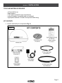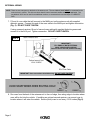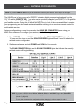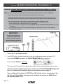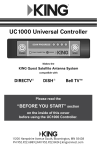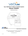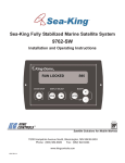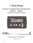
1
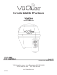
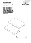
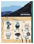
Automatic Satellite TV Antenna
KD1500
Owner’s Manual
11200 Hampshire Avenue South, Bloomington, MN 55438
PH 952.922.6889 || FAX 952.922.8424 || kingcontrols.com
IMPORTANT!
The satellite TV market is expanding and changing. The information in this manual was accurate at the time of
printing. If your KING Rover™ Satellite Antenna does not operate as outlined in this manual, please call KING
at (952) 922-6889 or visit our website at www.kingcontrols.com. KING is not responsible for changes outside
of its control.
Please read this entire manual before installing and using your new antenna.
IMPORTANT! DISH® CUSTOMERS WITH HD SOLO RECEIVERS ONLY!
If you have a DISH model ViP211z, ViP211k, ViP211 or 411 single tuner HD receiver, you can use the DISH
Tailgater® user interface on your receiver (see Sections 3 and 7).
PRODUCT REGISTRATION
To provide on-going technical support and to better facilitate warranty processing,
please register your product at www.kingcontrols.com/products/productregistration/.
TABLE OF CONTENTS
SectionContents
Page
1.INTRODUCTION . . . . . . . . . . . . . . . . . . . . . . . . . . . . . . . . . . . . . . . . . . . . . . . . . . . . . . . . 2
2.INSTALLATION . . . . . . . . . . . . . . . . . . . . . . . . . . . . . . . . . . . . . . . . . . . . . . . . . . . . . . . . 3-9
3.
ANTENNA CONFIGURATION . . . . . . . . . . . . . . . . . . . . . . . . . . . . . . . . . . . . . . . . . . . 10-11
4.
RECEIVER CONFIGURATION - DISH AND BELLTM TV . . . . . . . . . . . . . . . . . . . . . . . 12-14
5.OPERATION . . . . . . . . . . . . . . . . . . . . . . . . . . . . . . . . . . . . . . . . . . . . . . . . . . . . . . . . 16-17
6.
SECOND RECEIVER OPERATION - DISH AND BELL TV . . . . . . . . . . . . . . . . . . . . 18-19
7.
TAILGATER MODE . . . . . . . . . . . . . . . . . . . . . . . . . . . . . . . . . . . . . . . . . . . . . . . . . . . 20-29
8.TROUBLESHOOTING . . . . . . . . . . . . . . . . . . . . . . . . . . . . . . . . . . . . . . . . . . . . . . . . . . 30
9.MAINTENANCE . . . . . . . . . . . . . . . . . . . . . . . . . . . . . . . . . . . . . . . . . . . . . . . . . . . . . . . 31
10.
LIMITED WARRANTY . . . . . . . . . . . . . . . . . . . . . . . . . . . . . . . . . . . . . . . . . . . . . . . . . . . 32
Bell TV is an official trademark of Bell Canada.
DIRECTV is a registered trademark of DIRECTV, Inc.
DISH and Tailgater are registered trademarks of DISH Network L.L.C.
Rover is a registered trademark of Electronic Controlled Systems, Inc.
KING and KING Rover are trademarks of Electronic Controlled Systems, Inc.
Page 1
Section 1
INTRODUCTION
The KING Rover Satellite System includes 3 main components (Fig. 1).
Antenna Unit Located on the roof of the vehicle. The satellite dish and electronics are
covered by a protective dome that keeps operational components free from
the elements.
ControllerLocated in the vehicle. Activates the search mode and provides limited
diagnostic functions using the controller’s lights.
Power SupplyLocated in the vehicle. Supplies proper operating voltage to the KING
Rover Controller. (The antenna unit draws power thru the coax from
the receiver.)
NOTE: A TV, satellite receiver, and program subscription are also required for satellite TV viewing (sold separately).
FIG. 1
NOTE: If your receiver supports
an over-the-air antenna, you can
use a KING JACK antenna for
free over-the-air broadcasts.
NOTE: The KING Rover will not work with DIRECTV® SWM only
receivers. It will not receive channels broadcast from
DIRECTV’s Ka band satellites at 99° and 103°.
Do not use dual tuner receivers or receivers with built-in
recorders if your programming is broadcast from more than
one satellite.
NOTE: Overview only. See connection
diagram in INSTALLATION
section for detailed information.
Page 2
ell TV: You may experience difficulty receiving your
B
programming more than approximately 100 miles south of
the Canadian/US border.
Section 2
INSTALLATION
TOOLS AND MATERIALS REQUIRED
• drill and drill bit set
• tape measure
• 7/16” open end wrench (coax connections)
• adhesive sealant (compatible with roof material)
• appropriate fasteners to install all components and wiring
KIT CONTENTS
1. Unpack and identify all components (Fig. 2).
FIG. 2
Page 3
NOTE: Many RVs are pre-wired for satellite with RG-6 coax cable. Contact the manufacturer of your RV or your local
dealer to verify where this cable is located.
If pre-wired, run the existing coax cable from the pre-wire location in the roof to the antenna unit. When
choosing the antenna unit location, make sure the pre-wiring will reach the antenna unit.
Make all connections, properly route and fasten wiring to roof, and completely waterproof entry hole with the
cable entry cover as shown in this section. You may still run a second coax to the rear of the vehicle for an
optional second receiver.
ANTENNA UNIT LOCATION
2.Select an area on the roof for the antenna unit and the location where the wiring will enter the
vehicle through the roof to the satellite receiver inside using the following criteria:
a)A shorter distance between the antenna unit and the satellite receiver is most desirable.
b)The antenna unit requires a 28 inch diameter mounting area.
c)The antenna unit should be mounted on the centerline of the vehicle.
d)There must be no “line of sight” obstructions. Air conditioning units, other antennas, and
storage areas that are too close to the antenna unit may prevent the satellite signal from
reaching the antenna unit (Fig. 3).
FIG. 3
10”
APPROXIMATE
MINIMUM DISTANCE TO
EDGE OF ANTENNA UNIT
8”
11”
10”
12”
12”
13”
14”
14”
16”
15”
18”
16”
20”
HEIGHT OF
OBSTRUCTION
Page 4
ANTENNA UNIT INSTALLATION
IMPORTANT! Cable connections must ALWAYS be positioned facing the rear of vehicle.
3.Place antenna unit on installation location chosen using the criteria discussed on the previous
page. Cable connections must be positioned facing rear of vehicle.
4.The antenna unit must be positioned so that both mounting feet on each side of the vehicle are
equal distances from the roof edge. This should be checked by measuring the distance from
each foot to the roof edge. Confirm that these measurements are equal (Fig. 4).
FIG. 4
IMPORTANT!
Cable connections
must always face
REAR of vehicle.
IMPORTANT! T
he antenna unit should never be mounted so that it is tilted
more than two degrees in any direction.
NOTE: The installer is responsible for determining the most appropriate fastener to secure the antenna unit to the roof.
Depending on the roof material, fasteners such as lag screws, well nuts, sheet metal screws, toggle bolts and T
anchors may be used, and should always be used in combination with a roof compatible sealant.
IMPORTANT! The installer is responsible for weatherproofing all holes with sealant.
5.Mount the antenna unit. Use the pre-drilled holes in the mounting feet as a guide to install the
fasteners into the roof. Use additional fasteners whenever necessary.
6. Test that the antenna unit is secure by pulling upward from each foot location.
Page 5
EXTERNAL WIRING
NOTE: There are two coax ports on the back of the antenna unit. The one labeled “MAIN” MUST be connected to the
main receiver in vehicle. This is the receiver that will control automatic satellite switching if applicable. The
one labeled “AUX” can be used for an additional receiver, or connected to the second input on a DIRECTV
DVR.
7.Fill end of coax cable that will connect to the MAIN port on the antenna unit with supplied
dielectric grease. Connect this end of the coax cable to the MAIN port and tighten connection
(Fig. 5). DO NOT OVER TIGHTEN.
If using a second receiver, fill end of second coax cable with supplied dielectric grease and
connect it to the AUX port. Tighten connection. DO NOT OVER TIGHTEN.
FIG. 5
IMPORTANT!
FILL ENDS OF BOTH EXTERNAL
COAX CABLES WITH GREASE.
Failure to do so will void product warranty.
IMPORTANT! Coax connections should be snug. DO NOT OVER TIGHTEN!
8.Run coax from the back of the antenna unit to the roof edge, then along edge to location where
coax will be fed into the vehicle. If installing an optional second receiver, run second coax to
location where it will enter the vehicle. Secure (both) coax to roof every 12-18 inches (Fig. 6).
Page 6
IMPORTANT! Installer is responsible for determining proper roof compatible fasteners for cable entry cover.
Roof hole for wiring must be sealed so it is completely waterproof. Mounting holes, perimeter of
cable entry cover and cable opening of cable entry cover must be sealed so they are completely
waterproof. SEALANT MUST BE ROOF COMPATIBLE.
9.Drill 3/4” hole through the roof and into the cabinet where receiver is stored. Feed coax down
through hole. Seal opening with roof compatible sealant so that it is completely waterproof
(inside and outside of the 3/4” hole). Repeat for second coax if present.
10.Fasten cable entry cover to roof. Seal mounting holes, perimeter of cover and cable opening
so they are completely waterproof.
FIG. 6
IMPORTANT!
Sealant must be roof compatible.
11. Remove blue protective sheet and red “position to rear” sticker from the antenna unit.
Page 7
INTERNAL WIRING
12.Make the connections IN THE ORDER SHOWN on the next page.
13.After internal connections are made, go to ANTENNA CONFIGURATION on page 10.
NOTE: Do not use dual tuner receivers or receivers with built-in recorders when satellite service is broadcast from
more than one satellite.
NOTE FOR DISH SERVICES: F
or automatic satellite switching, KING recommends using a DISH model 311 receiver
for DISH SD.
Page 8
A
B
IMPORTANT! DISH and Bell TV Subscribers:
Do not connect 2nd receiver at this time.
C
D
IMPORTANT! DISH and Bell TV Subscribers:
Do not connect 2nd receiver at this time.
E
Page 9
Section 3
ANTENNA CONFIGURATION
NOTE: If you have DIRECTV SD service you do not need to configure your antenna. Go to step 5 on next page.
The KING Rover is factory pre-set for DIRECTV standard digital programming broadcast from the
101° W satellite (DIRECTV SD). If you also receive your local channels from DIRECTV’s 119 satellite
or if you subscribe to DISH or Bell TV programming, you must configure the antenna to work with
your satellite service. Doing this will allow the KING Rover to lock on the correct satellites to receive
your programming and also enable automatic satellite switching via the receiver’s remote control for
multi-satellite service.
Antenna configuration is a one time procedure that MUST BE COMPLETED before using your
KING Rover antenna. To configure your antenna, do the following:
1.Press POWER to turn on KING Rover controller. The COAX CONNECTION light will flash
10 times and then turn on, and the SCAN PROGRESS lights will flash 3 times to indicate the
selected service configuration.
2.Simultaneously press and hold POWER and SCAN for five seconds.
The COAX CONNECTION light and the SCAN PROGRESS lights that indicate the currently
selected service will begin flashing.
NOTE: If you have a DISH receiver ViP211z, ViP211k, ViP211 or 411, FIRST choose the TAILGATER
MODE setting as instructed on these two pages, and then continue with Tailgater Mode
(Section 7, page 20).
To verify the current service configuration without changing it, perform steps 1, 2 and 4.
Page 10
3. Press SCAN repeatedly to scroll thru the available service provider options.
4.When the correct lights turn on to show your desired satellite configuration, simultaneously
press and hold POWER and SCAN for five seconds.
All lights will turn off except for the COAX CONNECTION light.
5. Locate your service below and follow the instructions:
DIRECTV subscribers:
NOTE: The KING Rover will not work with SWM only receivers. Your local channels may not be available when
traveling outside your home area.
DIRECTV SD
If you have a newer receiver or current software, choose the following dish
configuration settings (do this through the receiver’s satellite set-up menu screens):
Switch Type: 02:Multiswitch
Dish Type: 01: 18” Round
(If you have an older receiver, choose: round dish-1 satellite.)
DIRECTV SD with Locals
If you have a newer receiver or current software, choose the following dish
configuration settings (do this through the receiver’s satellite set-up menu screens):
Switch Type: 02:Multiswitch
Dish Type: 02: 3-LNB (18 x 20”)
(If you have an older receiver, choose: oval dish-2 satellites.)
After setting your dish for either service as described above . . . . . . . . . . . . . go to page 16.
DISH
subscribers with the following receivers:
ViP211z
•
ViP211k
•
ViP211
•
411
and who chose TAILGATER MODE on the previous page . . . . . . . . . . . . . . . go to page 20.
NOTE: Your local channels may not be available when traveling outside your home area.
All other DISH and Bell TV subscribers:
After you have successfully configured your antenna, you must
configure your receiver for mobile use by running a check switch test . . . . . . go to page 12.
NOTE: Dual tuner receivers or receivers with built-in recorders are not recommended and will not have full functionality
when used with the KING Rover antenna. Your local channels may not be available when traveling outside
your home area.
Page 11
Section 4
RECEIVER CONFIGURATION - DISH AND BELL TV
IMPORTANT! Y
OU MUST HAVE COMPLETED THE ANTENNA CONFIGURATION ON PAGES 10-11 BEFORE
CONTINUING BELOW.
NOTE: For automatic satellite switching, KING recommends using a DISH model 311 receiver for DISH SD.
If you do not have a clear view of the satellites, the switch will not load correctly.
The SW21 and SW64 switches are a receiver software configuration that is loaded into the receiver after
successfully running a check switch test with the dish locked on and configured for the appropriate service.
This one time procedure will not need to be repeated after successful installation, unless:
a) check switch test is run again while the receiver is connected to a home dish system.
b) check switch test is run when the receiver is not connected.
c) you travel outside the coverage area of either DISH SD and HD or DISH SD and HD Alternate and switch
to the other.
d) you are parked in an area where the selected satellites are blocked, but are able to select alternate
satellites and get signal.
IMPORTANT!
The antenna unit requires a
“direct line of sight” to the
satellites for signal reception.
Any tall objects can block the
signal from reaching the antenna.
1. Turn on the TV and satellite receiver.
2.Your KING Rover controller should be on from the configuration process on pages 10-11.
If not, press POWER and wait for the COAX CONNECTION light to remain on.
Press and hold SCAN for 3 seconds.
The antenna will locate all of the appropriate satellites before completing the search process.
After the antenna acquisition process is complete, specific SCAN PROGRESS lights will
turn on to indicate which satellites have been found (see chart on page 17).
If you configured the antenna for DISH SD and HD and the antenna cannot acquire the
110, 119, and 129 satellites, you may need to configure the antenna for DISH SD and
HD Alternate (pages 10-11).
Page 12
3. On the receiver remote, press MENU, 6, 1, 1.
4.Highlight “Check Switch.”
Press SELECT on your remote.
NOTE: Some receivers may prompt you to select
“Check Switch” a second time to initiate
the test.
Screen graphics may vary.
5.Make sure “SuperDISH” and “Alternate” boxes
are NOT selected.
NOTE: Not all receivers will display a screen with
options that include “SuperDISH” and
“Alternate” boxes.
6.Highlight “Test.”
Press SELECT on your remote.
The receiver will perform a check switch test, during which time the antenna will periodically
move back and forth between satellites. This process will take several minutes.
7.When test is complete, a screen similar to one below or on the next page should appear.
After screen verification, continue with check switch test procedure on next page.
Because receivers are always changing, screen graphics may vary.
DISH SD
MUST SHOW
“SW21”
NO “X”s
Page 13
DISH SD and HD
DISH SD and HD Alternate
NO “X”s
MUST SHOW
“SW64”
Bell TV SD
“NO SWITCH
DETECTED”
or
“INSTALLED
DEVICE
UNKNOWN”
or
similar
Bell TV SD and HD
MUST SHOW
“SW21”
NO “X”s
If the indicated results are not obtained, go back to Step 3 and run test again. Contact KING if
the check switch fails to load after 4 attempts.
8.When the installation summary shows the successful check switch test results, save the
settings, exit to the main menu screen and wait for programming to download.
9.
DISH SD and HD and DISH SD and HD Alternate only: Verify that your saved settings show
your desired satellite trio: 61.5, 110, 119 or 110, 119, 129. To switch trios, see pages 10-11.
Configuration is complete. Go to page 16, OPERATION.
Page 14
This page intentionally left blank.
Page 15
Section 5
OPERATION
IMPORTANT: If you chose Tailgater Mode in the antenna configuration section, DO NOT use the instructions
on this page. Go to the Tailgater Mode instructions on page 20.
Your local channels may not be available when traveling outside your home area.
The KING Rover will not receive channels broadcast from DIRECTV’s Ka band satellites at 99°
and 103°.
IMPORTANT!
The antenna unit requires a “direct
line of sight” to the satellites for
signal reception.
Any tall objects can block the
signal from reaching the antenna.
If you chose TAILGATER MODE, do not use these instructions.
Go to page 20 instead.
POWER UP
1.Make sure all connections are made as shown on page 9.
2.Press POWER to turn on KING Rover controller.
• All lights will turn on briefly.
• The COAX CONNECTION light will flash 10 times and the SCAN PROGRESS lights will
flash 3 times to indicate the currently selected service configuration and then turn off.
• If the unit is operating properly, the COAX CONNECTION light will remain on and all other
lights will turn off.
3. Turn the TV and satellite receiver on.
• Antenna is now ready to scan for satellites. Go to next page.
Page 16
SCAN FOR SATELLITES
1. Press and hold SCAN for 3 seconds.
• The antenna will scan for the selected satellites. The four SCAN PROGRESS lights will
cycle on and off to indicate a scan is in progress.
• As satellites are located, the corresponding SCAN PROGRESS lights will turn on (see
below).
• When scan is complete, the appropriate lights will turn on to show which satellites were
found.
• Wait for the program guide to download and then select your desired channel.
Use this chart to determine which satellites have been found.
NOTE: The order of the lights corresponds to the order of the satellites listed.
Example for DISH SD: The 110 satellite corresponds to Light 1, and the 119
satellite corresponds to light 2.
NOTE: If you move the vehicle, you will have to re-acquire the satellites by repeating the scan process. The KING
Rover will go into “sleep mode” after 15 minutes and the COAX CONNECTION light will dim. Press POWER to
wake unit up if necessary, i. e. the unit is in sleep mode, you move the vehicle, and wish to rescan for satellites.
To turn the unit off at any time, press POWER for 3 seconds.
DISH AND BELL TV SUBSCRIBERS: If you are using a second receiver, see SECOND RECEIVER OPERATION DISH AND BELL TV on page 18.
Page 17
Section 6
SECOND RECEIVER OPERATION - DISH AND BELL TV
INITIAL SETUP FOR SECOND RECEIVER
1.With the antenna locked on the satellite
and the second receiver connected to the
antenna unit’s AUX port coax, use your
DISH remote control and press MENU, 6, 1, 1
to display the Point Dish screen.
2.Use the arrow buttons on the remote
to highlight “Check Switch.”
Antenna locked on
and
receiver connected!
Press SELECT on your remote.
3.Verify “SuperDISH” and “Alternate”
are not selected.
Verify “Test” is highlighted.
Press SELECT on your remote.
4.When test is complete, highlight “Save.”
Press SELECT on your remote.
See the next page for downloading programming to the second receiver.
Page 18
DOWNLOADING PROGRAMMING TO THE SECOND RECEIVER
1.After completing the steps on the previous page, re-set the second receiver by pressing the
POWER button on the front panel for 10 seconds. The TV picture will go away and should
reappear within two minutes.
The receiver will then download the program guide to show only the channels available on the
current satellite as determined by the channel selected on the main receiver. Downloading the
new program guide can take up to five minutes to complete.
The channels available on the second receiver are determined by the channel/satellite selected on
the main receiver. For example, if you select a channel on the main receiver that is broadcast from
the 119 satellite, then the second receiver will be able to view any channel broadcast from the 119
satellite.
If you switch channels on the main receiver to one that is broadcast from a different satellite, (i.e. your
channel was broadcast from satellite 119 but your new channel is broadcast from the 110 or 129),
the antenna will automatically switch to the new satellite and programming will be lost on the second
receiver until you either:
• Select a channel on the main receiver that is broadcast from the previous satellite (satellite
119 in this example).
(or)
• Reset the second receiver to download the program guide for the newly selected satellite
(satellite 110 or 129 in this example).
NOTE: If you choose a channel on the main TV that causes the antenna to switch satellites, you may have to run a
check switch on the second receiver.
Page 19
Section 7
TAILGATER MODE
IMPORTANT! You must have chosen Tailgater Mode on pages 10-11.
Your local channels may not be available when traveling outside your home area.
IMPORTANT!
The antenna unit requires a
“direct line of sight” to the
satellites for signal reception.
Any tall objects can block the
signal from reaching the antenna.
If your receiver is NEW AND UNACTIVATED, START HERE.
If not, go to page 26.
1.If your KING Rover controller is not on, press POWER and wait for the COAX CONNECTION
light to remain on.
2.Plug your receiver and TV into a 110 volt AC power source.
The green power light on your receiver should illuminate or begin cycling on and off.
Wait for the green light to turn solid. This may take up to two minutes.
If it does not turn solid, power on your receiver using the front panel POWER button.
(On ViP211z models, this is located behind the door panel.)
3.Plug in and turn on your TV.
In your TV’s input selection menu, choose the input that matches the connection from your
receiver (example: if using an HDMI cable from your receiver, choose the HDMI input on your
TV). See your TV owner’s manual for details.
Page 20
4.Point your receiver’s remote at the front of
the receiver and press SAT.
Press RECORD.
When a number appears in the box,
verify “Continue” is highlighted.
Press SELECT on your remote.
The Portable Antenna Setup screen
will display.
5.Use the arrow buttons on your remote to
highlight the letter group that includes the
first letter of the state you are currently in.
Press SELECT.
Page 21
6.Highlight the state you are currently in
from the state menu.
Press SELECT.
7.Verify “Scan” is highlighted.
Press SELECT.
The scan will begin and may take up to
several minutes to complete.
The receiver will update software for
DISH programming This step may take
20-25 minutes.
Page 22
8.The receiver will reset and the Mobile
Antenna Setup Screen will appear.
Choose your location again and
initiate a second scan.
The unit will scan a second time.
When the scan is complete, the
“Acquiring Signal” message will display.
Acquiring the signal may take up to 5
minutes to complete.
Page 23
9.After your receiver has acquired the signal,
it is ready to be activated. If your receiver
packaging has a specific phone number
displayed, be sure to call this number to
activate your service. Otherwise, call
1-800-333-DISH (3474) to activate.
After your receiver is activated,
the electronic program guide will download.
This may take up to 5 minutes to complete
(potentially longer if an external hard drive
is connected).
This completes the setup for new receivers.
From now on, use the standard operation procedure starting on page 26.
Page 24
This page intentionally left blank.
Page 25
STANDARD TAILGATER OPERATION
IMPORTANT! You must have chosen Tailgater Mode on pages 10-11.
Your local channels may not be available when traveling outside your home area.
IMPORTANT!
The antenna unit requires a
“direct line of sight” to the
satellites for signal reception.
Any tall objects can block the
signal from reaching the antenna.
If your receiver is NEW AND UNACTIVATED, start on page 20.
1.If your KING Rover controller is not on, press POWER and wait for the COAX CONNECTION
light to remain on.
2.Plug your receiver and TV into a 110 volt AC power source.
The green power light on your receiver should illuminate or begin cycling on and off.
Wait for the green light to turn solid. This may take up to two minutes.
If it does not turn solid, power on your receiver using the front panel POWER button.
(On ViP211z models, this is located behind the door panel.)
3.Plug in and turn on your TV.
In your TV’s input selection menu, choose the input that matches the connection from your
receiver (example: if using an HDMI cable from your receiver, choose the HDMI input on your
TV). See your TV owner’s manual for details.
Page 26
The Mobile Antenna Setup screen will be displayed on your TV.
NOTE: If the Mobile Antenna Setup screen
does not display, press MENU, 6, 1, 1
on your DISH remote.
Highlight “Check Switch.”
Press SELECT on your remote.
The Mobile Antenna Setup screen
should now display.
4.Use the arrow buttons on your remote to
highlight the letter group that includes the
first letter of the state you are currently in.
Press SELECT on your remote.
Page 27
5.Highlight the state you are currently in
from the state menu.
Press SELECT.
6.Verify “Scan” is highlighted.
Press SELECT.
The scan will begin and may take up to
several minutes to complete.
This screen will display during the scan.
7.When the scan is complete, the
“Acquiring Signal” message will display.
Acquiring the signal may take up to 5
minutes to complete.
Page 28
8.After your receiver has acquired the signal,
the electronic program guide will download.
This may take up to 5 minutes to complete
(potentially longer if an external hard drive
is connected).
OPERATING NOTES
To turn the unit off at any time press POWER for 3 seconds.
If your system is inactive for an extended period of time, you may need to call DISH Customer Service at
1-800-333-DISH (3474) to re-authorize your receiver. You can view your programming when your receiver has been
re-authorized and the guide has finished downloading.
If you move the vehicle, you will need to repeat the scan process to re-acquire the satellites and restore programming.
When in the northeastern United States, television programming from the 129 satellite may not be available, so you
may wish to configure your antenna for DISH SD and HD Alternate. Make sure the controller is turned off, and then
use the procedure found in the ANTENNA CONFIGURATION section (pages 10-11). When you leave the northeastern
US you will need to configure the antenna for Tailgater Mode once again.
Page 29
Section 8
SYMPTOM
No lights turn on.
TROUBLESHOOTING
POSSIBLE CAUSE
No power to controller.
COURSE OF ACTION
Verify power supply is properly
connected to KING Rover
controller.
Verify power supply is plugged
into a 110-120 VAC power
source.
ERROR light and all 4 SCAN
lights flash slowly.
No satellites found.
Line of sight obstructions. Move
vehicle so unit has a better view
of southern sky and rescan.
Inclement weather can
occasionally cause loss of
signal. Wait till weather
improves and rescan.
If problem persists, call KING
Service at (952) 922-6889.
ERROR light and COAX
CONNECTION light both flash
quickly.
Scan is not complete after 15
minutes.
Page 30
Coax between antenna unit
and KING Rover controller not
connected.
Connect coax between antenna
unit and KING Rover controller.
Coax from KING Rover
controller connected to wrong
port (AUX) on antenna unit.
Connect coax from KING Rover
controller to MAIN port on
antenna unit.
Coax between antenna unit
and KING Rover controller
faulty.
Replace coax (KC #100292-35).
Coax between main circuit
board and output port on
antenna unit faulty.
Call KING Service at
(952) 922-6889.
Antenna is not moving.
Call KING Service at
(952) 922-6889.
Section 9
MAINTENANCE
KING Rover Satellite Systems are designed to be maintenance and trouble free.
For optimum performance, keep the dome clean from dirt, bugs, and other debris. Periodic washing
of the dome with mild soap and water is recommended.
IMPORTANT! Do not power wash the KING Rover.
If you plan on storing your vehicle for long periods of time, it is recommended that the system be put
through a search procedure on a quarterly basis to keep all moving parts in good working order.
If you have any comments or questions, please contact the KING Service Department at (952) 9226889, or via email at [email protected].
Rain Fade
Rain or dew on the dome can cause signal interference and make the digital picture freeze, pixelate
or go out altogether. This loss of signal is commonly referred to as “rain fade” and is caused by the
combination of water in the atmosphere and water on the dome surface.
To minimize this issue and eliminate the effects of water on the dome, apply KING Dome Magic® rain
fade solution to the dome. This will prevent water from adhering to the dome surface and blocking
the signal. For additional details on Dome Magic® rain fade solution please contact an authorized
dealer or call KING at (952) 922-6889.
Single Application Packet #1830-SP
Spray Can #1830
NOTE: Dome Magic® will discolor black domes or domes painted a dark color.
Page 31
Section 10
LIMITED WARRANTY
Every new KING Rover Satellite System is thoroughly inspected and tested before leaving the factory, and is covered by the following
two year parts and one year labor limited warranty from the date of original purchase:
• Two year parts warranty: The customer is not responsible for the cost of replacement parts if the original part is determined to
be defective under the terms of the warranty. The customer is responsible for the cost of replacement parts after two years.
• One year labor warranty: The customer is not responsible for labor costs to repair unit if unit falls under the terms of the
warranty. Any warranty labor outside of that performed at the factory is not covered unless the product has been installed by an
authorized dealer/installer or OEM manufacturer. The customer is responsible for all labor costs after one year.
Should any trouble develop during the warranty period, contact KING. You must contact KING before the warranty period expires. The
customer must supply proof of purchase (such as a dated sales receipt) when requesting warranty service. If customer cannot supply
proof of purchase, warranty period shall start 30 days after date of manufacture.
Only KING and certified dealers are authorized to perform warranty evaluations and repairs. Depending upon the problem, KING may
authorize the dealer to perform the necessary repairs, or may have the unit returned to KING for repairs.
A certified dealer must not perform any repair without first contacting KING for a Service Order Number. KING will advise the dealer on
how to proceed with any repairs.
If it is determined that the unit needs to be returned to KING, customer must return COMPLETE product, freight prepaid, to:
KING, 11200 Hampshire Avenue South, Bloomington, MN 55438-2453.
If inspection shows the trouble is caused by defective workmanship or material, KING will repair (or at its option, replace) without
charge.
When returning product, KING will supply an RMA number (Return Merchandise Authorization). This number must be clearly written
on the box. Failure to clearly write RMA number on box may result in delays in processing claim. Along with product, customer should
include in the box: his/her name, address, daytime phone number, proof of purchase and description of the problem.
This warranty does not cover installation and external wiring, or remanufactured units. This warranty is not transferable from the
original owner.
Due to the expanding and changing TV market, KING cannot be held responsible for changes made to satellite services. Software
updates to address such issues are not covered under warranty.
This warranty also does not apply where:
• The product has been abused, misused, improperly installed or improperly maintained.
• Repairs have been made or attempted by others that are not certified by KING to do such repairs.
• Repairs are required because of normal wear and tear.
• Alterations have been made to the product.
• The dome has been removed without authorization.
• Supplied grease not used in the external coax connections as specified in the instructions.
• Damage has been caused by power washing.
• Circumstances beyond the control of KING cause the product to no longer operate correctly.
• Customer is not the original owner.
In no event shall KING be liable for any indirect, incidental, or consequential damages from the sale or use of the product.
This disclaimer applies both during and after the term of the warranty.
KING disclaims liability for any implied warranties, including implied warranties of “merchantability” and “fitness for a
specific purpose,” after the one year term of this warranty.
This warranty gives you specific legal rights, and you may also have other rights, which vary from state to state. Some states do not
allow the exclusion or limitation of incidental or consequential damages, so the above limitation or exclusion may not apply to you.
Some states do not allow limitations on how long an implied warranty lasts, so the above limitation may not apply to you.
Page 32
11200 Hampshire Avenue South, Bloomington, MN 55438
PH 952.922.6889 || FAX 952.922.8424 || kingcontrols.com
21443 Rev E