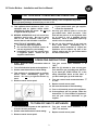
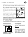
1
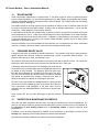
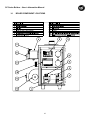
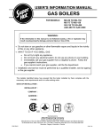
USER'S INFORMATION MANUAL
SC GAS BOILERS
FOR MODELS:
SC-35 TO SC-280
WARNING:
If the information in this manual is not followed exactly, a fire or explosion may
result causing property damage, personal injury or loss of life.
→ Do not store or use gasoline or other flammable vapors and liquids in the vicinity
of this or any other appliance.
→ WHAT TO DO IF YOU SMELL GAS
•
•
•
•
Do not try to light any appliance.
Do not touch any electrical switch; do not use any phone in your building.
Immediately call your gas supplier from a neighbor’s phone. Follow the
gas supplier’s instructions.
If you cannot reach your gas supplier, call the fire department.
→ Installation and service must be performed by a qualified installer, service agency
or the gas supplier.
The installer identified below has ensured that the boiler installed by them complies with the
necessary code requirements and is in safe working order.
DATE OF INSTALLATION :
INSTALLED BY :
COMPANY :
ADDRESS :
PHONE :
Manufactured by
Allied Engineering Company
Division of E-Z-Rect Manufacturing Ltd.
Manufacturers of Gas and Electric Boilers, Stainless Steel Tanks, Heat Exchangers and Electric Boosters.
94 Riverside Drive, North Vancouver, B.C. V7H 2M6 • Telephone (604) 929-1214 • FAX (604) 929-5184
Branches: Calgary • Edmonton • Toronto
PN9181263
PRICE: $6
SC Series Boilers – Installation and Service Manual
1
ABOUT OUR MANUALS
Your Super Hot boiler has been provided with two manuals:
•
User's Information Manual - This manual is intended for the owner or user of the boiler and provides
information on routine operation and maintenance, and emergency shutdown.
•
Installation and Service Manual - This manual must only be used by a qualified heating installer,
service technician or gas supplier. Installation or service by anyone unqualified to do so may
result in severe personal injury, death or substantial property damage.
Both manuals should be kept in the envelope provided and affixed adjacent to the boiler so that they are
readily available for future reference.
2
LIGHTING INSTRUCTIONS
This boiler is always equipped with an ignition device which automatically and directly lights the main
burners (there is no pilot burner).
There are two possible ignition systems:
1. direct spark ignition with combination gas valve (equipped with gas control knob) and module.
2. hot surface ignition with combination gas valve (equipped with gas control knob) and module.
The lighting instructions shown in this section apply to both ignition systems. In addition, the lighting
instructions have been printed on a label attached to the boiler. If you are unsure which type of gas valve
or ignition system your boiler is equipped with, check the wiring diagram sticker on the boiler or contact
the factory.
WARNING
Should boiler overheat, or the gas supply fail to shut off, do not turn off or disconnect the
electrical supply to the circulating pump. Instead, shut off the gas supply at a location external
to the boiler.
2
SC Series Boilers – Installation and Service Manual
FOR YOUR SAFETY READ BEFORE OPERATING
WARNING: If you do not follow these instructions exactly, a fire or explosion may result
causing property damage, personal injury or loss of life.
A. This appliance does not have a pilot. It is
• If you cannot reach your gas supplier,
equipped with an ignition device which
call the fire department.
automatically lights the burner. Do not try C. Use only your hand to push in or turn the
to light the burner by hand.
gas control knob. Never use tools. If the
B. BEFORE OPERATING smell all around the
knob will not push in or turn by hand, don't
appliance area for gas. Be sure to smell
try to repair it, call a qualified service
next to the floor because some gas is
technician. Force or attempted repair may
heavier than air and will settle on the floor.
result in a fire or explosion.
WHAT TO DO IF YOU SMELL GAS
D. Do not use this appliance if any part has
• Do not try to light any appliance
been under water.
Immediately call a
• Do not touch any electrical switch; do
qualified service technician to inspect the
not use any phone in your building.
appliance and to replace any part of the
• Immediately call your gas supplier from
control system and any gas control which
a neighbor's phone. Follow the gas
has been under water.
supplier's instructions.
OPERATING INSTRUCTIONS
1. STOP! Read the safety information above 6. Turn gas control knob clockwise 3 to
on this label.
"OFF".
2. Turn off all electrical power to the appliance. 7. Wait five (5) minutes to clear out any gas.
Then smell for gas, including near the floor.
If you smell gas, STOP! Follow "B" in the
safety information above on this label. If
you don't smell gas, go to the next step.
3. Set the room thermostat to lowest setting.
4. This appliance is equipped with an ignition
device which automatically lights the
burner. Do not try to light the burner by
hand.
8. Turn gas control knob counterclockwise
to "ON".
5. Remove control access panel.
4
9. Replace control access panel.
10. Set room thermostat to desired setting.
11. Turn on all electrical power to the appliance.
12. If the appliance will not operate, follow the
instructions "To Turn Off Gas To Appliance"
and call your service technician or gas
supplier.
TO TURN OFF GAS TO APPLIANCE
1. Turn off all electrical power to the appliance 4. Turn gas control knob clockwise
if service is to be performed.
"OFF". Do not force.
2. Set the room thermostat to lowest setting.
5. Replace control access panel.
3. Remove control access panel.
3
3
to
SC Series Boilers – User’s Information Manual
3
AREA AROUND BOILER
Keep boiler area clear and free from combustible materials, gasoline and other flammable vapors and
liquids.
Do not store anything against the boiler or allow dirt or debris to accumulate in the area immediately
surrounding the boiler. It is unsafe for the flow of supply and exhaust air to be obstructed in any way.
Should your boiler be subjected to fire, flood or some other unusual condition, turn off all gas and
electrical supply. If you are unable to turn off the gas, call your gas company or gas supplier at once. Do
not put the boiler in operation again until it has been ascertained by a qualified agency that the controls
are functioning correctly. The installer should always clearly identify the emergency shut-off devices and
make the owner aware of their location and method of operation.
WARNING
Do not use this boiler if any part has been under water. Immediately call a qualified service
technician to inspect the boiler and to replace any part of the control system and any gas
control which has been under water.
4
CHECK FOR GAS LEAKS
To identify gas leaks, smell for gas around boiler area and gas piping connections. To check a specific
area, including the manifold joint connected to the gas valve outlet, for leakage, spray a mixture of soap
and water onto the suspected area – active bubbling indicates a gas leak. DO NOT TEST FOR LEAKS
WITH AN OPEN FLAME.
Propane or liquefied petroleum (LP) is heavier than air may collect or "pool" in a low area in the event of a
leak from defective equipment. This gas may then ignite resulting in a fire or explosion. Smell near to the
ground and low points when checking for propane gas leaks.
If you smell gas, STOP! Follow "A" in the safety instructions in Section 2. Gas leaks must be repaired
immediately.
5
CORROSIVE ATMOSPHERES
If a gas boiler is to be installed near a corrosive or potentially corrosive air supply, the boiler should be
isolated from it and outside air should be supplied.
Chemical vapors from products containing chlorine or fluorine must be avoided. Even though these
chemicals may be safe to breathe, corrosive substances can become liberated when passed through a
gas flame. Even at low concentrations, these chemicals can significantly contaminate the air supply and
shorten the life of any gas-fired appliance. The following is a list of some of the products which should be
avoided:
•
bleaches and chlorinated cleaning products
•
paints and sprays
•
water softeners (calcium or sodium chloride)
•
leaking refrigeration equipment
•
freon from common aerosol dispensers
These chemicals are especially commons near swimming pools, beauty shops, dry cleaning
establishments, laundry areas, workshops, and garages. The warranty is void when failure is due to
corrosion.
4
SC Series Boilers – User’s Information Manual
6
AIR SUPPLY FOR COMBUSTION AND VENTILATION
A sufficient air supply MUST be provided to this boiler. Air openings to the boiler room provide the air for
combustion, flue gas dilution and ventilation and are always required, regardless whether the air is taken
from inside or outside. The air opening size and location, as well as exhaust venting considerations must
conform to the applicable codes. If any alteration of the air supply and venting system is required, contact
a qualified service agency.
The boiler room must never be under a negative pressure. Air openings should be sized by your installer
not only to the dimensions required for the total input of all fuel-fired appliances in the boiler space, but
also to handle the air movement rate of any exhaust fans or air movers using air from the building or
space.
Make sure the venting terminations are always kept clear of obstructions (i.e. snow, ice, etc.). Louvers
and grilles used in your air supply and ventilation system should be checked regularly and cleaned of any
dust, dirt, or debris which will block proper air flow.
7
CHECK CONDENSATE TUBE
All boiler with vertical venting installations require a condensate drain and drain trap. Do not operate the
boiler without installing this trap and filling with water.
The condensate drain should be installed as close to the boiler as possible and must be equipped with a
drain trap. The drain tap should be formed by attaching 3/8” I.D. high temperature tubing, such as
silicone, to the drain assembly, making a loop of approximately 4” diameter and securing it with a cord or
tie wrap where the tube crosses over itself. Do not squash the tube or over-tighten it, see Figure 1. The
loop must then be filled with water to form a liquid-filled trap. This trap allows condensate to drain while
preventing exhaust gases from escaping.
Periodic inspection and cleaning should be made of this assembly.
Check for deterioration of the tubing and to ensure that the trap is filled
with water. If the tube is plugged or appears to have excessive
sediment in it, it should be removed from the condensate drain pipe,
straightened out to clear the obstruction, reformed, filled with water and
reinstalled as before. The drain should extend to a floor drain,
condensate pump or to a plastic container which may require emptying
periodically. Condensate disposal must be acceptable to the authority
having jurisdiction.
8
CHECK VENTING SYSTEM
Figure 1 – Condensate trap
Flue gas condensate can freeze on the exterior walls or on the vent cap.
Frozen condensate on the vent cap can result in a blocked flue condition. Some discoloration to exterior
building surfaces can be expected.
For proper operation, the vent terminal or air inlet must be kept free of snow, leaf dropping and other
debris at all times to ensure that no blockage occurs
All horizontal runs of vertical venting installation shall slope upward not less than ¼ inch per linear foot
(21 mm/m). This is to ensure that any condensate flows back towards the boiler so that the condensate
can be disposed of through the condensate disposal system installed on the venting horizontal section
closed to the boiler. Ensure that there are no sagging sections along the horizontal runs to trap water.
For a horizontal venting installation with one horizontal run. The horizontal section shall slope downward
about 1 inch from the beginning of horizontal run to the vent termination. This is to ensure that any
condensate in horizontal venting flows towards outside through the opening of termination.
5
SC Series Boilers – User’s Information Manual
9
CHECK AIRFLOW PRESSURE SWITCH TUBES
The Minimum Airflow pressure switch is a safety device that will prevent the boiler from firing if there is
an air intake, boiler heat exchanger or vent blockage. In addition, the device will prevent the boiler from
firing if there is not enough air to the combustion chamber. A RED light indicates the switch is closed.
The boiler is also equipped with an Optimum Airflow pressure switch to allow the installer to easily
adjust the boiler operation to the optimum combustion airflow for any installation and venting
configuration. This switch is not a safety device. A RED light
indicates the switch is closed.
These devices sense a positive combustion air differential
pressure between the air chamber and burner venturi inlet
when the blower is energized and monitor combustion
airflow.
There are two silicone tubes connecting the air differential
pressure switches with the air chamber and burner venturi
inlet. The clear tube should be connected to the air chamber
and the positive side (P1) of the switches. The red tube
should be connected to the burner venturi inlet and the
negative side (P2) of the switches. Ensure that the tubes are
connected correctly and tightly, and are not cracked.
The two indicator lights are located on the right top corner of
the boiler to indicate the pressure switch status (open or
closed). When there is a call for heat, the blower will energize
and the controller will try to light the boiler. The Minimum Airflow switch must close (indicated by RED
light) before the controller will allow the boiler to light. The Optimum Airflow pressure switch may be either
open or closed (indicated by RED light). The Optimum Airflow switch is for the installer’s use and should
be ignored once the boiler is has been set-up.
10
CHECK BURNER SYSTEM
To maintain safe and efficient operation, examine the burner system regularly through the inspection
window in the front of the boiler behind the door.
Check ignition and extinction
Ignition should flow quickly and smoothly across
all the burners. Popping noises or explosions
from the burners during ignition, extinction or
unmoral burner operation indicates the need for
service.
Check flame color
An extremely yellow flame, as seen on a burning
candle or match, is an indication of incomplete
combustion and is usually accompanied by the
formation of soot and carbon monoxide (carbon
monoxide is a lethal, colorless and odorless
gas). If soot is allowed to accumulate, it will
partially restrict free passage of products of
combustion to the flue.
Under typically
operating conditions, the flame should have a
distinct bright blue inner cone and a blue/light
orange outer cone.
Check condition of burner system
It is possible for parts of the burners system to
become plugged, cracked, eroded and/or
dislodged resulting in unsafe operation.
Check for lifting
Flames should not lift excessively from the
burner ports. The flames may lift slightly during
ignition or when the burners are cold.
6
SC Series Boilers – User’s Information Manual
If any of the above problems are observed or the burner system does not operate properly,
immediately contact a qualified service agency for adjustment or corrective measures.
7
SC Series Boilers – User’s Information Manual
10
BOILER WATER
Avoid unnecessary replenishment of system water. It can allow oxygen to enter the system and cause
serious corrosion problems. As well, minerals dissolved in the water supply will precipitate when heated;
minerals preferentially deposit in the system and the heat exchanger. Do not draw water from the heating
system for cleaning, flushing, etc.
Any audible sounds in the boiler system may be indications of scaling or lack of sufficient water flow and
the system should be checked without delay. Scaling is due to improper maintenance. It is not the fault
of the boiler. Scale damage is not covered by warranty.
In cold weather conditions, take precautionary measures to ensure the system will maintain a minimum
return temperature of 138°F. Lower return temperatures will cause condensation on the heat exchanger
or in the venting system and reduce draft suction. In addition, low temperatures in the system may result
in extensive damage due to freezing if the system should shutdown, possibly due to a safety switch
shutdown, for any length of time.
Chemical inhibitors are not recommended as their improper use or maintenance can cause accelerated
corrosion, resulting in premature failure of the boiler heat exchanger and/or system.
11
PRESSURE RELIEF VALVE
A pressure relief valve is supplied as standard equipment. The pressure relief valve is extra protection
against damage that could be caused by malfunctioning controls or excessive water pressure. If a
pressure relief valve is not used, the warranty is void.
The pressure relief valve should be installed on the boiler outlet with its spindle vertical. The connection
between the boiler and the relief valve must have at least the area of the valve inlet.
A discharge pipe should be used. The discharge pipe outlet should
be positioned over a suitable drain and so arranged that there will be
no danger of being scalded. The discharge pipe must pitch down
from the valve and should be no smaller than the outlet of the valve.
The end of the discharge pipe should not be concealed or threaded
and should be protected from freezing. Extensive runs, traps or
bends could reduce the capacity of the pressure relief valve.
No valve of any type should be installed between the pressure relief
valve and unit or in the discharge pipe. The pressure relief valve is a
code requirement. Field installation of the relief valve must be
consistent with the ANSI/ASME Boiler and Pressure Vessel Code,
Section IV.
Avoid contact with the hot water discharged to prevent personal
injury.
12
INSPECTION & MAINTENANCE SCHEDULE
This boiler has been designed to provide years of trouble free performance in normal installations. The
owner or user should conduct a general external examination covering all items on the "User Checklist" at
the beginning of each heating season and in mid-heating season to assure continued good
performance.
In addition, have the boiler inspected by qualified service technician or gas supplier’s service person
annually at the beginning of the heating season for continued safe operation.
Note that some operating conditions may require more frequent inspections.
8
SC Series Boilers – User’s Information Manual
13
USER'S CHECKLIST
Reference
Section
ο
ο
ο
ο
ο
ο
ο
ο
ο
ο
ο
ο
Check air openings, termination cap are not restricted and will not be blocked off.
Adequate supply air is necessary for combustion and ventilation.
Check that there are no sagging sections along the venting horizontal runs.
Check the tubes connecting the air differential pressure switches with the air chamber
tightly.
Check externally the vent system for soot, rust scale or corrosion. Check for
dislodged venting or possible leaks in venting ducts and boiler.
Check to insure that the condensate trap is filled with water, but not plugged.
Visually inspect main burners to ensure proper flame operating characteristics and
ignition/extinction is ok.
Check burner operation to hear that they do not make unusual audible sounds
when boiler is on.
Check that gas piping is secured. Smell for gas leaks around boiler and gas piping
connections. Gas leaks can also be checked for using a soap solution; do not use
an open flame to check for leaks. Note: Propane is heavier than air and pools in a
low area in the event of a leak.
Visually inspect for leaks in the water piping and at water piping connections.
8, 10
10
11
10
9
12
6
Circulating pumps used with hot water heating systems should be inspected for
water leaks.
Check for weeping at pressure relief valve outlet during normal operation.
14
Listen for unusual audible sounds in the boiler.
13
Read temperature and pressure gauge. Check with qualified installer or service
agency to determine acceptable temperature and pressure range for your heating
system.
Combustible materials, gasoline and other flammable vapors and liquids should not
be stored in the area of the boiler.
5
If any problems are identified during your inspection, contact a qualified service agency for
corrective measures.
Once every year at the beginning of the heating season:
ο
Have a qualified service technician remove the draft hood from the boiler and inspect the flue ways for
the presence of soot or rust scale. The draft hood and smoke pipe connecting the draft hood to the flue
must be inspected for rust or corrosion before replacing the draft hood. The presence of soot, rust
scale or corrosion indicates misadjustment.
Have a qualified service technician inspect the pilot burner and main burner.
ο
The qualified service technician should follow the "Maintenance Checklist" and other applicable safety
information found in the Installation and Service Manual.
ο
9
SC Series Boilers – User’s Information Manual
14
BOILER COMPONENT LOCATIONS
10
SC Series Boilers – User’s Information Manual
15
NOTES
11
SC Series Boilers – User’s Information Manual
NOTES
12
SC Series Boilers – User’s Information Manual
16
INDEX
Section
Page
1
ABOUT OUR MANUALS ............................................................................................................ 2
2
LIGHTING INSTRUCTIONS....................................................................................................... 2
3
AREA AROUND BOILER ........................................................................................................... 4
4
CHECK FOR GAS LEAKS ......................................................................................................... 4
5
CORROSIVE ATMOSPHERES.................................................................................................. 4
6
AIR SUPPLY FOR COMBUSTION AND VENTILATION ........................................................... 5
7
CHECK CONDENSATE TUBE................................................................................................... 5
8
CHECK VENTING SYSTEM ...................................................................................................... 5
9
CHECK AIRFLOW PRESSURE SWITCH TUBES .................................................................... 6
10
BOILER WATER......................................................................................................................... 8
11
PRESSURE RELIEF VALVE...................................................................................................... 8
12
INSPECTION & MAINTENANCE SCHEDULE .......................................................................... 8
13
USER'S CHECKLIST.................................................................................................................. 9
14
BOILER COMPONENT LOCATIONS ...................................................................................... 10
15
NOTES...................................................................................................................................... 11
16
INDEX ....................................................................................................................................... 13
13