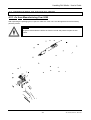
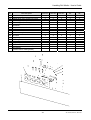
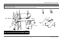
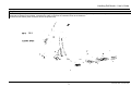
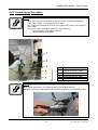
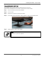
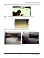
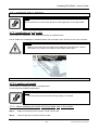
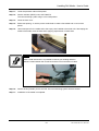
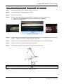
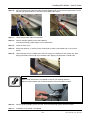
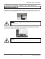
1
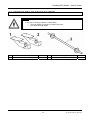
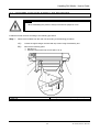
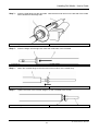
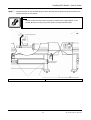
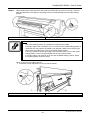
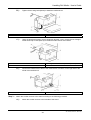
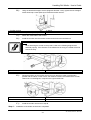
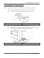
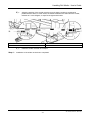
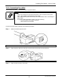
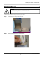
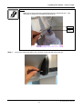
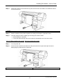
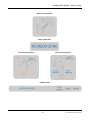
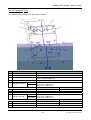
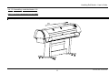
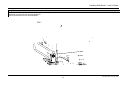
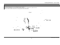
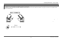
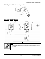
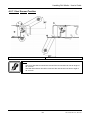
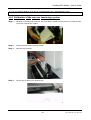
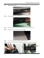
Handling roll media
Winder 30
Unwinder / Winder 100
User’s Guide
MUTOH EUROPE N.V.
AP-75100, Rev 2.0: , 26/11/2004
Handling Roll Media – User’s Guide
2
AP-75100, Rev.2.0, 26/11/04
Handling Roll Media – User’s Guide
COPYRIGHT NOTICE
COPYRIGHT © 2004 Mutoh Europe N.V. All rights reserved.
This document may not be reproduced by any means, in whole or in part, without written permission of the
copyright owner.
This document is furnished to support Mutoh’s roll-up / roll-off systems, waste bottle and how to handle roll
media on a Mutoh’s Rockhopper II series Printer. In consideration of the furnishing of the information
contained in this document, the party to whom it is given, assumes its custody and control and agrees to the
following:
The information herein contained is given in confidence, and any part thereof shall not be copied or
reproduced without written consent of Mutoh Europe N.V.
This document or the contents herein under no circumstances, shall be used in the manufacture or
reproduction of the article shown and the delivery of this document shall not constitute any right or license to
do so.
November 2004
Published: Mutoh Europe N.V., Archimedesstraat 13, B-8400 Oostende, BELGIUM
3
AP-75100, Rev.2.0, 26/11/04
Handling Roll Media – User’s Guide
4
AP-75100, Rev.2.0, 26/11/04
Handling Roll Media – User’s Guide
Dear Customer,
As standard, the Rockhopper II series printers come with a set of two scroller support brackets and a media
scroller (2” & 3” compatible). This system enables non-motorized unwinding of media rolls (2” / 3” core) up to
a weight of 30 kg.
For motorized unwinding and winding roll media, Mutoh has developed several options, enabling the user to
configure his machine “à la carte”, in accordance with his particular application needs.
The motorized unwinding and winding units are:
¾ winder 30
¾ unwinder / winder 100
As standard the Viper Digital Transfer Printer comes with the unwinder / winder 100.
In this manual you will find more information on how to install and use Mutoh’s roll-off / roll-up systems.
Depending on the system installed, the installation of the waste bottle will be different. Also this will be
explained in the manual.
For every roll-off / roll-up system is explained how to correctly handle roll media.
5
AP-75100, Rev.2.0, 26/11/04
Handling Roll Media – User’s Guide
6
AP-75100, Rev.2.0, 26/11/04
Handling Roll Media – User’s Guide
TABLE OF CONTENTS
1. Safety Instructions.........................................................................................................9
1.1. Introduction ............................................................................................................................ 9
1.2. Warnings, Cautions and Notes .............................................................................................. 9
1.3. Important safety instructions .................................................................................................. 9
2. Scroller receiver...........................................................................................................11
2.1. Warning labels ..................................................................................................................... 11
2.2. Verification of package items ............................................................................................... 12
2.3. Assembly of the scroller receiver ......................................................................................... 13
2.4. Installation of roll media onto the scroller receiver ............................................................... 15
2.5. Positioning the roll media ..................................................................................................... 18
3. Winder 30......................................................................................................................23
3.1. Verification of package items ............................................................................................... 23
3.1.1. Contents of packaged items (for 50” / 64”) ................................................................................... 23
3.1.2. Contents of packaged items (for 87”) ........................................................................................... 24
3.2. Assembling the winder 30 .................................................................................................... 25
3.2.1. Assembling the winder 30 (for 50” / 64”)....................................................................................... 25
3.2.2. Assembling the winder 30 (for 87”)............................................................................................... 28
3.2.3. Connecting the cables .................................................................................................................. 32
3.3. Waste bottle ......................................................................................................................... 33
3.4. Handling roll media on a winder 30...................................................................................... 36
3.4.1. Part names and functions ............................................................................................................. 36
3.4.2. Turning the power ON / OFF ........................................................................................................ 38
3.5. Loading roll media................................................................................................................ 39
3.5.1. Installation of roll media onto the scroller receiver ....................................................................... 39
3.5.2. Positioning roll media.................................................................................................................... 39
3.5.3. Attaching roll media to the winder 30............................................................................................ 39
4. Unwinder / winder 100 .................................................................................................43
4.1 Warning labels ...................................................................................................................... 43
4.2. Verification of package items ............................................................................................... 45
4.2.1. As from Manufacturing Year 2005 ................................................................................................ 45
4.2.2. Before Manufacturing Year 2005.................................................................................................. 48
4.3. Handling the unwinder / winder 100..................................................................................... 51
4.3.1. Part names and functions ............................................................................................................. 51
4.3.2. Turning the power ON / OFF ........................................................................................................ 53
4.4. Assembly ............................................................................................................................. 54
4.4.1. Assembling the unwinder / winder 100 and waste bottle.............................................................. 54
4.4.2 Connection of the cables. .............................................................................................................. 72
4.4.3. Positioning of the unit.................................................................................................................... 73
4.5. Sensor (tension bar) adjustment (before manufacturing year 2005).................................... 74
4.5.1. Understanding the principles of the sensors................................................................................. 74
4.5.2. Adjust the sensors of the front tensioning bar .............................................................................. 75
4.5.3. Adjust the sensors of the rear tensioning bar ............................................................................... 77
4.5.4. Sensor disc and adjustment direction........................................................................................... 80
4.5.5. Angle mark front tensioning system.............................................................................................. 81
4.5.6. Stop Sensor Position .................................................................................................................... 81
4.5.7. Start Sensor Position .................................................................................................................... 82
4.6 Calibration of the unwinder / winder 100............................................................................... 83
4.6.1 Calibration of the rear rear tensioning system ............................................................................... 83
4.6.2 Calibration of the front and rear roll unit. ....................................................................................... 86
4.7. Loading roll media................................................................................................................ 89
4.7.1. Installation of roll media ................................................................................................................ 89
4.7.2. Loading roll media......................................................................................................................... 89
4.8 Infrared dryer in combination with Mutoh’s Unwinder/Winder 100........................................ 94
7
AP-75100, Rev.2.0, 26/11/04
Handling Roll Media – User’s Guide
8
AP-75100, Rev.2.0, 26/11/04
Handling Roll Media – User’s Guide
1. SAFETY INSTRUCTIONS
1.1. INTRODUCTION
This chapter explains the meaning of safety terms for personnel who operate this equipment, important
safety instructions and the positions of the warning labels.
Important :
•
Be sure to follow all instructions and warnings in this manual when using the
equipment.
1.2. WARNINGS, CAUTIONS AND NOTES
Safety terms in this manual and the contents of warning labels attached to the printer are categorized into
the following three types depending on the degree of risk (or the scale of accident).
Read the following explanations carefully and follow the instructions in this manual.
Safety terms
Important
Caution
Notes
Details
Must be followed carefully to avoid death or serious bodily injury
Must be observed to avoid bodily injury (moderately or lightly) or damage to your
equipment
Contains important information and useful tips on the operation of your printer
Caution :
•
Read and understand the instructions mentioned in the unit’s User’s Guide.
1.3. IMPORTANT SAFETY INSTRUCTIONS
General safety instructions that must be observed to use the equipment safely are explained below.
¾
Do not stand on or place heavy objects on the unit. Doing so may result in the unit tipping or
falling over and causing injury.
¾
Do not attempt to plug in electrical plugs with wet hands. Doing so may result in electrical shock.
¾
Do not use thinner, benzene, alcohol or other active agents. Doing so may result in damage or
paint peeling from the casing.
¾
Be careful not to spill water inside the printer. Doing so may result in a short-circuit.
¾
Never open the covers fixed with screws. Doing so may result in electrical shock or a
malfunctioning in the unit.
¾
When setting roll media, place it on top of a desk or other flat surface. Setting roll media with the
scroller standing up may damage them.
9
AP-75100, Rev.2.0, 26/11/04
Handling Roll Media – User’s Guide
10
AP-75100, Rev.2.0, 26/11/04
Handling Roll Media – User’s Guide
2. SCROLLER RECEIVER
The Rockhopper II series printer is standard delivered with the scroller receiver.
2.1. WARNING LABELS
The handling, attachment locations and types of warning labels are explained below.
Warning labels are attached on areas which require attention. Read and understand the positions and
contents thoroughly before performing your work.
Be sure to note the following when handling the labels.
Notes :
•
•
•
Make sure that all labels can be recognized. If text or illustrations cannot be seen
clearly, either clean or replace the label.
When cleaning labels, use a cloth with water or neutral detergent. Do not use a
solvent or gasoline.
If a warning label is damaged, lost, or cannot be recognized, replace the label.
When replacing warning labels, contact your local MUTOH dealer.
CAUTION
VORSICHT
ATTENTION
> In order to be able to unroll the media, do not slant or stand the media scroller.
> When setting roll media, place the scroller on top of a desk or other flat surface. Setting roll
media with the scroller standing up may damage both scroller and roll media.
> Bitte setzen Sie die Rollenhalterung nicht abschüssig oder aufrecht, sonst wird die Rollenmedia
sich nicht entrollen.
> Wenn Sie Rollenmedia installieren, plazieren Sie die Mediarolle auf einem Schreibtisch oder
einem anderen Platz. Wenn Sie Rollenmedia installieren mit der Mediarolle vertikal, können Sie
sowohl die Mediarolle als auch die Rollenmedia beschädigen.
> Ne mettez pas l'axe-rouleau en position verticale ou inclinée, sinon le support en rouleau ne se
déroulera pas.
> Si vous chargez le support en rouleau, mettez l'axe-rouleau sur un bureau ou une autre surface.
Si vous chargez le support en rouleau avec l'axe-rouleau en haut, vous pouvez endommager
aussi bien l'axe-rouleau que le support en rouleau.
11
AP-75100, Rev.2.0, 26/11/04
Handling Roll Media – User’s Guide
2.2. VERIFICATION OF PACKAGE ITEMS
Caution :
•
1
3
If any part is- missing or broken, contact either
o The shop where you bought your MUTOH printer.
o Your local MUTOH dealer.
Scroller receiver (left side)
Scroller
1
1
2
12
Scroller receiver (right side)
1
AP-75100, Rev.2.0, 26/11/04
Handling Roll Media – User’s Guide
2.3. ASSEMBLY OF THE SCROLLER RECEIVER
Caution :
•
When assembling this product, always work with two people or more.
Install the scroller receiver according to the following procedure.
Step 1 :
Remove the handles from the main unit according to the following procedure.
A):
Loosen the eight hexagon socket head cap screws using the assembly tool.
B):
Remove the following parts:
¾ Handles (2)
¾ Hexagon socket head cap screws (M6 x 16: 8)
1. Handle
3. Main unit
2. Hexagon socket head cap screw (M6 x 16)
13
AP-75100, Rev.2.0, 26/11/04
Handling Roll Media – User’s Guide
2.4. INSTALLATION OF ROLL MEDIA ONTO THE SCROLLER
RECEIVER
The procedure for installation of roll media onto the scroller receiver is explained below.
Notes :
•
You can attach roll media with a 2 inch (outer diameter: 103 mm or smaller; weight
maximum 30 kg) or 3 inch media tube (outer diameter: 150 mm or smaller; weight
maximum 30 kg) to your printer. Please note that for the 87” model only a 3”
scroller is available.
To attach roll media, follow the steps below.
Caution :
•
•
•
Step 1 :
When setting roll media, place it on top of a desk or other flat surface.
Position the roll media in such way that finally, the printing side will be “upside” in
the printer.
Setting roll media with the scroller standing up may damage them.
Slide and remove the movable flange from the scroller.
1. Scroller
Step 2 :
2. Movable flange
When using roll media with a media tube diameter of 2 inches, remove the movable flange and
the fixed flange adapter.
1. Movable flange
3. Adapter
2. Fixed flange
15
AP-75100, Rev.2.0, 26/11/04
Handling Roll Media – User’s Guide
Step 3 :
Insert the fixed flange into the roll media. Note that the media end is on the left side of the media
when viewed from the flange side.
1. Fixed flange
Step 4 :
2. Roll media
Insert the flange until the right end meets the media tube of the roll media.
1. Fixed flange
Step 5 :
2. Roll media
Attach the movable flange to the other end of the media to fix the media firmly.
1. Movable flange
Step 6 :
2. Roll media
Tighten the screw of the movable flange to fix the roll media to the scroller.
1. Movable flange
2. Scroller
16
AP-75100, Rev.2.0, 26/11/04
Handling Roll Media – User’s Guide
Step 7 :
Hold the scroller so that the fixed flange is at the left side and set both ends of the scroller to the
scroller receivers on the printer.
Notes :
•
Set the scroller onto the printer correctly by referring to the figure below. If the
scroller direction is wrong, the printer cannot correctly feed the media.
1. Scroller receiver
2. Scroller
17
AP-75100, Rev.2.0, 26/11/04
Handling Roll Media – User’s Guide
2.5. POSITIONING THE ROLL MEDIA
The procedure for positioning roll media is explained below.
To position roll media, follow the steps below.
Step 1 :
Turn the printer ON.
Step 2 :
The printer starts the initializing operation.
¾ The following message is displayed on the operation panel.
→ Paper End
Heaters
Cleaning
18
AP-75100, Rev.2.0, 26/11/04
Handling Roll Media – User’s Guide
Step 5 :
Open the front cover.
Caution :
•
Be careful not to pinch your fingers when opening and closing the front cover.
1. Front cover
Step 6 :
Load the roll media into the insertion slot at the back of the printer.
Notes :
•
If there is a p4.3994 579 9ightly wyounide51(dat9)]TJ98.1986 0 TD[( theendk of thee)6 roll medla
19
AP-75100, Rev.2.0, 26/11/04
Handling Roll Media – User’s Guide
Step 8 :
While holding down the end of the media, hold the scroller and roll out a bit of media. Remove
slack and skewness, then align the right edge of the roll media parallel with the media loading
position.
1. Scroller
2. Media loading position
Notes :
•
•
•
•
The media loading position is a guideline for setting up the media.
If the right edge of the roll media is 5 mm or more from the media setting position, a
media set error may result if the media is not detected. Make sure to set the right
edge of the roll media within 5 mm of the media setting position.
If it is not possible to set the right edge of the roll media within 5 mm of the media
setting position, refer to the figure below and set the scroller position.
If the right edge of roll media is not in line with the Media loading position, adjust
the scroller position as shown below.
When moving the roll media to the left
¾ Rotate the scroller adjustment screw counterclockwisely.
1. Scroller adjustment screw
3. Roll media
2. Scroller
4. Media loading position
20
AP-75100, Rev.2.0, 26/11/04
Handling Roll Media – User’s Guide
When moving the roll media to the right
¾ Rotate the scroller adjustment screw clockwisely.
1. Scroller adjustment screw
3. Roll media
Step 9 :
2. Scroller
4. Media loading position
Press the [F4] key on the operation panel to lower the pressure rollers.
¾ The MEDIA SET lamp will turn off.
Step 10 : Close the front cover.
Caution :
•
Be careful not to pinch your fingers when opening and closing the front cover.
Notes :
•
If you load a new media roll, the media end may not be straight. If so, cut the end
of the roll media.
1. Front cover
Step 11 : The media initial menu is displayed on the operation panel.
* PaperInitialMenu *
F3 → LeverUp
F2, F4 → ENTER or F3
21
Roll ← F2
User1 ← F4
AP-75100, Rev.2.0, 26/11/04
Handling Roll Media – User’s Guide
22
AP-75100, Rev.2.0, 26/11/04
Handling Roll Media – User’s Guide
3. WINDER 30
3.1. VERIFICATION OF PACKAGE ITEMS
After unpacking the packaging box, inspect to make sure if the unit is not damaged and that all necessary
23
AP-75100, Rev.2.0, 26/11/04
Handling Roll Media – User’s Guide
3.1.2. Contents of
24
itemnts
AP-75100, Rev.2.0, 26/11/04
Handling Roll Media – User’s Guide
3.2. ASSEMBLING THE WINDER 30
The assembly of this product is described below.
Caution :
•
When assembling this product, always work with two people or more.
Refer to the following items according to the model to be used before assemble the product.
• For 50” / 64”
• Refer to ‘Assembling the winder 30 (for 50” / 64”)’ and ‘Connecting the power cable’
• For 87”
• Refer to ‘Assembling the winder 30 (for 87”)’ and ‘Connecting the power cable’
3.2.1. Assembling the winder 30 (for 50” / 64”)
Assemble the product according to the following procedure.
Step 1 :
Install the winder 30 to the stand according to the following procedure.
A):
Attach the winder 30 motorized unit to the right side of the stand.
B):
Using the attached hexagon wrench (diagonal diameter 5 mm), tighten the four hexagon
socket head cap screws (M6x60) to install the winder 30 motorized unit.
1. Winder 30 motorized unit
2. Stand
Step 2 :
3. Hexagon socket head cap screws (M6x60)
Install the media sensor to the stand.
A):
Attach the media sensor and the two wing bolts (M3x8) under the bottom of the winder
30 motorized unit.
25
AP-75100, Rev.2.0, 26/11/04
Handling Roll Media – User’s Guide
B):
Tighten the two wing bolts (M3x8) to install the media sensor.
1. Media sensor
2. Winder 30 motorized unit
C):
3. Wing bolt (M3x8)
Using the attached hexagon wrench (diagonal diameter 3 mm), tighten the two hexagon
socket head cap screws (M4x10) to install the media sensor to the stand.
1. Media sensor
2. Stand
D):
3. Hexagon socket head cap screw (M4x10)
Connect the media sensor cable to the media sensor connector on the right side of the
winder 30 motorized unit.
1. Media sensor cable
Step 3 :
2. Media sensor connector
Attach the scroller receiver to the stand according to the following procedure.
A):
Attach the scroller receiver to the left side of the stand.
26
AP-75100, Rev.2.0, 26/11/04
Handling Roll Media – User’s Guide
B):
Using the attached hexagon wrench (diagonal diameter 3 mm), tighten the two hexagon
socket head cap screws (M4x10) to install the scroller receiver.
1. Scroller receiver
3. Hexagon socket head cap screw (M4x10)
2. Stand
C):
Attach the media tube to the scroller.
D):
Install the scroller onto the scroller receiver and winder 30 motorized unit.
Notes :
•
When attaching the scroller to the product, refer to the following diagram and
attached properly. If the direction of the attachment is wrong, the media will not be
wound correctly.
1. Scroller
3. Scroller receiver
E):
2. Winder 30 motorized unit
Adjust the position of the scroller receiver as such that the scroller is positioned in
parallel with the stand; in other words, the distance between the stand and the scroller,
referred as L in the diagram, is equal on the right and left side.
1. Scroller
3. Scroller receiver
F):
Step 4 :
2. Stand
Install the scroller receiver as in step B.
Installation of the winder 30 has been completed.
27
AP-75100, Rev.2.0, 26/11/04
Handling Roll Media – User’s Guide
3.2.2. Assembling the winder 30 (for 87”)
Assemble the product according to the following procedure.
Step 1 :
Install the winder 30 motorized unit to the stand according to the following procedure.
A):
Attach the winder 30 bracket to the left side of the winder 30 motorized unit.
B):
Tighten the four flat head screws (M4x5) to install the winder 30 bracket.
1. Winder 30 bracket
2. Winder 30 motorized unit
3. Flat head screws (M4x5)
C):
Attach the winder 30 bracket to the right side of the stand.
D):
Using the attached hexagon wrench (diagonal diameter 3 mm); tighten the four hexagon
socket head cap screws (M4x10) to install the winder 30 bracket.
1. Winder 30 bracket
3. Hexagon socket head cap screw (M4x10)
2. Stand
28
AP-75100, Rev.2.0, 26/11/04
Handling Roll Media – User’s Guide
Step 2 :
Install the media sensor to the stand.
A):
Attach the media sensor and the two wing bolts (M3x8) at the bottom of the winder 30
motorized unit.
B):
Tighten the two wing bolts (M3x8) to install the media sensor.
1. Media sensor
3. Wing bolt (M3x8)
C):
2. Winder 30 motorized unit
Using the attached hexagon wrench (diagonal diameter 3 mm), tighten the two hexagon
socket head cap screws (M4x10) to install the media sensor on the stand.
1. Media sensor
3. Hexagon socket head cap screw (M4x10)
D):
2. Stand
Connect the media sensor cable to the media sensor connector at the right side of the
roll-up system.
1. Media sensor cable
2. Media sensor connector
29
AP-75100, Rev.2.0, 26/11/04
Handling Roll Media – User’s Guide
Step 3 :
Attach the scroller receiver to the stand according to the following procedure.
A):
Attach the scroller receiver to the left side of the stand.
B):
Using the attached hexagon wrench (diagonal diameter 3 mm), tighten the two hexagon
socket head cap screws (M4x10) to install the scroller receiver.
1. Scroller receiver
3. Hexagon socket head cap screw (M4x10)
2. Stand
C):
Attach the media tube to the scroller.
D):
Attach the scroller both to the winder 30 motorized unit and the scroller receiver.
Notes :
•
When attaching the scroller to the product, refer to the following diagram and attach
properly. If the direction of the attachment is wrong, the media will not be wound
correctly.
1. Scroller
3. Scroller receiver
2. Winder 30 motorized unit
30
AP-75100, Rev.2.0, 26/11/04
Handling Roll Media – User’s Guide
E):
Adjust the position of the scroller receiver as such that the scroller is positioned in
parallel with the stand; in other words, the distance between the stand and the scroller,
referred as L in the diagram, is equal at the right and left side.
1. Scroller
3. Scroller receiver
F):
Step 4 :
2. Stand
Install the scroller receiver as in step B.
Installation of the winder 30 has been completed.
31
AP-75100, Rev.2.0, 26/11/04
Handling Roll Media – User’s Guide
3.2.3. Connecting the cables
The connection procedure for the power cable is explained below.
Notes :
•
•
•
Refer to the following for important information on the connection of the power
cable. User’s Guide : Connecting the power cable.
Use a cable that is suitable to the local power specifications when connecting the
power cable.
If the power cable is damaged, contact one of the following :
o The shop where you bought the product
o Nearest MUTOH local dealer
Connect the power cable according to the following procedure.
Step 1 :
Make sure that the printer is OFF.
1. Power switch
Step 2 :
Plug the power cable to the AC inlet on the left side of the winder 30 motorized unit.
1. AC inlet
Step 3 :
2. Power cable
Plug the cable correctly to the outlet.
32
AP-75100, Rev.2.0, 26/11/04
Handling Roll Media – User’s Guide
3.3. WASTE BOTTLE
Caution :
•
Before powering ON the unit, install the waste bottle.
Install the waste fluid tank according to the following procedure.
Step 1 :
Install the tank tray to the right side of the stand.
Step 2 :
Connect the waste fluid tube to the waste fluid tank.
33
AP-75100, Rev.2.0, 26/11/04
Handling Roll Media – User’s Guide
Notes :
•
Make sure to firmly connect the waste fluid tube to the waste fluid tank. If the
connection is insufficient, the waste fluid will leak out.
1 cm
2 cm
Step 3 :
Connect the waste tank cable to the connector on the rear side of the main unit.
34
AP-75100, Rev.2.0, 26/11/04
Handling Roll Media – User’s Guide
Step 4 :
Mount a cable clamp and two tube clamps on the stand to fix the waste tank cable and waste
tank tubes.
Step 5 :
Make sure that the waste will go down in one fluent way.
Step 6 :
Installing the waste fluid tank is completed.
35
AP-75100, Rev.2.0, 26/11/04
Handling Roll Media – User’s Guide
3.4. HANDLING ROLL MEDIA ON A WINDER 30
This chapter explains how to handle the product.
3.4.1. Part names and functions
Part names and functions are explained below.
3.4.1.1. Winder 30
No.
1
2
3
4
5
Name
Winder 30 motorized unit
Media sensor
Scroller receiver
Power switch
Operation Panel
Function
Winds and collects the printed roll media.
Detects the printed media.
Loads the scroller for the winding unit.
Turn the product ON and OFF.
This panel is used to set operational conditions, and the status of
the product.
36
AP-75100, Rev.2.0, 26/11/04
Handling Roll Media – User’s Guide
3.4.1.2. Operation Panel
The operation panel is used to set operational conditions and to check / display the status of the product.
(1) Operation switches
No.
1
Name
AUTO switch
2
MANUAL switch
Function
Used to automatically wind the roll media.
→ Forward : When the media sensor detects the media, the
scroller automatically rotates forward. The media is wound with
the printed side at the outside.
→ OFF : Used when operating the MANUAL switch.
→ Backward : When the media sensor detects the media, the
scroller automatically rotates backward. The media is wound with
the printed side at the inside.
The winder system is manually operated.
→ Forward : The scroller rotates forward.
→ Backward : The scroller rotates backward.
(2) Status Lamp
No.
3
Name
SENSOR lamp
Status
ON
Flashing
OFF
Function
The product is ON.
Waiting
An error has occurred.
The product is winding the media.
The product is OFF.
37
AP-75100, Rev.2.0, 26/11/04
Handling Roll Media – User’s Guide
3.4.2. Turning the power ON / OFF
The methods to turn the power ON or OFF are described below.
2.4.2.1. Turning the power ON
Turn the power of the unit ON according to the following procedure.
Step 1 :
Turn the power switch ON.
¾ The product turns the power ON.
¾ The SENSOR lamp will light.
1. Power switch
3.4.2.2. Turning the power OFF
Turn the power OFF according to the following procedure.
Step 1 :
Make sure the product is not winding.
Step 2 :
Turn the power switch OFF.
¾ The product turns the power OFF.
¾ The SENSOR lamp will turn off.
1. power switch
38
AP-75100, Rev.2.0, 26/11/04
Handling Roll Media – User’s Guide
3.5. LOADING ROLL MEDIA
3.5.1. Installation of roll media onto the scroller receiver
To install roll media onto the scroller receiver, please refer to the chapter Scroller Receiver”.
3.5.2. Positioning roll media
To position the roll media, please refer to the chapter “Scroller Receiver”.
3.5.3. Attaching roll media to the winder 30
The procedure for attaching roll media to the winder 30 is explained below.
To attach roll media, follow the steps below.
3.5.3.1. When winding the media with the printed side outside.
Step 1 :
Turn the power ON.
Step 2 :
Pull out the roll media from the feed slot of the printer and fix into place with tape so that the
leading edge is parallel with the media tube.
1. Roll media
2. Media tube
39
AP-75100, Rev.2.0, 26/11/04
Handling Roll Media – User’s Guide
Step 3 :
Rotate the scroller to forward direction by hand, and wind the roll media on the media tube about
one and a half turns.
1. scroller
Step 4 :
Set the conditions of the product operation according to the steps in “Operation Panel”.
Step 5 :
Load the media and set the media type according to the User’s Guide.
¾ Media loading is completed.
¾ The printer starts printing and the roll media is automatically wound onto the scroller.
3.5.3.2. When winding the media with the printed side inside.
Step 1 :
Turn the power ON.
Step 2 :
Pull out the roll media from the feed slot of the printer and fix into place with tape so that the
leading edge is parallel with the media tube.
1. Roll media
2. Media tube
40
AP-75100, Rev.2.0, 26/11/04
Handling Roll Media – User’s Guide
Step 3 :
Rotate the scroller to forward direction by hand, and wind the roll media onto the media tube
about one and a half turns.
1. scroller
Step 4 :
Set the conditions of the product operation according to the steps in “Operation Panel”.
Step 5 :
Load the media and set the media type according to the User’s Guide.
¾ Media loading is completed.
¾ The printer starts printing and the roll media is automatically wound onto the scroller.
41
AP-75100, Rev.2.0, 26/11/04
Handling Roll Media – User’s Guide
42
AP-75100, Rev.2.0, 26/11/04
Handling Roll Media – User’s Guide
4. UNWINDER / WINDER 100
This chapter is divided in two. This because there has to be made a difference between unwinder/winder 100
systems manufactured before 2005 and system manufactured as from 2005.
As from manufacturing date 2005
43
AP-75100, Rev.2.0, 26/11/04
Handling Roll Media – User’s Guide
Roll unit handle label
Paper guide label
Front tensioning label
Rear tensioning label
PCB box label
44
AP-75100, Rev.2.0, 26/11/04
Handling Roll Media – User’s Guide
4.2. VERIFICATION OF PACKAGE ITEMS
4.2.1. As from Manufacturing Year 2005
After unpacking the packaging box, inspect to make sure if the unit is not damaged and that all necessary
parts are present.
Caution :
The parts not described are buffers as function to hold and protect the parts in their
position.
45
AP-75100, Rev.2.0, 26/11/04
Handling Roll Media – User’s Guide
Nr.
5
11
12
14
15
21
22
23
24
25
26
27
29
30
31
34
35
37
Part Description
2
2
2
1
1
DT-series
65”
2
2
2
1
1
DT-series
90”
2
2
2
1
1
/
4
/
4
1
2
1
1
1
2
1
1
1
2
1
1
1
2
1
1
1
2
1
1
4
4
4
4
4
1
1
1
2
1
2
1
1
1
2
1
2
1
1
1
2
1
2
1
1
1
2
1
2
1
1
1
2
1
2
1
1
1
1
1
RHII 50”
RHII 64”
RHII 87”
2
2
2
1
1
2
2
2
1
1
/
Steel Bar Assy
Sledge Left Assy Rollfeed Universal
Sledge Right Assy Rollfeed Universal
Tensioning bar Assy Rollfeed
Tensioning bar Front Assy Rollfeed
Adjusting Foot Bracket Roll feed
Universal
Fix plate RF Waste Bottle
Bump Plate Rollfeed
Foot switch KF2 – 1S/1S
PCB Box Assy Rollfeed
Sledge Lock Bracket Part 2 Rollfeed
universal
Leg Clamp Part 1 Rollfeed
Mounting Bracket Left Assy Rollfeed
Mounting Bracket Right Assy Rollfeed
Leg Clamp Part 2 Rollfeed
Waste Ink Tank Bracket Assy Rollfeed
Cardboard Core 3 inch
Kit Rollfeed
(please refer to drawing below)
46
AP-75100, Rev.2.0, 26/11/04
Handling Roll Media – User’s Guide
Nr.
1
2
3
4
5
6
7
8
9
10
11
12
13
14
15
16
17
18
20
21
Part Description
RHII 50”
RHII 64”
RHII 87”
4
8
5
8
8
8
4
4
4
1
1
1
1
10
4
8
1
1
2
1
4
8
5
8
8
8
4
4
4
1
1
1
1
10
4
8
1
1
2
1
4
8
5
8
24
8
4
4
4
1
1
1
1
10
4
8
1
1
6
1
Shaft Tensioning bar D-lock Rollfeed
DIN 912 Standard M6x12 ELVZ
Lock Washer Internal Teeth M6 ELVZ
Spacer PA D18xd8.2xH10
Hex Flange Button head M5x8 ELVZ
DIN912 Standard M6x16 ELVZ
DIN 912 Standard M6x55 ELVZ
Pan Head Screw M4x10
DIN 7985 M3x5 ELVZ
Hexagon Key DIN911 #2.5
Hexagon Key DIN911 #3
Hexagon Ball Key DIN911 #4
Hexagon Key DIN911 #5 long
Adjusting Spacer Rollfeed Universal
Clamp Lever M10 x 40
Plain Washer DIN125-1 A M6
Adjustment Tooling Rollfeed
PET Adjusting Strip Rollfeed
Leveling elements M12
Keyboard Cable Rollfeed
DT-series
65”
4
8
5
8
8
8
4
4
4
1
1
1
1
10
4
8
1
1
2
1
DT-series
90”
4
8
5
8
24
8
4
4
4
1
1
1
1
10
4
8
1
1
6
1
Caution :
•
If any part is- missing or broken, contact either
o The shop where you bought your MUTOH printer.
o Your local MUTOH dealer.
47
AP-75100, Rev.2.0, 26/11/04
Handling Roll Media – User’s Guide
4.2.2. Before Manufacturing Year 2005
After unpacking the packaging box, inspect to make sure if the unit is not damaged and that all necessary
parts are present.
Caution :
The parts not described are buffers as function to hold and protect the parts in their
position.
48
AP-75100, Rev.2.0, 26/11/04
Handling Roll Media – User’s Guide
Nr.
5
11
13
14
15
21
22
23
24
25
26
28
29
30
31
32
35
36
37
Part Description
2
2
2
1
1
DT-series
65”
2
2
2
1
1
DT-series
90”
2
2
2
1
1
/
4
/
4
1
2
1
1
1
2
1
1
1
2
1
1
1
2
1
1
1
2
1
1
4
4
4
4
4
1
1
1
1
2
1
2
1
1
1
1
2
1
2
1
1
1
1
2
1
2
1
1
1
1
2
1
2
1
1
1
1
2
1
2
1
1
1
1
1
RHII 50”
RHII 64”
RHII 87”
2
2
2
1
1
2
2
2
1
1
/
Steel Bar Assy
Sledge Left Assy Rollfeed Universal
Sledge Right Assy Rollfeed Universal
Tensioning bar Assy Rollfeed
Tensioning bar Front Assy Rollfeed
Adjusting Foot Bracket Roll feed
Universal
Fix plate RF Waste Bottle
Bump Plate Rollfeed
Foot switch KF2 – 1S/1S
PCB Box Assy Rollfeed
Sledge Lock Bracket Part 2 Rollfeed
universal
Mounting Bracket Right Assy Rollfeed
Mounting Bracket Left Assy Rollfeed
Keyboard Assy Rollfeed Universal
Leg Clamp Part 2 Rollfeed
Leg Clamp Part 1 Rollfeed
Waste Ink Tank Bracket Assy Rollfeed
Cardboard Core 3 inch
Kit Rollfeed
(please refer to drawing below)
49
AP-75100, Rev.2.0, 26/11/04
Handling Roll Media – User’s Guide
Nr.
1
2
3
4
5
6
7
8
9
10
11
12
13
14
15
16
17
18
19
20
21
22
23
24
Part Description
Sensor Lip Assy Rollfeed
Shaft Tensioning bar Rollfeed
DIN 912 Standard M6x12 ELVZ
Lock Washer Internal Teeth M6 ELVZ
Lock Washer External Teeth M5 ELVZ
Spacer PA D18xd8.2xH10
Hex Flange Button head M5x8 ELVZ
DIN 912 Standard M6x16 ELVZ
DIN 912 Standard M6x55 ELVZ
Pan Head Screw M4x10
DIN 7985 M3x5 ELVZ
Hexagon Key DIN911 #2.5
Hexagon Key DIN911 #3
Hexagon Ball Key DIN911 #4
Hexagon Key DIN911 #5 long
Hexagon Key DIN911 #1,5
Adjusting Spacer Rollfeed Universal
Clamp Lever M10 x 40
Plain Washer DIN125-1 A M6
Adjustment Tooling Rollfeed
PET Adjusting Strip Rollfeed
DVD assy Instructions Rollfeed RH2
Leveling elements M12
Keyboard Cable Rollfeed
RHII 50”
2
2
8
1
4
4
10
8
4
4
4
1
1
1
1
1
5
2
8
1
1
1
1
1
RHII 64”
2
2
8
1
4
4
10
8
4
4
4
1
1
1
1
1
5
2
8
1
1
1
1
1
RHII 87”
2
2
8
1
4
4
18
8
44
6
4
1
1
1
1
1
5
2
8
1
1
1
3
1
Caution :
•
If any part is- missing or broken, contact either
o The shop where you bought your MUTOH printer.
o Your local MUTOH dealer.
50
AP-75100, Rev.2.0, 26/11/04
Handling Roll Media – User’s Guide
4.3. HANDLING THE UNWINDER / WINDER 100
This chapter explains how to handle the product.
4.3.1. Part names and functions
Part names and functions are explained below.
4.3.1.1. Unwinder / winder 100
No.
1
Name
Roll-Off System
2
Rear Tension system
Function
This is the device that sets the media when using roll media and
feeds it to the printing position.
Adjust the tension of the media between the roll-off system and
the media feed slot.
51
AP-75100, Rev.2.0, 26/11/04
Handling Roll Media – User’s Guide
4.3.1.2. Operation Panel
The operation panel is used to set operational conditions.
No.
A
B
Name
/
/
1
Print Side Selector
2
Unwinder 100 power ON
Manual
Unwinder 100 LED
Automatic
3
4
5
6
7
8
9
10
Backwards button
Forwards button
Winder 100 power ON
Manual
Winder 100 LED
Automatic
Backwards button
Forwards button
Power LED
Function
Part of the operation panel controlling the unwinder 100.
Part of the operation panel controlling the winder 100.
In case you loaded media with printed side on the outside select
‘OUT’, otherwise select ‘IN’.
Toggle between Manual and Automatic mode.
LED lights up when pushing one of the buttons
Motor turns: LED flashes.
Motor is off : LED is out.
Outside printing
Inside printing
Roll-off unwinder
Roll-up unwinder
Roll-up unwinder
Roll-off unwinder
Power ON or OFF the winder 100.
LED lights up when pushing one of the buttons
Motor turns: LED flashes
Motor is off : LED is out.
Outside printing
Inside printing
Roll-off winder
Roll-off winder
Roll-up winder
Roll-up winder
Lightens up the system is powered ON.
52
AP-75100, Rev.2.0, 26/11/04
Handling Roll Media – User’s Guide
4.3.2. Turning the power ON / OFF
The methods to turn the power ON or OFF are described below.
4.3.2.1. Turning the power ON
Turn the power of the unit ON according to the following procedure.
Step 1 :
Turn the power switch ON.
¾ The product turns the power ON.
¾ The power lamp on the operation panel will light.
1. Power switch
When using the unwinder / winder 100, please make sure to select the option “Rollfeed”.
* Detection *
F1 → Normal
F3 → TakeupRoll
Current parameter → - Rollfeed Setup items
media detect
Off ← F2
RollFeed ← F4
(1/1)
Parameters
RollFeed
Description
Make this setting when using the optional winder /
unwinder 100
4.3.2. Turning the power OFF
Turn the power OFF according to the following procedure.
Step 1 :
Make sure the product is not winding.
Step 2 :
Turn the power switch OFF.
¾ The product turns the power OFF.
¾ The power lamp on the operation panel will turn off.
1. power switch
53
AP-75100, Rev.2.0, 26/11/04
Handling Roll Media – User’s Guide
4.4. ASSEMBLY
The assembly of the unwinder / winder 100 is divided into two parts.
¾ Assembling the motorized roll-off/roll-up system
¾ Assembling the tensioning system
4.4.1. Assembling the unwinder / winder 100 and waste bottle
To assemble the unwinder / winder 100 and waste bottle onto the Rockhopper II series printer, please follow
the instructions mentioned onto the CD-rom included with this manual.
Caution :
•
•
•
Please note it is necessary to remove the scroller receiver before installation of the
unwinder / winder 100.
Please note that all parts described in the drawings, can slightly be different on the
drawing then in-the-box. This because of revisions.
Make sure the printer is positioned stable and horizontally (before installation of the
unwinder/winder 100). Make use of a level.
This chapter is divided in two. This because there has to be made a difference between unwinder/winder 100
systems manufactured before 2005 and system manufactured as from 2005.
As from manufacturing date 2005
Before manufacturing date 2005
54
AP-75100, Rev.2.0, 26/11/04
Handling Roll Media – User’s Guide
4.4.1.2 Assembling unwinder/winder 100
4.4.1.2.1 As from manufacturing year 2005
If necessary, remove all parts of the current winder system.
55
AP-75100, Rev. 2.0, 26/11/04
Handling Roll Media – User’s Guide
Step 1 :
Assemble the Foot Mounting Brackets with 8 bolts M6x12. Make sure the Waste-ink Tank Bracket is on the right hand side of the machine.
56
AP-75100, Rev. 2.0, 26/11/04
Handling Roll Media – User’s Guide
Step 2 :
Assemble the PCB-box, using 4 bolts M6x55 and 4 teeth washers M6..
57
AP-75100, Rev. 2.0, 26/11/04
Handling Roll Media – User’s Guide
Step 3 :
On the 87” printer, assemble the support brackets and adjusting feet on both ends of the rail.
Assemble the adjusting foot on the middle bracket of the rail.
Place the rail assembly on the leg clamps. Use the hole/slot hole combinations to position the rail.
Make sure the short side of the rail is on the right-hand side of the printer.
58
AP-75100, Rev. 2.0, 26/11/04
Handling Roll Media – User’s Guide
Step 4 :
Assemble the Roll support Assemblies.
Make sure to driven roll support (with motor and cable) is on the right hand side of the machine.
Connect the motor cable to the PCB-box (Front motor: connector next to the power inlet, Rear motor: second connector next to the power inlet)
59
AP-75100, Rev. 2.0, 26/11/04
Handling Roll Media – User’s Guide
Step 5 :
Assemble the left and right mounting brackets. Use 4 bolts M6x16 with a plain washer M6 on each bracket. Use 1 teeth washer M6 on the right bracket.
Do not tighten the bolts on the left bracket yet.
Only the 87” printer, use the most outer holes on the left side of the printer for assembling the left mounting bracket.
60
AP-75100, Rev. 2.0, 26/11/04
Handling Roll Media – User’s Guide
Step 6 :
Assemble the 2 shafts in the left Mounting bracket assembly.
Assemble the front and rear swingbar assembly.
Use the screws M4x10 to fix the assemblies
61
AP-75100, Rev. 2.0, 26/11/04
Handling Roll Media – User’s Guide
Step 7 :
After alignment (and putting the spacer in place – if necessary) of the front and rear rolldrive assemblies, use the bolts M5x8 and white spacers to fix the rolldrive
assemblies.
62
AP-75100, Rev. 2.0, 26/11/04
Handling Roll Media – User’s Guide
4.4.1.2.2 Before manufacturing year 2005
If necessary, remove all parts of the current winder system.
63
AP-75100, Rev. 2.0, 26/11/04
Handling Roll Media – User’s Guide
Step 1 :
Assemble the Foot Mounting Brackets with 8 bolts M6x12. Make sure the Waste-ink Tank Bracket is on the right hand side of the machine.
64
AP-75100, Rev. 2.0, 26/11/04
Handling Roll Media – User’s Guide
Step 2 :
Assemble the PCB-box, using 4 bolts M6x55 and 4 teeth washers M6..
65
AP-75100, Rev. 2.0, 26/11/04
Handling Roll Media – User’s Guide
Step 3 :
On the 87” printer, assemble the support brackets and adjusting feet on both ends of the rail.
Assemble the adjusting foot on the middle bracket of the rail.
Place the rail assembly on the leg clamps. Use the hole/slot hole combinations to position the rail.
Make sure the short side of the rail is on the right-hand side of the printer.
66
AP-75100, Rev. 2.0, 26/11/04
Handling Roll Media – User’s Guide
Step 6 :
Remove the rear cover on the right mounting bracket. Remove the 3 screws holding the operation panel. Put the operating panel aside.
BE CAREFUL NOT TO DAMAGE THE CABLES LEADING TO THE PANEL.
Assemble the 4 shafts. On the right hand side, assemble 2 detection lips on each shaft, each detection should be in the gap of the sensors. Do not tighten the set
screws on the sensor lips.
69
AP-75100, Rev. 2.0, 26/11/04
Handling Roll Media – User’s Guide
Step 7 :
Assemble the rear tensioning system, using 2 screws M4x10. Put a lock washer M5 between each screw and tensioning system shaft.
TIGHTEN THE SCREWS FIRMLY
After assembling the front and rear tensioning system, tighten the bolts on the left support bracket.
ITEM
1
2
3
4
PART DESCRIPTION
Lock Washer External Teeth M5 ELVZ
Pan Head Screw M4x10
Rear tensioning system assy Rollfeed Rockhopper II 87”
Front tensioning system assy Rollfeed Rockhopper II 87”
QUANTITY
4
4
1
1
70
AP-75100, Rev. 2.0, 26/11/04
Handling Roll Media – User’s Guide
Step 8 :
Perform the alignment procedure. After inserting the adjusting spacers (if necessary), fix the Rail assembly with 2 spacers and 2 cap screws on each side.
Assemble the waste-ink tank holder. Assemble the cable connecting the operating panel to the PCB-box.
Connect the foot switch (third connector next to the power inlet)
71
AP-75100, Rev. 2.0, 26/11/04
Handling Roll Media – User’s Guide
4.4.2 Connection of the cables.
Notes :
•
•
•
Refer to the following for important information on the connection of the power
cable. User’s Guide : Connecting the power cable.
Use a cable that is suitable to the local power specifications when connecting the
power cable.
If the power cable is damaged, contact one of the following :
o The shop where you bought the product
o Nearest MUTOH local dealer
Nr.
1
2
3
4
5
Description
Flat cable connected to control
panel of the winder system
Footswitch cable
Rear motorized unit cable
Front motorized unit cable
Power supply cable.
Notes :
With a small intervention it is possible to reverse your winding direction.
Mount the conversion cable between the control box and the front motorized unit cable.
72
AP-75100, Rev. 2.0, 26/11/04
Handling Roll Media – User’s Guide
4.4.3. Positioning of the unit
After installation of the unwinder / winder 100, please make sure to lock the unit.
Please choose an adequate place for your printer. (Please refer to the User’s Guide)
Step 1 :
First move the printer to where it will be installed.
Step 2 :
Lock the casters.
Step 3 :
Rotate the four adjusters to make the printer stable.
Step 4 :
In the middle of both rail assemblies, rotate the adjuster to make the rail assemblies stable.
Step 5 :
Jiggle the printer to make sure that it stable.
Notes :
Note that an 87” printer has 3 adjusters.
73
AP-75100, Rev. 2.0, 26/11/04
Handling Roll Media – User’s Guide
4.5. SENSOR (TENSION BAR) ADJUSTMENT
(ONLY APPLICALBE FOR SYSTEMS MANUFACTURED BEFORE YEAR 2005)
Caution :
• As from manufacturing date 2005, there is no need of adjusting the sensors because
of the new D-lock system.
A part of the adjustment is the adjustment of the sensors of the rear and front tensioning bar.
Please find below the procedures how to correctly adjust the sensors of the tensioning systems.
Notes :
For both the front and rear tensioning system :
•
•
•
•
The start sensor (speed-up sensor) is the horizontal mounted sensor.
The stop sensor (Slow-down sensor) is the sensor mounted in a 45° angle.
Sensor open : Nothing between the sensor gap.
Sensor covered : Lip is between the sensor gap.
4.5.1. Understanding the principles of the sensors.
The unwinder / winder 100 has an automatic speed regulating system, controlled by the start and stop
sensors.
• If the stop sensor is covered, the motor will stop completely.
• If the stop sensor is open, the motor will start turning a speed, slightly lower than the previous speed.
• When both the stop and start sensor are open, the turning speed will remain constant.
• If the start sensor is covered, the motor will start to accelerate as long as the start sensor is covered.
By using two sensor, the unwinder / winder 100 will automatically adjust the media feed / winder speed to the
printing speed of the printer.
Stop Sensor
Open
Covered
Open
Start Sensor
Open
Open
Covered
Motor Action
Speed = constant
Stop
Accelerate
AUTOMATIC LED status
Blinking
OFF
ON
Notes :
¾
Turning of the motor may not always be visible as the initial rotating speed is very
low. Feel the core cone or watch the “Automatic” LED to see if the motor is turning.
After acceleration, return to initial speed is possible by setting the Automatic switch to “manual” and back to
“Automatic”.
74
AP-75100, Rev. 2.0, 26/11/04
Handling Roll Media – User’s Guide
4.5.2. Adjust the sensors of the front tensioning bar
To adjust the sensors of the front tensioning system, please follow the instructions mentioned below.
Notes :
¾
To adjust the sensors, loosen the set screws on the adjustment lip, rotate the sensor
disc to the correct position and tighten the set screws. (Please refer to the section
“Sensor disc and adjustment direction”.)
¾ All front tensioning bar angles are compared to the vertical plane.
¾ First adjust the stop sensor, then the start sensor.
1. Adjust the stop sensor.
Step 1 :
Make sure that the start sensor is not covered while adjusting the stop sensor.
Step 2 :
Hold (or ask someone to hold) the front tensioning system in the 12° position. (Please see to the
angle markings on the front tensioning system. Please refer to the section “Angle mark front
tensioning system”.)
Step 3 :
Make sure that the stop sensor is not covered.
Step 4 :
Switch the Front to AUTOMATIC. (Toggle the switch down.)
¾ The “Automatic” LED will start blinking.
¾ The front motor will start turning at the initial speed (very low!).
Step 5 :
Rotate (“downwards”) the adjustment lip carefully until the stop sensor is covered. (For the
adjustment direction, please refer to the section “Sensor disc and adjustment direction”.)
¾ The “Automatic” LED will stop blinking.
¾ The front motor will stop turning.
1 = Rear stop adjustment direction
3 = Front stop adjustment direction
Step 6 :
2 = Rear start adjustment direction
4 = Front start adjustment direction
Tighten the stop screws on the adjustment lip.
75
AP-75100, Rev. 2.0, 26/11/04
Handling Roll Media – User’s Guide
2. Adjust the start sensor
Step 1 :
Make sure that the start sensor is not covered and the “Automatic” switch is set to “Manual”.
(Switch in the up position.)
Step 2 :
Hold (or ask someone to hold) the front tensioning system in the 25° position. (Please see to the
angle markings on the front tensioning system. Please refer to the section “Angle mark front
tensioning system”.)
Step 3 :
Switch the Front to AUTOMATIC. (Toggle the switch down.)
¾ The “Automatic” LED will start blinking.
¾ The front motor will start turning at the initial speed (very low!).
Step 4 :
Rotate (“upwards”) the adjustment lip carefully until the start sensor is covered. (For the
adjustment direction, please refer to the section “Sensor disc and adjustment direction”.)
¾ The “Automatic” LED will light continuously.
¾ The front motor will start accelerating.
1 = Rear stop adjustment direction
3 = Front stop adjustment direction
Step 5 :
2 = Rear start adjustment direction
4 = Front start adjustment direction
Tighten the start screw on the adjustment lip.
Notes :
¾
If necessary during adjustment, return to the initial speed by toggling the “Automatic”
switch to manual and back.
76
AP-75100, Rev. 2.0, 26/11/04
Handling Roll Media – User’s Guide
Notes :
The stop sensor …
¾ … should be covered if the front tensioning system has an angle of less than
approx. 12°. (Front “Automatic” LED is OFF.)
¾ … should be open if the front tensioning system has an angle of more than approx.
12°. (Front “Automatic” LED is blinking.)
The start sensor …
¾ … should be open if the front tensioning system has an angle of less than approx.
25°. (Front “Automatic” LED is blinking.)
¾ … should be covered if the front tensioning system has an angle of more than
approx. 25°. (Front “Automatic” LED is ON.)
4.5.3. Adjust the sensors of the rear tensioning bar
To adjust the sensors of the rear tensioning system, please follow the instructions mentioned below.
Notes :
¾
¾
All rear tensioning bar angles are compared to the horizontal plane.
First adjust the stop sensor, then the start sensor.
1. Adjust the stop sensor.
Step 1 :
Make sure that the start sensor is not covered while adjusting the stop sensor.
Step 2 :
Hold (or ask someone to hold) the rear tensioning system in the horizontal position. (Please refer
to the section “Stop sensor system”.)
Step 3 :
Make sure that the stop sensor is not covered.
Step 4 :
Switch the Rear to AUTOMATIC. (Toggle the switch down.)
¾ The “Automatic” LED will start blinking.
¾ The rear motor will start turning at the initial speed (very low!).
77
AP-75100, Rev. 2.0, 26/11/04
Handling Roll Media – User’s Guide
Step 5 :
Rotate (“downwards”) the adjustment lip carefully until the stop sensor is covered. (For the
adjustment direction, please refer to the section “Sensor disc and adjustment direction”.)
¾ The “Automatic” LED will stop blinking.
¾ The rear motor will stop turning.
1 = Rear stop adjustment direction
3 = Front stop adjustment direction
2 = Rear start adjustment direction
4 = Front start adjustment direction
78
AP-75100, Rev. 2.0, 26/11/04
Handling Roll Media – User’s Guide
1 = Rear stop adjustment direction
3 = Front stop adjustment direction
Step 5 :
2 = Rear start adjustment direction
4 = Front start adjustment direction
Tighten the start screw on the adjustment lip.
Notes :
¾
If necessary during adjustment, return to the initial speed by toggling the “Automatic”
switch to manual and back.
Notes :
The stop sensor …
¾ … should be covered if the rear tensioning system is horizontal or lower. (Rear
“Automatic” LED is OFF.)
¾ … should be open if the rear tensioning system is horizontal or higher. (Rear
“Automatic” LED is blinking.)
The start sensor …
¾ … should be open if the rear tensioning system has an angle of less than approx.
30°. (Rear “Automatic” LED is blinking.)
¾ … should be covered if the rear tensioning system has an angle of more than
approx. 30°. (Rear “Automatic” LED is ON.)
79
AP-75100, Rev. 2.0, 26/11/04
Handling Roll Media – User’s Guide
4.5.4. Sensor disc and adjustment direction
1 = Rear stop sensor
2 = Rear start sensor
1 = Front stop sensor
3 = Set screw
2 = Front start sensor
4 = Sensor disc
1 = Rear stop adjustment direction
3 = Front stop adjustment direction
2 = Rear start adjustment direction
4 = Front start adjustment direction
80
AP-75100, Rev. 2.0, 26/11/04
Handling Roll Media – User’s Guide
4.5.5. Angle mark front tensioning system
4.5.6. Stop Sensor Position
A = Front Stop Sensor
B = Rear Stop Sensor
Notes :
•
•
The Front Stop Sensor should be covered if the front tension bar has an angle of
12° or less.
The Rear Stop Sensor should be covered if the rear tension bar is horizontal or
lower.
81
AP-75100, Rev. 2.0, 26/11/04
Handling Roll Media – User’s Guide
4.5.7. Start Sensor Position
A = Front Start Sensor
B = Rear Start Sensor
Notes :
•
•
The Front Start Sensor should be covered if the front tension bar has an angle of
25° or more.
The Rear Start Sensor should be covered if the rear tension bar has an angle of
30° or more.
82
AP-75100, Rev. 2.0, 26/11/04
Handling Roll Media – User’s Guide
4.6 CALIBRATION OF THE UNWINDER / WINDER 100
4.6.1 Calibration of the rear rear tensioning system
Step 1 :
Standing on the rear side of the unit, use some tape to create a loop around the up-most left side
of one bar of the tension system.
Step 2 :
Put the pressure rollers in the up position.
Step 3 :
Slide the strip forwards.
Step 4 :
Pull the strip so there is an equal tension.
83
AP-75100, Rev. 2.0, 26/11/04
Handling Roll Media – User’s Guide
Step 5 :
Standing at the front side of the unit, place the adjustment plate onto the large strip and slide it
against the pressure rollers.
Step 6 :
Manually draw a line.
Step 7 :
Slide the strip to the left side of the unit. Pull the strip so there is an equal tension.
Step 8 :
Manually draw a line. Check if both lines are overlapping.
Step 9 :
If not, you have to perform the following adjustment procedure.
Step 10 : Standing at the rear side of the unit, loosen the 4 screws on the right tension bar bracket.
84
AP-75100, Rev. 2.0, 26/11/04
Handling Roll Media – User’s Guide
Step 11 : Use the 2 screws (1) in the tension bar bracket to adjust the tension system.
Important :
Make sure to turn both screws an equal amount of terms.
Step 12 : Repeat step 6 to step 12 until the lines overlaps each other.
85
AP-75100, Rev. 2.0, 26/11/04
Handling Roll Media – User’s Guide
4.6.2 Calibration of the front and rear roll unit.
Step 1 :
Install a core between the roll unit and the motorized roll unit.
Step 2 :
Standing at the front of the unit, use some tape to create a loop with the synthetic paper.
Step 3 :
Put the loop around the core installed on to the winder.
Step 4 :
Put the pressure rollers in the up position.
Step 5 :
Slide the strip forwards.
Step 6 :
Standing at the front side of the unit, place the adjustment plate onto the large strip and slide it
against the pressure rollers.
86
AP-75100, Rev. 2.0, 26/11/04
Handling Roll Media – User’s Guide
Step 7 :
Manually draw a line.
Step 8 :
Slide the strip to the left side of the unit. Pull the strip so there is an equal tension.
Step 9 :
Manually draw a line. Check if both lines are overlapping.
Step 10 : If not, you have to perform the following adjustment procedure.
Step 11 : Use the amount of adjustment brackets so it will cover the space between the lines.
87
AP-75100, Rev. 2.0, 26/11/04
Handling Roll Media – User’s Guide
Step 12 : Insert the adjustment brackets at the left or right side (depending on the deviation) of the winder
system below the rail assembly.
Step 13 : If both lines overlap, calibrations is OK.
Step 14 : Now fix the screws with roll so the rail assy doesn’t move anymore.
Step 15 : Perform the same adjustment procedure for the unwinder at the rear unit.
Step 16 : If this is completed, your calibration of the unwinder/winder 100 is finished.
88
AP-75100, Rev. 2.0, 26/11/04
Handling Roll Media – User’s Guide
4.7. LOADING ROLL MEDIA
Notes :
We recommend you to wear cotton gloves to avoid fingerprints on the inkjet media.
4.7.1. Installation of roll media
The procedure for installation of roll media to the printer is explained below.
The roll media can immediately be installed between the motorized roll unit and the roll unit of the unwinder.
Caution :
•
Make sure to position the roll media in the middle of the printing space. Use the
hole pattern in the steel bar to determine the middle of the printer.
Roll media between the motorized roll unit and the roll unit
4.7.2. Loading roll media
The procedure for loading roll media is explained below.
To load roll media, follow the steps below.
Notes :
•
You can use the roll-off foot switch during loading of roll media.
4.7.2.1. When unwinding the media with the printable side on the outside.
Step 1 :
Make sure the printer and unwinder / winder 100 are ON.
Step 2 :
Press the [F4] key to raise the pressure roller.
89
AP-75100, Rev. 2.0, 26/11/04
Handling Roll Media – User’s Guide
Step 3 :
Open the front cover.
Step 4 :
Put the media roll between the motorized roll unit and roll unit of the unwinder unit.
a. Position in the middle of the printer (use hole pattern in the steel bar).
b. Make sure no slip occurs.
1 : Holes in the steelbar
Step 5 :
Install an empty core between the motorized roll unit and roll unit of the winder unit on front of the
printer. -→ Make sure the core is longer then the media width.
Step 6 :
Make sure both unwinder (REAR) and winder (FRONT) unit are set to MANUAL mode.
Step 7 :
Use the foot-switch to release some media on the rear.
Step 8 :
Load media through the rear tensioning system as described below.
1 = Unwinder System
3 = Insertion slot
Step 9 :
2 = Rear Tension System
Load the media through the printer’s pressure rollers.
Step 10 : On front of the printer, take the media and pull straight (until you become an equal tension on the
left and right of the media). Do not pull in the middle of the media.
90
AP-75100, Rev. 2.0, 26/11/04
Handling Roll Media – User’s Guide
Step 11 : Lower the pressure rollers of the printer.
Step 12 : Set the unwinder (REAR) unit to AUTOMATIC
The rear tensioning system will go to it’s initial position.
Step 13 : Close the front cover
Step 14 : Either start printing, or use the printer media feed to create a free media end on front of the
printer.
Step 15 : Use some tape to fix the media end to the empty core installed a the winder unit. Start taping the
middle of the media, then the both ends, applying equal tension on both ends.
Notes :
With a small intervention it is possible to reverse your winding direction.
Mount a cable between the control box and the front motorized unit cable.
Step 16 : Set the winder (FRONT) unit to ACTIVE. The front tensioning system will be activated.
Step 17 : Installation of the media is completed.
91
AP-75100, Rev. 2.0, 26/11/04
Handling Roll Media – User’s Guide
4.7.2.2. When unwinding the media with the printable side on the inside.
Step 1 :
Make sure the printer and unwinder / winder 100 are ON.
Step 2 :
Press the [F4] key to raise the pressure roller.
Step 3 :
Open the front cover.
Step 4 :
Put the media roll between the motorized roll unit and roll unit of the unwinder unit.
a. Position in the middle of the printer (use hole pattern in the steel bar).
b. Make sure no slip occurs.
1 : Holes in the steel bar
Step 5 :
Install an empty core between the motorized roll unit and roll unit of the winder unit on front of the
printer. → Make sure the core is longer then the media width.
Step 6 :
Make sure both unwinder (REAR) and winder (FRONT) unit are set to MANUAL mode.
Step 7 :
Use the foot-switch to release some media on the rear.
Step 8 :
Load media through the rear tensioning system as described below.
1 = Unwinder System
3 = Insertion slot
Step 9 :
2 = Rear Tension System
Load the media through the printer’s pressure rollers.
92
AP-75100, Rev. 2.0, 26/11/04
Handling Roll Media – User’s Guide
Step 10 : On front of the printer, take the media and pull straight (until you become an equal tension on the
left and right of the media). Do not pull in the middle of the media.
Step 11 : Lower the pressure rollers of the printer.
Step 12 : Set the unwinder (REAR) unit to AUTOMATIC
The rear tensioning system will go to it’s initial position.
Step 13 : Close the front cover
Step 14 : Either start printing, or use the printer media feed to create a free media end on front of the
printer.
Step 15 : Use some tape to fix the media end to the front empty core installed on the winder unit. Start
taping the middle of the media, then the both ends, applying equal tension on both ends.
Notes :
With a small intervention it is possible to reverse your winding direction.
Mount a cable between the control box and the front motorized unit cable.
Step 16 : Set the winder (FRONT) unit to ACTIVE. The front tensioning system will be activated.
Step 17 : Installation of the media is completed.
93
AP-75100, Rev. 2.0, 26/11/04
Handling Roll Media – User’s Guide
4.8 INFRARED DRYER IN COMBINATION WITH MUTOH’S
UNWINDER/WINDER 100
Standard in-the-box of the Mutoh unwinder / winder 100 you will find two higher positioning brackets. These
brackets are necessary when using a Mutoh unwinder / winder 100 system in combination with the infra red
dryer.
Caution :
¾ Do not throw away the higher positioning brackets, maybe you have to use them in
future applications.
When using a Mutoh printer equipped with both a Mutoh unwinder / winder 100 and an infra red dryer, it is
not possible to use the safety bar (standard in-the-box of the infra red dryer) to position the infra red dryer.
Instead of using the safety bar, use the higher positioning brackets.
Caution :
¾ For further details and how to position the infra red dryer, please refer to the “Infra
Red Dryer for Mutoh printers User’s Guide”.
94
AP-75100, Rev. 2.0, 26/11/04
Handling Roll Media – User’s Guide
95
AP-75100, Rev. 2.0, 26/11/04