1
9000 Series Sensor
Installation Guide
Your Guide to Permanent
9000 Series Sensor Installation
Rockwell Automation Entek
P/N 48204
Copyright Notice
Copyright
©
2003 by Entek IRD International Corporation
All Rights Reserved
Second Edition 2003
Printed in the U.S.A.
This Manual is supplied to the User under license, subject to recall by Entek IRD International Corporation at any
time, and the Manual at all times remains the property of Entek IRD International Corporation. The information
contained in this Manual is considered confidential. No part of this Manual is to be copied or reproduced or
transmitted in any form whatever (including orally or by electronic transmission), nor is any information in this
Manual to be disclosed in any form whatever (including orally or by electronic transmission) to anyone other than
an authorized representative of the User’s employer who also shall agree not to disclose same, without express
prior written consent of Entek IRD International Corporation.
Trademarks
Entek, IRD, and Entrx are registered trademarks, and enwatch and XM are trademarks of Entek IRD International
Corporation. a Rockwell Automation company.
All other product names are registered trademarks of their respective owners.
Contacting Rockwell Automation Entek
Technical Support Telephone—1-800-368-3547
Technical Support Fax—1-513-576-4213
World Wide Web—www.rockwellautomation.com
Contents
Table of Contents
Introduction . . . . . . . . . . . . . . . . . . . . . . . . . . . . . . . . . . . . . . . . . . . . . . . . . . . . . . . . . 1
9000 Series Sensors . . . . . . . . . . . . . . . . . . . . . . . . . . . . . . . . . . . . . . . . . . . . . . . . . . . 1
Sensor Mounting . . . . . . . . . . . . . . . . . . . . . . . . . . . . . . . . . . . . . . . . . . . . . . . . . . . . . 5
Types of Sensor Mounting . . . . . . . . . . . . . . . . . . . . . . . . . . . . . . . . . . . . . . . . . . 5
Mounting sensors directly on the case . . . . . . . . . . . . . . . . . . . . . . . . . . . . . . 5
Mounting sensors on an insulated housing . . . . . . . . . . . . . . . . . . . . . . . . . . . 6
Mounting sensors with adhesive . . . . . . . . . . . . . . . . . . . . . . . . . . . . . . . . . . . 7
Mounting sensors with a bracket. . . . . . . . . . . . . . . . . . . . . . . . . . . . . . . . . . . 8
Sensor Cable Guidelines . . . . . . . . . . . . . . . . . . . . . . . . . . . . . . . . . . . . . . . . . . . . . . . 9
Sensor Connections and Power. . . . . . . . . . . . . . . . . . . . . . . . . . . . . . . . . . . . . . . 9
Cable Installation . . . . . . . . . . . . . . . . . . . . . . . . . . . . . . . . . . . . . . . . . . . . . . . . 10
Cable length . . . . . . . . . . . . . . . . . . . . . . . . . . . . . . . . . . . . . . . . . . . . . . . . . 11
Reducing electrical interference . . . . . . . . . . . . . . . . . . . . . . . . . . . . . . . . . . 12
Cable construction. . . . . . . . . . . . . . . . . . . . . . . . . . . . . . . . . . . . . . . . . . . . . 13
Splicing cables . . . . . . . . . . . . . . . . . . . . . . . . . . . . . . . . . . . . . . . . . . . . . . . 14
Cable Conduit Guidelines . . . . . . . . . . . . . . . . . . . . . . . . . . . . . . . . . . . . . . . . . . 14
Cables in conduit. . . . . . . . . . . . . . . . . . . . . . . . . . . . . . . . . . . . . . . . . . . . . . 14
Conduit runs to panels. . . . . . . . . . . . . . . . . . . . . . . . . . . . . . . . . . . . . . . . . . 14
Conduit boxes . . . . . . . . . . . . . . . . . . . . . . . . . . . . . . . . . . . . . . . . . . . . . . . . 14
Connecting 9000 Series Sensors to Monitors . . . . . . . . . . . . . . . . . . . . . . . . . . . . . . 15
Index . . . . . . . . . . . . . . . . . . . . . . . . . . . . . . . . . . . . . . . . . . . . . . . . . . . . . . . . . . . . . 21
Entek 9000 Series Sensor Installation Guide
iii
Table of Contents
iv
Entek 9000 Series Sensor Installation Guide
Terms and Conditions
ENTEK IRD INTERNATIONAL CORPORATION
GENERAL TERMS AND CONDITIONS
1.
CONTRACT. When Customer accepts a Quotation from Entek IRD International Corporation or
an affiliate (the entity issuing the quotation being “Entek IRD”) by issuance of a purchase order
or otherwise and Entek IRD accepts the order, Customer is deemed to have agreed to all the
Terms and Conditions contained herein. Unless otherwise approved in writing, the acceptance of
Entek IRD is expressly conditioned upon Customer accepting these Terms and Conditions, and
any different or additional terms and conditions contained in Customer's order or related
documents are expressly objected to by Entek IRD and not binding upon it. Entek IRD reserves
the right to accept or reject all orders received by it and all orders may only be accepted at the
contracting office of Entek IRD located in Ohio. Entek IRD may accept in writing, by
commencement of performance or otherwise.
2.
QUOTATIONS. All quotations expire automatically thirty days from date of quotation or earlier
by notice from Entek IRD. Unless otherwise noted in writing by Entek IRD, all prices are F.O.B.
the place of origin for domestic shipments and Ex Works (as defined in INCOTERMS 1990) for
international shipments; and risk of loss in transit is on Customer. Prices do not include any
applicable taxes, however designated, levied or based upon the goods or services being quoted.
Customer agrees to pay all such taxes or provide acceptable evidence of exemption therefrom.
3.
TIMING. All delivery/shipping and service dates stated by Entek IRD are approximate dates
only and estimated in good faith to the best of Entek IRD's ability and are dependent upon Entek
IRD's prompt receipt of all necessary information from Customer. Time shall not be deemed to be
of the essence in Entek IRD’s performance of this agreement, and no penalty clause of any
description in any specification or order will be effective unless specifically approved in writing
by an authorized officer of Entek IRD. In any event delivery/shipping and service dates are
always quoted subject to unavoidable delays due to causes beyond Entek IRD’s control including
but not limited to strikes, casualty, war, acts of God, or government action.
4.
TERMS. Payment terms for domestic orders are net 10 days from date of invoice, unless
otherwise provided in the quotation. For international orders, Entek IRD reserves the right to
specify prepayment, letter of credit, or payment net 10 days from the date of invoice. Each
shipment shall be considered a separate and independent transaction and payment must be made
accordingly. If the financial condition or credit of Customer at any time in the judgment of Entek
IRD, does not warrant shipment of goods ordered, Entek IRD may at its option require full
payment prior to shipment or refuse to ship and terminate any order outstanding without liability
to Entek IRD. Should Customer become delinquent in the payment of any sum due, Entek IRD
shall not be obligated to continue performance. If any amount is not paid when due, to the extent
permitted by law a late fee of 1% per month (or any part thereof) shall be charged on past due
amounts until paid.
5.
CANCELLATION. Once accepted by Entek IRD, an order is not subject to cancellation in
whole or in part by Customer without Entek IRD's prior written consent. Any such cancellation
shall be subject to a cancellation charge as determined by Entek IRD to cover any loss that may
be incurred by Entek IRD as a result of such cancellation, including without limitation a 25%
restocking charge for standard products.
Entek 9000 Series Sensor Installation Guide
v
Terms and Conditions
6.
CUSTOMER RESPONSIBILITIES. Customer shall be solely responsible for the accuracy and
adequacy of the information provided to Entek IRD, and Entek IRD shall not be liable for any
damages resulting from the loss, disclosure or inaccuracy of such information. Customer shall,
for those contracts which include on site installation, have the installation site prepared at its
expense prior to the scheduled installation date to enable Entek IRD to promptly deliver and
commence installation. The equipment is not for use in or with any nuclear facility, unless the
Quotation expressly permits such use; and Customer shall indemnify and hold Entek IRD
harmless from all liability (including such liability resulting from Entek IRD’s negligence)
arising out of such improper use. Customer shall not send or use the products outside the United
States except in compliance with all applicable law, including U.S. export regulations and
restrictions.
7.
SOFTWARE AND SERVICES DOCUMENTS. If any computer software, whether
incorporated into a piece of equipment ("firmware"), or provided separately, and related user
documentation in any medium (together referred to as "Software") are included in the contract,
the terms of the Entek IRD Standard Software License Agreement shall govern the contract with
respect to Software. If any services are included in the contract, the Entek IRD Standard Field
Engineering Services Terms and Conditions shall govern such services. Those documents are
available to Customer upon request, and Customer is responsible to obtain and read the Standard
Software License Agreement and the Standard Field Engineering Services Terms and Conditions.
8.
LIMITED WARRANTIES AND REMEDIES.
A. Entek IRD warrants to Customer (and not anyone else) that all equipment manufactured by
Entek IRD shall be free of defects in materials and workmanship under normal conditions for a
period of one (1) year from the date of shipment (except that items with limited life such as
batteries and lamps are warranted for 90 days from date of shipment).
B. With respect to any Entek equipment which fails to satisfy the limited warranty provisions in
this Section, as Customer's exclusive remedy, and at Entek IRD's option, Entek IRD will repair or
replace the product or refund its purchase price, provided that any defect in the product is brought
to the attention of Entek IRD within the warranty period. To qualify for this warranty Customer
must return the defective product to Entek IRD’s designated facility freight prepaid, and after
repair or replacement Entek IRD will return the product freight prepaid; or, if in Entek IRD’s
opinion the product is impractical to ship, Customer shall be charged for labor, transportation and
subsistence expenses for the service representative(s) providing the warranty work at Customer’s
site. Entek IRD alone will be authorized to furnish or arrange for repairs or replacements.
C. The above limited warranties do not apply, and no warranty, either express or implied, shall be
applicable, (a) to damage resulting from accident, alteration, misuse or abuse, harmful conditions
or Act of God; (b) if the product is not installed, operated and maintained according to procedures
recommended by Entek IRD; or (c) if the Entek IRD serial number is obliterated. In no case shall
the limited warranty extend to defects in materials, components, or services furnished by third
parties or to the repair or installation of the product performed by third parties. The above
warranties do not extend to any equipment sold "as-is" or "as-inspected;” no warranties, either
express or implied, are made with respect to such products.
D. Entek IRD makes no representations or warranties to Customer, or anyone else, with respect to
equipment manufactured by a third party. Any warranties of the third party manufacturers shall
run directly to Customer to the extent permitted by law and Entek IRD shall have no liability
therefor.
E. The limited warranties in this Section constitute Entek IRD's entire warranty as to the products
provided hereunder. ENTEK IRD HEREBY DISCLAIMS ALL OTHER WARRANTIES,
EXPRESS OR IMPLIED, INCLUDING CONFORMITY TO ANY REPRESENTATION OR
DESCRIPTION AND INCLUDING IMPLIED WARRANTIES OF MERCHANTABILITY
AND FITNESS FOR ANY PARTICULAR PURPOSES WHATSOEVER.
vi
Entek 9000 Series Sensor Installation Guide
Terms and Conditions
9.
EXCLUSIVE REMEDIES AND LIABILITY LIMITATION. THE REMEDIES PROVIDED
HEREIN ARE CUSTOMER'S SOLE AND EXCLUSIVE REMEDIES, AND ENTEK IRD'S
EXCLUSIVE LIABILITY WHETHER ARISING IN CONTRACT, TORT (INCLUDING
NEGLIGENCE), STRICT LIABILITY OR ANY OTHER LEGAL THEORY. CUSTOMER
AGREES THAT NO OTHER REMEDY (INCLUDING, BUT NOT LIMITED TO,
INCIDENTAL OR CONSEQUENTIAL DAMAGES, LOST PROFITS, LOST SALES, LOST
PRODUCTION, OVERHEAD, LABOR, INJURY TO PERSON OR PROPERTY, OR ANY
OTHER INCIDENTAL LOSS) SHALL BE AVAILABLE TO CUSTOMER. THIS
ALLOCATION OF RISK IS REFLECTED IN THE PRICES OF THE PRODUCTS. ENTEK
IRD'S MAXIMUM LIABILITY HEREUNDER ARISING FROM ANY CAUSE
WHATSOEVER SHALL BE LIMITED TO THE PURCHASE PRICE OF THE PRODUCTS IN
QUESTION. Any suit related to this Agreement, on any legal theory, must be commenced within
one year after the cause of action accrues.
10. TITLE AND LIEN RIGHTS. The equipment shall remain personal property regardless of how
it is affixed to Customer's real property and Entek IRD reserves a purchase money security
interest in the equipment until the purchase price has been fully paid. Customer agrees to execute,
and hereby appoints Entek IRD as its attorney-in-fact to execute on Customer's behalf, any
documents requested by Entek IRD which are necessary for attachment and perfection of its
security interest. If Customer defaults, Entek IRD shall have all the rights of a secured creditor
under the Uniform Commercial Code as enacted in Ohio.
11. OTHER TERMS. These terms and conditions and any issue, claim or dispute arising hereunder
shall be interpreted under and governed in all respects by the internal laws of the State of Ohio,
and not by the 1980 U.N. Convention on the International Sale of Goods. These terms and
conditions and the written quotation to which they relate constitute the entire contract between
the parties, and supersede all other oral or written statements of any kind whatsoever made by the
parties or their representatives. Waiver by Entek IRD of strict compliance with any one or more
of these Terms and Conditions is not to be considered a continuing waiver or a waiver of any
other term or condition. No statement purporting to modify any of these terms or conditions shall
be binding unless expressly agreed to in writing signed by an officer of Entek IRD and by
Customer.
Entek 9000 Series Sensor Installation Guide
vii
Terms and Conditions
viii
Entek 9000 Series Sensor Installation Guide
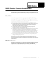
9000 Series
1. 9000 Series Sensor Installation
This manual shows you how to install the 9000 series sensors. It is intended for anyone who
installs or maintains a predictive maintenance system with permanently mounted sensors.
Introduction
A sensor (also called a transducer) is a device that measures a physical quantity and
converts it into a proportional electrical signal, typically voltage or current. This signal is
sent through a cable to a central monitoring station. There the signal is converted into a
measurement with meaningful units. For example, the voltage signal from an accelerometer
is converted into a measurement with units of acceleration.
In order for a sensor to function correctly and accurately, several things must be true:
!
It must be mounted correctly. For an accelerometer, the best method is to bolt or stud
mount the sensor at the correct location on the machine. Adhesive mounting is a
suitable option when stud mounting is not feasible.
!
The cable must be able to carry the signal without degrading the signal at the
frequencies of interest over the length of the cable.
!
The cable must be correctly connected to the monitoring device. In some cases, this is a
station where the signal may be processed and tested against one or more alarm
setpoints. In addition, the monitoring device may convert the signal for transmission
over a network. Monitoring devices include data collectors, Enwatch™ units, 6600
Series Protection Monitors, XM™ series, Entrx®, and other vibration analysis systems.
!
Proper grounding techniques must be observed at all times, and particularly when
running a cable through a junction box.
This manual covers sensors, permanent mounting, and cable installation. Refer to the
specific monitoring device manual for information about connecting the sensor signal to the
monitoring device.
9000 Series Sensors
The 9000 series accelerometers cover a wide range of applications including low frequency
(less than 0.1 Hz or 6 CPM), high frequency (up to 30 kHz or 1500 kCPM), high
temperature (over 250° C), and velocity output (internal integrator). The following table
lists the sensors and characteristics.
Entek 9000 Series Sensor Installation Guide
1
9000 Series Sensors
Model
Number
Part
No
Bias
Output
Sensitivity
Description
Notes
General Purpose
9000A 43781I 8–12 VDC
100 mV/g General purpose
accelerometer
Top exit, Mil Spec connector.
6–8 VDC
100 mV/g General purpose
accelerometer
Top exit, Mil Spec connector.
Low bias voltage (6–8 V).
9000B 43782I 8–12 VDC
100 mV/g General purpose
accelerometer
Top exit, integral cable 10',
2-conductor shielded,
polyurethane jacket.
9008 46255I 8–12 VDC
100 mV/g Low cost general
purpose accelerometer
Top exit, integral cable 10',
2-conductor shielded,
polyurethane jacket.
9100 43784I 8–12 VDC
100 mV/g General purpose
precision accelerometer
Top exit, Mil Spec connector.
9000A-LBV 43783I
9100AT 43810I 8–12 VDC
9100CSA 43786I 8–12 VDC
100 mV/g General purpose
precision accelerometer
Top exit, Mil Spec connector.
Intrinsic Safety Certification
by Canadian Standards
Association.
9100EX 43787I 8–12 VDC
100 mV/g General purpose
precision accelerometer
Top exit, Mil Spec connector.
Intrinsic Safety Certification to
CENELEC EEx ia iic T4.
9100FM 43785I 8–12 VDC
100 mV/g General purpose
precision accelerometer
Top exit, Mil Spec connector.
Intrinsic Safety Certification
by Factory Mutual.
9200 47086I 8–12 VDC
100 mV/g General purpose,
precision low profile
ring style accelerometer
Side exit, Mil Spec connector.
9200AT 43811I 8–12 VDC
9200CSA 43790I 8–12 VDC
9200EX
2
Top exit, Mil Spec connector.
100 mV/g General purpose
10 mV/°C precision accelerometer,
temperature sensor
43791 8–12 VDC
Side exit, Mil Spec connector.
100 mV/g General purpose,
10 mV/°C precision low profile
ring style accelerometer,
temperature sensor
100 mV/g General purpose,
precision low profile
ring style accelerometer
Side exit, Mil Spec connector.
Intrinsic Safety Certification
by Canadian Standards
Association.
100 mV/g General purpose
precision accelerometer
Side exit, Mil Spec connector.
Intrinsic Safety Certification to
CENELEC EEx ia iic T4.
Entek 9000 Series Sensor Installation Guide
9000 Series Sensors
Model
Number
Part
No
Bias
Output
Sensitivity
Description
Notes
9200FM 43789I 8–12 VDC
100 mV/g General purpose,
precision low profile
ring style accelerometer
Side exit, Mil Spec connector.
Intrinsic Safety Certification
by Factory Mutual.
9300 43792I 8–12 VDC
100 mV/g Low cost accelerometer
Top exit, Mil Spec connector.
9400 47090I 8–12 VDC
100 mV/g General purpose, low
profile side exit
accelerometer
Side exit, Mil Spec connector.
9100L 43794I 8–12 VDC
500 mV/g Low frequency
accelerometer
Top exit, Mil Spec connector.
9200L 43795I 8–12 VDC
500 mV/g Low frequency, low
profile ring style
accelerometer
Side exit, Mil Spec connector.
6–9 VDC
500 mV/g Low frequency
accelerometer
Top exit, Mil Spec connector.
9500HLF 43797I 8–12 VDC
1000 mV/g Low frequency
accelerometer
Top exit, Mil Spec connector.
Low Frequency
9500LF 43796I
9600 43798I 8–12 VDC
10 V/g Ultra low frequency
accelerometer
Top exit, Mil Spec connector.
High Frequency
9700A 43799I 8–12 VDC
10 mV/g High frequency
accelerometer
Top exit, 5-44 microdot
connector.
9700B 43800I 8–12 VDC
100 mV/g High frequency
accelerometer
Side exit, 10-32 coaxial
connector.
9900A 43802I 8–12 VDC
100 mV/g Triaxial accelerometer
with positioning pin
Side exit, Mil Spec 4-pin
connector.
9900B 43803I 8–12 VDC
100 mV/g Triaxial accelerometer
with positioning pin
Side exit, integral cable 10',
4-conductor shielded,
polyurethane jacket.
Triaxial
Entek 9000 Series Sensor Installation Guide
3
9000 Series Sensors
Model
Number
Part
No
Bias
Output
Sensitivity
Description
Notes
High Temperature
9100T 43805I 8–14 VDC
9150HT 43807I 12–15 VDC
9150HTA
46496 12–15 VDC
9200T 43806I 11–14 VDC
100 mV/g High temperature
accelerometer
Top exit, Mil Spec connector,
-54 to 163 deg C operating
range.
100 mV/g High temperature charge Top exit, 2-Pin Mil Spec
mode accelerometer
connector, -54 to 260 deg C
system
operating range.
100 mV/g High temperature charge Top exit, 2-Pin Mil Spec
mode accelerometer
connector, -54 to 260 deg C
system
operating range. Armored
cable.
100 mV/g High temperature, low
profile ring style
accelerometer
Side exit, Mil Spec connector,
-54 to 163 deg C operating
range.
Velocity Output
4
9100VO 43808I 8–12 VDC 100 mV/in/sec Velocity output
accelerometer
Top exit, Mil Spec connector.
9200VO 43809I 8–12 VDC 100 mV/in/sec Velocity output, low
profile ring style
accelerometer
Side exit, Mil Spec connector.
Entek 9000 Series Sensor Installation Guide
Sensor Mounting
Sensor Mounting
Next to choosing the correct sensor, the sensor mounting is the most important
consideration in getting accurate readings from the sensor.
Types of Sensor Mounting
The actual frequency range of a sensor depends on how well it is attached to the machine.
Mounting sensors directly on the case
Mounting sensors directly to the machine is the most common mounting technique for many
vibration sensors. Sensors designed for stud mounting have a base that is drilled and tapped
for that purpose. There are two common methods of stud mounting a sensor. In both cases, it
is crucial to prepare a flat, smooth, and clean area at least as large as the base of the sensor.
If the surface is not prepared properly, some of the vibration energy will be lost, and will not
be transmitted to the sensor. Improper mounting can also allow chatter, creating false data.
Note: Entek recommends following the API 670 requirements for surface finish and flatness, even
for non-API installations. If the surface is not properly prepared, it can reduce the detection
of higher frequencies.
1.
The first method is to spot face the surface, then drill and tap a hole in the machine case
or bearing housing where you want to install the sensor. Per the requirements of API
670 Appendix C.2.1, the surface finish should be within 0.8 micrometers (.032 mil, or
32 µinches) and the flatness should be below 25 micrometers (1 mil).
2.
Clean the finished area to remove any rust, dirt, paint, or grease.
3.
Insert a set screw leaving enough of the screw above the case to attach the sensor,
typically 1/4 inch. Some sensors come with captive mounting screw and do not need a
separate set screw.
4.
Apply a thin coating of grease or silicone lubricant to the surface.
5.
Use a torque wrench to attach the sensor. Refer to the following table.
Entek 9000 Series Sensor Installation Guide
5
Sensor Mounting
Follow the specific sensor’s guidelines for the dimensions of the hole, the type of set screw,
and the torque for attaching the sensor. The table below lists the data for the 9000 sensors.
Sensor
Screw Type
Hole Depth
Torque
9100 Series
1/4-28 stud
3/8 inch
26 inch-pounds
9200 Series
1/4-28 captive screw
3/8 inch
30 inch-pounds
9300 Series
1/4-28 stud
3/8 inch
26 inch-pounds
9400 Series
1/4-28 captive screw
3/8 inch
30 inch-pounds
9500 Series
1/4-28 stud
3/8 inch
26 inch-pounds
9600 Series
3/8-16 stud
1/2 inch
60 inch-pounds
9700A
5-40 stud
3/8 inch
12 inch-pounds
9700B
10-32 stud
3/8 inch
20 inch-pound
Note: For 3/8 deep holes, make sure 1/4 inch of the stud engages the base of the sensor. If you
screw a 1/2 inch stud fully into a 3/8 inch deep hole, that leaves only 1/8 inch of stud to hold
the sensor, which is not sufficient.
The second method is to drill through the machine case or housing, and use a machine screw
to secure the sensor. Spot face the surface, then drill the hole in the machine case or bearing
housing where you want to install the sensor. Follow the sensor’s guidelines for the
dimensions of the hole, the type of machine screw, and the torque for attaching the sensor.
Mounting sensors on an insulated housing
In some cases, the sensor is mounted on an insulated housing that cannot or should not be
grounded. For this type of installation, we recommend that you use a sensor with a groundisolated case. Many of the 9000 Series sensors have ground-isolated cases. Note that the
9700 does not have isolated case. The 9700B and 9150HT are base isolated, not case
isolated. Contact Rockwell Automation Integration Condition Monitoring Technical
Support for more information on the Entek sensors.
6
Entek 9000 Series Sensor Installation Guide
Sensor Mounting
When connecting cables for sensors with ground-isolated cases, make sure that the cable
shield is not grounded at the sensor end. There are two possible cable configurations:
!
In coaxial cable, the center conductor carries the signal and power, while the outer braid
provides shielding and signal return. Grounding the shield at the monitoring device and
not at the sensor isolates the sensor and prevents ground loops.
!
In cable with two wires and shield, the signal and power are carried on one lead and the
signal return on the other lead. The outer braid provides shielding. To isolate the sensor
and prevent ground loops, ground the shield at the monitoring device.
Note: It is very important to properly ground the cable shield. Failing to do so can result in
interference with the signal and possible damage to the sensor in high electromagnetic
interference/electrostatic discharge environments.
Mounting sensors with adhesive
If a mounting hole cannot be drilled into the machine surface, you can mount the sensor
using adhesive. There are two ways to do this: you can mount the sensor directly to the
machine; or you can mount a flat plate with a threaded stud, and attach the sensor to the
stud. Note that mounting the sensor using adhesive may limit the detection of high
frequencies. Suggested adhesives are listed in the following table.
Adhesive
Comments
Loctite 325 with 707
Activator
Cyanoacrylate adhesive. Single component; sets up quickly; use
at temperatures below 200° F; surface must be clean and smooth,
and remove by twisting the sensor.
Versilok 406–Lord
Chemical Products
Structural adhesive. Water resistant; useful to 250° F; cures to
full properties at room temperature in 24 hours.
Note: Entek recommends following the API 670 requirements for surface finish and flatness, even
for non-API installations. If the surface is not properly prepared, it can reduce the detection
of higher frequencies.
1.
Spot face the surface on the machine case or bearing housing where you want to install
the sensor. Per the requirements of API 670 Appendix C.2.1, the surface finish should
be within 0.8 micrometers (.032 mil, or 32 µinches) and the flatness should be below 25
micrometers (1 mil).
2.
Prepare the surface following standard adhesive bonding practice. Abrade and then
thoroughly clean the spot on the machine with solvent.
3.
Mix the adhesive according to its directions.
4.
Attach the sensor or plate to the machine.
5.
Allow the recommended time for the adhesive to cure.
6.
Make sure the sensor is grounded through the cable shield to a good electrical ground.
Entek 9000 Series Sensor Installation Guide
7
Sensor Mounting
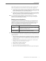
Mounting sensors with a bracket
Sometimes a sensor will not fit at the desired location on or near the bearing housing
because of an obstruction or because a suitable flat surface is not available. In these cases, it
may be necessary to use a bracket extending from the desired measurement point to an area
where the sensor can be mounted properly.
Make sure that the bracket itself does not introduce any extraneous vibrations. The bracket
must not bend or flex. Even a small amount of flexing in the bracket may result in unreliable
readings. Only a stiff bracket is able to transfer the vibration from the machine to the sensor
without adding vibration due to the natural resonance frequency of the bracket. As a general
rule, even the shortest bracket will require fabrication from 1/2-inch steel plate.
Machine housing
Gussets
All brackets should be tested for resonance in the frequencies that the sensor will monitor. If
possible, the bracket design should be approved by your sensor or system supplier. Contact
Technical Support for assistance.
8
Entek 9000 Series Sensor Installation Guide
Sensor Cable Guidelines
Sensor Cable Guidelines
This section describes some common cable guidelines to get the signal from the sensor to
the monitoring device.
Sensor Connections and Power
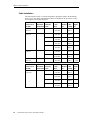
Most of the 9000 series sensors are two-wire, IEPE accelerometers. There are also 9000
series sensors that have a built-in integrator to produce a velocity signal, as well as
combination accelerometer/temperature sensors. The pin connections on the sensors are
listed in the following table.
Connector Pin Function
Shell
Ground, connected to cable shield
A
IEPE sensor power and signal
B
IEPE sensor signal return (signal common)
A
Side View
B
End View
Combination accelerometer/temperature sensors have three pins.
Connector Pin Function
Shell
Ground, connected to cable shield
A
IEPE sensor power and signal
B
IEPE sensor signal return (signal common) and temperature common
C
Temperature sensor signal and power
A
Side View
B
C
End View
Entek 9000 Series Sensor Installation Guide
9
Sensor Cable Guidelines
Cable Installation
The cable from the sensor is a critical component in getting the signal to the monitoring
device. The 2-wire cables with shield listed below are dedicated, one per sensor, to carry
sensor signals to the monitoring device.
Cable run at
10 kHz
Cable
diam.
Belden
No.
Max. Alpha
Temp. No.
Up to 500 ft
(152 m)
6 dB (2:1)
1
0.168 in
4.27 mm
8641 140° F
60° C
2400C
Up to 500 ft
(152 m)
12 dB (4:1)
1
0.175 in
4.45 mm
8761 140° F
60° C
2401C
3
0.310 in
7.87 mm
8777 176° F
80° C
6010C
6
0.390 in
9.91 mm
8778 176° F
80° C
6012C
12
0.480 in
12.2 mm
9768 176° F
80° C
6017C
3
0.370 in
9.40 mm
9730 140° F
60° C
6073C
6
0.480 in
12.12 mm
9731 140° F
60° C
6076C
12
0.660 in
16.7 mm
9734 140° F
60° C
6079/
12C
Up to 1000 ft
(304 m)
Up to 1500 ft
(457 m)
Cable run at
10 kHz
Up to 4000 ft
(1219 m)
10
No. of
Maximum channels/
attenuation cable
6 dB (2:1)
12 dB (4:1)
No. of
Maximum channels/
attenuation cable
6 dB (2:1)
Entek 9000 Series Sensor Installation Guide
Cable
diam.
Belden
No.
Max. Alpha
Temp. No.
1
0.204 in
5.18 mm
8762 140° F 2411C
60° C
3
0.340 in
8.64 mm
9873 176° F 6033C
80° C
6
0.430 in
10.9 mm
9874 176° F 6036C
80° C
12
0.590 in
15.0 mm
9877 176° F 6042C
80° C
Sensor Cable Guidelines
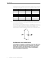
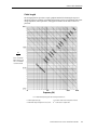
Cable length
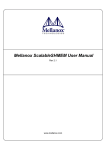
The nomograph below provides a simple, graphical method for obtaining the expected
maximum frequency capability of an IEPE measurement system. The maximum peak signal
voltage amplitude, cable capacitance, and supplied constant current must be known or
presumed.
V
Ic - 1
(Rate of Maximum
Output Voltage from
Sensor to Available
Constant Current)
Frequency (Hz)
fmax = Maximum frequency given the following characteristics
C = Cable capacitance (pF)
V = Maximum output voltage from sensor (volts
Ic = Constant current level from power unit (mA)
109 = Scale factor to equate units
Entek 9000 Series Sensor Installation Guide
11
Sensor Cable Guidelines
For example, when running a 100ft. cable with a capacitance of 30 pF/ft, the total
capacitance is 3000 pF. This value can be found along the diagonal cable capacitance lines.
Assuming the sensor operates at a maximum output range of 5 volts and the constance
current signal conditioner is set at 2 mA, the ratio on the vertical axis can be calculated to
equal 5. The intersection of the total cable capacitance and this ratio result in a maximum
frequency of approximately 10.2 kHz.
The nomograph does not indicate whether the frequency amplitude response at a point is
flat, rising, or falling. For precautionary reasons, it is good general practice to increase the
constant current (if possible) to the sensor (within its maximum limit) so that the frequency
determined from the nomograph is approximately 1.5 to 2 times greater than the maximum
frequency of interest.
Reducing electrical interference
The small electrical signal coming from a sensor can be affected by electrical interference.
Make every effort to reduce the electrical interference in cables to the lowest acceptable
levels. Interference can come from many sources, including power cables, switching
devices, motor controllers, walkie-talkies, robot transmitters, arc welders, induction heating
equipment, motors, and high voltage ignition systems.
The following methods are effective for minimizing electrical interference:
12
!
Use twisted pair wires in each cable.
!
Use individual foil shields around each pair, with a shield drain wire grounded at only
one point for each shield. Do not ground the shield at both ends of the cable. Grounding
the cable shield at both ends causes a “ground loop.” This can cause interference
because in most cases the ground potential differs at the two ends.
!
Electrically isolate (insulate) each sensor circuit from all others.
!
Surround all cables with grounded steel conduit where possible.
!
Do not use conduits containing sensor cables for any other circuits.
!
Avoid running 9000 series sensor cables parallel to other cables, such as non-9000
series sensor, or communication cables.
!
Avoid running sensor cables parallel to power wiring. When this cannot be avoided,
make sure that sensor cables are at least 12 inches away from all power wiring carrying
120 V or less. For power circuits of 120–240 V, the minimum spacing is 24 inches. For
circuits of 480 V or higher, the minimum spacing is 48 inches.
!
If the cable must cross power wiring, maintain the above spacing between the wires.
Cross the wires at a right angle (90°) to minimize interference.
!
Make sure the cable is securely fastened to reduce low frequency noise from cable
movement. This is particularly important at the sensor end of the cable.
Entek 9000 Series Sensor Installation Guide
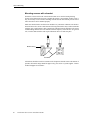
Sensor Cable Guidelines
For a sensor with a top exit cable connection, make sure there is at least 6 inches of
clearance above the machine surface to allow for movement of the sensor and cable.
Clamp the cable within 6 inches of the sensor, allowing enough room for the cable to
bend without damage. Clamp the cable at intervals to prevent movement.
Service loop
Cable clamp
Machine surface
For sensors with a side exit cable connection, clamp the cable 3–4 inches from the
sensor. Clamp the cable at intervals to prevent movement.
Service loop
Machine surface
Fixed surface
Cable construction
The sensor cable should be twisted pair with its own foil shield. Do not ground the cable
shield drain wire at both ends. The shield connections should be carried through any
junction boxes without connecting to a ground or other shields.
If the end of the sensor cable is in a location where it will be splashed or hosed down, coat it
with RTV silicone rubber sealant to prevent fluids from entering the cable.
!
At the sensor end, use RTV in and around the connector and cable entry to the
connector.
!
At the opposite end to the sensor, terminate the cable in a NEMA housing using proper
cable entry connectors that create a tight seal around the cable and the entry hole of the
housing.
Entek 9000 Series Sensor Installation Guide
13
Sensor Cable Guidelines
Splicing cables
Splices in cables are acceptable if the connections are soldered. Splices must be located in a
junction or conduit box for access. Coil any excess cable in the junction or conduit box,
making sure that any exposed (bare) cable shield is taped off so it cannot touch the junction
or conduit box. If necessary, you can shorten the armored cable from an accelerometer or
velocity sensor by carefully cutting away the armor. Grind or file the cut armor to remove all
sharp edges.
Cable Conduit Guidelines
All signal wiring should be run in grounded conduit, where it is protected from damage and
external influences. The conduit must be installed with proper drain points so that water
from condensation and other sources does not build up around the cable.
Cables in conduit
When cables are run in steel conduit, the conduit must be grounded per NEC and local code
requirements. Where necessary, flexible interlocked steel conduit can be used. Note that
flexible conduit is not as effective against RF/EM interference as solid conduit. No wires or
cables other than sensor wires or cables should be run in the same conduit.
In high humidity areas, outdoors, or where the sensor may get wet, the conduit should be
protected to prevent water from entering. If the conditions could cause condensation in the
conduit, use rigid metallic conduit or liquid-tight flexible conduit with suitable fittings.
The “far” end of the conduit should be protected to prevent water from entering. Provide
appropriate condensate drains at low points in the conduit runs to allow condensation to
escape.
If a water-resistant seal is required, you can also use pipe joint sealing compound on fittings
before screwing connectors to the sensor body. Coat the terminal strip inside the junction
box with RTV silicone rubber after the cables are connected. Do not use sealant on the
gasket surfaces.
Conduit runs to panels
Make sure the conduits are large enough to accommodate the signal cables plus space for
servicing. The maximum acceptable cable length from sensor to monitoring device depends
on the type of sensor, the frequencies of interest, the grade of cable, and the monitoring
device. Follow the manufacturer’s specifications for cable length and grade, or refer to the
table under “Cable Installation” on page 10.
Conduit boxes
Use a conduit or junction box to protect any connections or splices in the sensor cable.
14
!
In wet areas, use NEMA-4X rated box. You can also use a 1/2 or 3/4-inch trade size
conduit body with gasketed cover, mounted vertically to prevent water entry into the
box.
!
Locate the conduit box so that 1–2 inches of cable from the sensor extends into the box.
!
Use rigid thin wall or liquid-tight flexible conduit on the output cable.
!
Ground the box and conduit to avoid electrical and radio frequency interference.
Entek 9000 Series Sensor Installation Guide
Connecting 9000 Series Sensors to Monitors
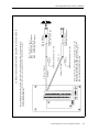
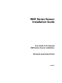
Connecting 9000 Series Sensors to Monitors
This following drawings show the connections between 9000 series sensors and the
following types of monitors: 5800 monitors, 6600 monitors, XM modules, and Enwatch
units. These show the most common connections. Refer to the manual for your particular
monitor for the wiring specific to your monitor.
Entek 9000 Series Sensor Installation Guide
15
16
Entek 9000 Series Sensor Installation Guide
Common
Shield
Shield
Channel B Signal
This shows a dual-channel card. For single-channel
card, only wire in top channel
Cable shield not
connected at this end
Pin A - Signal
Pin B - Common
Common
Channel A Signal
Note: If shield is connected at the transducer, do not
ground the shield at the 5800 monitor end. If shield
connection is unknown at the two pin connector,
ohm out and verify before wiring.
Cable shield not
connected at this end
Pin A - Signal
Pin B - Common
10 SIG AND +24 VCD
9
8 SIG GND COMMON
7
6
5 0-5 VDC RECORDER CHAN B
4 GND
3 4-20 MA CURRENT TRANSMITTER CHAN B
2 +24 VDC
1 ANALYZER CHAN B
10 ANALYZER CHAN A
9 -24 VDC
8 4-20 MA CURRENT TRANSMITTER CHAN A
7 GND
6 0-5 VDC RECORDER CHAN A
5
4
3 SIG GND COMMON
2
1 SIG AND +24 VDC
CONNECTING 9000 SERIES TRANSDUCERS TO A 5800 MONITOR
Connecting 9000 Series Sensors to Monitors
25
26
27
28
29
30
31
32
33
34
35
36
37
38
39
40
41
42
43
44
45
46
47
48
1
2
3
4
5
6
7
8
9
10
11
12
13
14
15
16
17
18
19
20
21
22
23
24
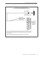
Shield
Cable shield not
connected at this end
Cable shield not
connected at this end
Note: If shield is connected at the transducer, do not
ground the shield at the 6600 monitor end. If shield
connection is unknown at the two pin connector,
ohm out and verify before wiring.
Ground at 6600 monitor rack
Shield
Common
Ground at 6600 monitor rack
Channel 2 Signal
Common
Channel 1 Signal
Pin A - Signal
Pin B - Common
6600 Monitor Pin Inputs
Pin 1 Channel 1 Input Signal
Pin 2 Signal Common
Pin 3 Channel 2 Input Signal
Note: IEPE transducers require constant current diodes attached to the backplane,
one per active channel. Refer to Reference Drawing A39588+ for E39588 constant
current diode assembly.
CONNECTING 9000 SERIES TRANSDUCERS TO A 6600 MONITOR
Connecting 9000 Series Sensors to Monitors
Entek 9000 Series Sensor Installation Guide
17
Connecting 9000 Series Sensors to Monitors
C O N N E C T IN G 9 0 0 0 S E R IE S IE P E A C C E L E R O M E T E R T O A N E N W A T C H U N IT
RX
TX
J8
LK
J11
OB
J9
RS-232
DB-9 (female)
Status LED's
_
+
DC Power In
Network Input
RJ-45 Jack
J6
JP 20
3
1
U28
J5
3
JP 19
U20
1
J4
3
JP 18
Mode Select
1
J3
3
2
JP 17
1
RV2
RV3
RV1
A-B
A-B
A-B
A-B
A-B
A-B
A-B
A-B
A-B
A-B
A-B
A-B
A-B
A-B
A-B
J u m p e r i n x A p o s it io n
f o r IE P E A c c e le r o m e te r
1-2-3-4-5-6-7-8
9-10-11-12-13-14-15-16
1-2-3-4-5-6-7-8
9-10-11-12-13-14-15-16
T e rm in a l 1 - S ig n a l
T e rm in a l 2 - G ro un d
S h i e l d G ro u n d
P in A - S ign al
P in B - G ro u n d
C a b le s h ie ld n o t
c o n n e c te d a t th is e n d
18
Entek 9000 Series Sensor Installation Guide
2
2
Normal / Monitor
A-B
3
2
JP 21
A-B
4
2
1
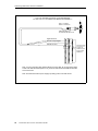
Connecting 9000 Series Sensors to Monitors
CONNECTING 9000 SERIES SENSORS
TO XM-120/121/122 VIBRATION MODULE CHANNEL 1
Pin A - Signal
Pin B - Common
Cable shield not
connected at this end
Signal Common
Channel 1 Input Signal
Shield Ground
16
0
37
21
22
5
6
Jumping terminals
5 to 6 & 21 to 22
configure the
transducer power
supply for IEPE
tranducer(s)
Note: You may ground the cable shield at either end of the cable. Do not ground the shield
at both ends. Recommended practice is to ground the cable shield at the XM terminal base
and not the sensor.
Note: The internal transducer power supply is providing power to the 9000 sensor.
Entek 9000 Series Sensor Installation Guide
19
Connecting 9000 Series Sensors to Monitors
TYPICAL WIRING FOR IEPE ACCELEROMETER
TO XM-120/121/122 VIBRATION MODULE CHANNEL 2
Pin A - Signal
Pin B - Common
Cable shield not
connected at this end
Channel 1 Input Signal
Signal Common
Channel 2 Input Signal
Shield Ground
17
38
21
22
1
5
6
Jumping terminals
5 to 6 & 21 to 22
configure the
transducer power
supply for IEPE
tranducer(s)
Note: You may ground the cable shield at either end of the cable. Do not ground the shield
at both ends. Recommended practice is to ground the cable shield at the XM terminal base
and not the sensor.
Note: The internal transducer power supply is providing power to the 9000 sensor.
20
Entek 9000 Series Sensor Installation Guide
Index
Index
H
5800 monitors 15
6600 monitors 15
high frequency sensors 3
high temperature sensors 4
A
I
adhesive mounting 7
attenuation, signal in cable 10
insulated mounting 6
interference, reducing 12
B
J
Belden number, cable 10
bracket mounting sensors 8
junction boxes 14
C
cable
coaxial 7
conduit 14
conduit boxes 14
construction 13
guidelines 9
installation 10
length 10, 11
reducing electrical interference 12
splicing 14
coaxial cable 7
conduit 14
conduit boxes 14
connecting
5800 monitors 15
6600 monitors 15
Enwatch unit 15
XM modules 15
connections, sensors 9
L
low frequency sensors 3
M
mounting sensors
adhesive 7
brackets 8
insulated housing 6
overview 5
set screws 6
stud 5
torque 6
O
overview, sensors 1
R
reducing electrical interference 12
E
Enwatch unit 15
G
general purpose sensors 2
Entek 9000 Series Sensor Installation Guide
3
Index
S
sensors
connections 9
general purpose 2
high frequency 3
high temperature 4
low frequency 3
mounting 5
mounting on an insulated housing 6
mounting with a bracket 8
mounting with a stud 5
mounting with adhesive 7
overview 1
triaxial 3
velocity output 4
set screws 6
splicing cable 14
T
torque, sensor mounting 6
transducers
See sensors
triaxial sensors 3
V
velocity output sensors 4
X
XM modules 15
4
Entek 9000 Series Sensor Installation Guide