1
SAVE THIS MANUAL
FOR FUTURE
REFERENCE
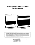
SEARS
owners
manual
MODEL NO.
113.244513
Serial
Number
Model and serial
number may be found
at the right-hand side
of the frame.
You should record both
model and serial
number in a safe place
for future use.
CAUTION:
Read GENERAL and
ADDITIONAL SAFETY
IN ST R UCTIO N S
caref ully
CRRFTSMf,]I
7O-rNcH
BAND SAW
o assem bly
o operating
o repait parts
Sold by SEARS, ROEBUCK AND CO., Chicago, IL. 60684 U.S.A.
Part No. SP5100
FULL ONE YEAR WARRANTY ON CRAFTSMAN BAND SAW
lf within one year lrom the date of purchase, this Craftsman Band Saw fails due to a defect
in
free
charge.
it,
of
repair
will
Sears
material or workmanship,
WARRANTY SERVICE IS AVAILABLE BY SIMPLY CONTACTING THE NEAREST SEARS SERVICE
CENTER/DEPARTMENT THROUGHOUT THE UNITED STATES.
THIS WARRANTY APPLIES ONLY WHILE THIS PRODUCT IS USED IN THE UNITED STATES.
This warranty gives you specilic legal rights, and you may also have other rights which vary from
state to state.
SEARS, ROEBUCK AND CO.,698/731A, Sears Tower, Chicago, lL 60684
general safety instructions for power tools
1.
at all times. Everyday eyeglasses only
have impact resistant lenses, they are NOT
safety glasses. Also, use face or dust mask if
cutting operation is dusty, and ear protectors
(plugs or muffs) during extended periods of
287.1)
KNOW YOUR POWER TOOL
Read and understand the owner's manual and
labels aff ixed to the tool. Learn its application
and limitations as well as the specif ic potential
hazards peculiar to this tool.
GROUND ALL TOOLS
This tool is equipped with an approved 3conductor cord and a 3-prong grounding type
plug to f it the proper grounding type receptacle.
The green conductor in the cord is the grounding wire. Never connect the green wire to a llve
terminal.
KEEP GUARDS IN PLACE
working order, and in proper adlustment
- inalignment.
and
13. SECURE WORK
Use clamps or a vise to hold work when practical. lt's safer than using your hand, f rees both
hands to operate tool.
before turning it on.
14. DON'T OVERREACH
Keep proper footing and balance at all times.
15. MAINTAIN TOOLS WITH CARE
Keep tools sharp and clean for best and safest
oerformance. Follow instructions for lubricating
and changing accessories.
16. DISCONNECT TOOLS
before servicing; when changing accessories
such as blades, bits, cutters, etc.
KEEP WORK AREA CLEAN
17. AVOID ACCIDENTAL STARTING
REMOVE ADJUSTING KEYS AND WRENCHES
Form a habit of checking to see that keys and
adjusting wrenches are removed from tool
Cluttered areas and benches invite accidents.
Floor must not be slippery due to wax or sawd
6.
ooeratlon.
ust.
AVOID DANGEROUS ENVIRONMENT
Don'l use power tools in damp or wet locations
or expose them to rain. Keep work area well
lighted. Provide adequate surrounding work
7.
soace.
KEEP CHILDREN AWAY
8.
worK area.
MAKE WORKSHOP CHILD.PROOF
9.
moving starter keYs.
DON'T FORCE TOOL
re-
It will do the job better and safer at the rate for
which it was designed.
10. USE RIGHT TOOL
Don't force tool or attachment to do a job it was
not designed for.
11. WEAR PROPER APPAREL
Do not wear loose clothing, gloves, neckties or
jewelry (rings, wristwatches) to get caught in
moving parts. NONSLIP footwear is recommended. Wear protective hair covering to con'
tain long hair. Roll long sleeves above the
elbow.
12. USE SAFETY GOGGLES (Head Protection)
Wear safety goggles (must comply with ANSI
is in "OFF" position
before
plugging in.
't8. USE RECOMMEN DED ACCESSORIES
Consult the owner's manual for recommended
accessories. Follow the instructions that
accompany the accessories. The use of improper accessories may cause hazards.
19.
All visitors should be kept a safe distance f rom
with oadlocks, master switches, or by
Make sure switch
NEVER STAND ON TOOL
Serious injury could occur if the tool is tipped
or if the cutting tool is accidentally contacted.
Do not store materials above or near the tool
such that it is necessary to stand on the tool to
reach them.
20. CHECK DAMAGED PARTS
Before further use of the tool, a guard or other
part that is damaged should be caref ully check-
ed to ensure that it will operate properly and
perform its intended f unction. Check for align'
ment of moving parts, binding of moving parts'
breakage of parts, mounting' and any other con'
ditions that may affect its operation' A guard or
other part that is damaged should be properly
repaired or rePlaced.
21. NEVER LEAVETOOL RUNNING UNATTENDED
Turn oower off . Don't leave tool until it comes to a
complete stoP.
additional safety instructions for band saw
Safety is a combination of common sense, staying alert,
d.
Do not do layout, assemble, or set up work on
the table while the saw is running.
h
Wear safety goggles (not glasses) that comply
and knowing how your band saw works.
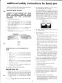
BEFORE USING THE SAW:
with ANSI 287.1 (shown on package). Using any
power tool can result in foreign objects berng
thrown into the eyes, which can result in permanent eye damage. Safety goggles are available
at Sears retail or catalog stores. Use of glasses
or use of goggles not in compliance with ANSI
WARNING: TO AVOID MISTAKES THAT COULD
RESULT IN SERIOUS, PERMANENT INJURY
DO NOT PLUG THE SAW IN UNTIL THE FOLLOW.
ING STEPS HAVE BEEN
SATTSFACTORILY
COMPLETED:
287.1 could result in severe injury f rom breakaqe
of the eve orotection.
1. Assembly and alignment.
2. l-earn the function and proper use of the on-off
switch. upper blade guide locx knob lower blade
guide tension adlusting knob table iock knobs,
bevel scale, guide. bar lock knob and blade thrust
bearing adjustment
a sa{et; nstructions and
oneratino nrncedr rres tniO!ChOUi tfte manUal.
Fead the followrng iaoe s ,,,i..n appear on the front
of the band say,1 anc o ace c.ra:o
3. Read and undersiand
4.
For dusty operaticns, wear a face shreld alonq
with safety goggles
Use extra caution with larqe, verv small, or awkward workpieces
FoF youR owN sAFEry:
f-oANGER I
READ ANO UNDERSTAND OWNER S
r ALWAYSTRSfE-a6G,E5r€p^\SJ.
a.[€ lUFvffim^!*Cm€rffiaL&
3 rrEA6 nsE6 l SgE FlrcE
AWA!
'
! r!f!rcffntrftEtrtFCcaltAuruL
ia!F9&yA6!6rruraf,€
3€ l-EfrE
ro jE CW-F ECCtS |lmrc €rc 6
aa- ri r*f, 6 Jffi
ti stot ALLd ttl* rc
s-e t€Frt aEtfrs Jl|*o Ftc!
1
^'^-n*3 wi melirc Hs r^G,N€
l€Mlqt9l*lL^*
s s.^--€:e{4.,'
r€frrcruffirac-cilra-iE-rt.E
a€Ffff ffiN^nrc r&{r
aF,s! la $Rf trc pq
r|i*
!!rx 5J:rs
^r:E a.€. riE
r:e
1ffi3
AA!
iLr
^1!s'E: 3E
. ALrlYslA6r JE. 5J* Sa r-r. - ,_S- :-E^6
2
ltAr'!G
Y
1.
MANUAL EEFONE OPERANTJG THls MACTIINE:
E
2.
Rl
.1e$:
blade.
3.
3EFCFE
i]JUST
NG
WHEN INSTALLING OR MOVING THE
SAW
4.
1. To avoid in,ur',' i':m unexpected saw movement:
a. Bolt or c amp:l'e sarv to a sturdy level workbench
c.
U-
Adjust the sa,'. =r the table is level and the saw
ooes nol roc(
Bolt the bench or stand to the floor if it tends to
slip. slide
o't
f
.
p c'.,er lurrng operations like cutting
rong, neavy D0arcs
d.
Turn saw off and unp ug electric cord before movIng the sa\ry to a new area.
2. Store
When cutting rrregularly shaped workpieces.
plan your work so it will not pinch the blade.
A piece of molding, for example, must lay flat
or be held by a fixture or jig that will not let rt
twist. rock or slip while being cut.
Properly support round material such as
dowel rods. or tubing. They have a tendency
to roll while being cut, causing the blade to
"bite. To avoid this, always use a "V" block,
or clamp the workpiece to a miter gauge.
or stand r','he"e :nere is pienty of room for feeding
the workcreae
b.
Use extra supports (tables. saw horses. etc.)
for any workpieces large enough to tip when
not held down to the table top.
Do not feed small pieces that require your
finger holding the workpiece to go under the
guard area Use jigs or fixtures to hold the
work and keep yours l-rands away from the
and use the band saw indoors.
3. Tre back long hair.
4. Roll long sleeves above
g.
BEFORE EACH USE
1, lnspect your saw. lf any part of this band saw is
missing, or bent, or failed in any way, or any electrical
components do not work properly, turn the saw off
'emove switch key. and unplug the saw. Replace
:amaged, missing. or farled parts before using the
To avoid risk of hearing damage. wear ear plugs
or muffs during extended periods of operation.
To avoid being suddenly caught in the blade
1. Do not wear gloves.
2. Remove all jewelry and loose clothing
the elbow.
To avoid injury from accidental starting. always
rrnolLro
""t ''Y saw trrrn switch off and remove switch
key before removing the guard. installing or removing any blade, accessory or attachment, or
making any adjustments
,
Y_
:a,'. again.
2
= .€3 :
.
:
)J" work to protect your eyes. hands. face,
ttodV.
h.
To avoid slips and jams causing rnjury:
1. Choose the right size and style blade for the
material and the type of cutting you plan to
do. Use this band saw to cut only wood, woodlike products and plastic.
2. Make
lf your saw makes an unfamiliar noise or if it
vibrates excessively, stop immediately. Turn the
sure the blade teeth point downward
toward the table.
3. Make sure the blade tracking guides
saw off . Remove switch key and unplug the saw.
and
Do not restart until finding and correcting the
thrust bearings are properly adjusted.
4. Always check and correctly adjust
problem.
blade
h
tension.
i.
Avoid awkward hand oositions where a sudden
slip could cause a hand to move into the blade.
To avoid accidental blade contact, minimize blade
2. Plan
Feed the workpiece only fast enough to let the
blade cut without bogging down or binding.
Before freeing jammed material. turn saw off . Remove switch key Remove plug from power
source outlet. Wait for all moving parts to stop.
j.
Make sure all clamps and knobs are tight and
there is no excessive play in any parts.
When backing up the workpiece, the blade may
bind in the kerf (cut) Thrs is usually caused by
sawdust clogging up the kerf or because the
blade comes out of the gurdes lf this happens:
k.
To avoid an electrical shock, make sure your fin-
1. Turn saw off.
breakage and provide maximum blade support.
1. Always adjust the upper blade guide and blade
guard to just clear the workpiece.
your hand placement so your fingers will
not be where a sudden slip could cause them
to hit the blade.
gers do not touch the metal prongs on the plug
when installing or removing the plug to or from
l.
2. Unplug saw.
3. Remove switch key.
4. Wait for all moving parts to stoo
5. Remove band saw cover.
6. Stick a flat blade screwdriver or wedqe
a live outlet.
Never turn your band saw "ON" before clearing
everything except the workpiece and related feed
or support devices off the table.
into
the kerf.
WHENEVER SAW IS RUNNING
7. Iurn the upper wheel by hand
WARNING: DO NOT ALLOW FAMILIARITY (GAINED
FROM FREQUENT USE OF YOUR BAND SAW) TO
CAUSE
A
using your palm
while backing up the workpiece.
Before removing loose pieces f rom the table. turn
saw off and wait for all moving parts to stop.
To avoid injury from untested or improper accessories, use only Recommended Accessories
listed on the Accessory page of this manual.
CARELESS MISTAKE. ALWAYS RE-
MEMBER THAT A CARELESS FRACTION OF A SECOND IS SUFFICIENT TO INFLICT SEVERE INJURY.
glossary of terms for woodworking
Beveling
Push Stick
An angle cutting operation through the face of the board.
A device used to feed the workpiece through the saw
Crosscut
A cutting operation made across the width of the
during narrow ripping type operations so the operator's
hands are kept well away from the blade.
workpiece.
Resaw
Compound Cutting
A simultaneous bevel and miter cutting operation.
A cutting operation to reduce the thickness of the workpiece to make thinner pieces.
FPM
Feet per minute. Used in reference to surface speed
of blade.
Freehand (as used for band saw)
Performing a cut without the workpiece properly supoorted on the work table.
Gum
A sticky, sap-based residue from wood products.
Kerf
The material removed by the blade in a through cut or
the slot produced by the blade in a non-through or
partial cut.
Leading End
The end of the workpiece which is pushed into the
cutting tool first.
Mitering
An angle cutting operation made across the width of
the workpiece.
Resin
A sticky, sap-based substance that has dried.
Ripping
A cutting operation along the length of the workpiece.
Sawblade Path
The area of the worktable or workpiece directly in line
with the saw blade.
Set
The distance the tio of the saw blade tooth is bent
outward from the face of the blade.
Trailing End
The workpiece end last cut by the saw blade
Workpiece
The item on which the cutting operation is being performed. The surfaces of a workpiece are commonly
referred to as faces, ends, and edges
Worktable
The surface on which the workpiece rests while perform-
ing a cutting operation.
y/
motor specifications and electrical
requirements
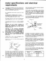
This machine is designed to use, and is equipped with,
a1725 RPM motor. lt is wired for operation on 120 volts,
60 Hz., alternating current. (TOOL MUST NOT BE CONVERTED TO OPERATE ON 230 VOLT).
For replacement motor refer to oarts list in this
manual.
This plug requires a mating 3-conductor grounded type outlet as shown.
lf the outlet you are planning to use for this
power tool is of the two prong type, DO NOT
REMOVE OR ALTER THE GROUNDING PRONG
lN ANY MANNER. Use an adapter as shown
below and always connect the grounding lug to a
known ground.
CONNECTING TO POWER SUPPLY OUTLET
This machine must be grounded while in use to
protect the operator from electric shock.
Plug power cord into a 120V properly grounded type
outlet protected by a 15-amp fuse or circuit breaker.
It is recommended that you have a qualif ied electrician replace the TWO prong outlet with a properly grounded THREE prong outlet.
GROUNDING LUG
lf you are not sure that your outlet is properly
grounded, have it checked by a qualif ied electrician.
WARNING: DO NOT PERMIT FINGERS TO
TOUCH THE TERMINALS OF PLUGS WHEN
INSTALLING OR REMOVING THE PLUG TO OR
SCREW
\
3-PRONG
\
MAKE SURE THIS IS
CONNECTED TO A
KNOWN GROUND
PLUG
FROM THE OUTLET.
WARNING: IF NOT PROPERLY GROUNDED
THIS POWER TOOL CAN CAUSE AN ELECTRI.
CAL SHOCK PARTICULARLY WHEN USED IN
DAMP LOCATIONS CLOSE TO PLUMBING. IF
AN ELECTRICAL SHOCK OCCURS THERE IS
THE POTENTIAL OF A SECONDARY HAZARD
SUCH AS YOUR HANDS CONTACTING THE
2-PRONG
RECEPTACLE
ADAPTER
lf power cord is worn or cut, or damaged in any
An adapter as illustrated is available for connecting plugs to 2-prong receptacles. The green
grounding lug extending from the adapter must
be connected to a permanent ground such as to
a properly grounded outlet box.
Your unit is for use on 120 volts, and has a plug that
looks like below
NOTE: The adapter illustrated is for use only if
you already have a properly grounded 2-prong
receptacle. Adapter is not allowed in Canada by
SAW BLADE.
way, have it replaced immediately.
the Canadian Electrical Code.
r-<t
qi'r"
PRONG
PROPERLY
GRO U N DED
3.PRONG OUTLET
\Y
This power tool is equipped with a 3-conductor
cord and grounding type plug which has a
grounding prong, approved by Underwriters'
Laboratories and the Canadian Standards Associatlon. The ground conductor has a green jacket
and is attached to the tool housing at one end
and to the ground prong in the attachment plug
at the other end.
The use of any extension cord will cause some
loss of power. To keep this to a minimum and to
prevent overheating and motor burn-out, use the
table below to determine the minimum wire size
(A.W.G.) extension cord.
Use only 3 wire extension cords which have 3prong grounding type plugs and 3-prong receptacles which accept the tools plug.
Lenglh of the
Conductor
Wire Sizes Required
(American Wire Gage Number)
120V Lines
0 - 25 Feet
26 - 50 Feet
No.
51 - 100 Feet
No.
16
No.'14
12
a-
contents
CONTENTS
powERTooLWARRANTY.... ..........2
GENERAL SAFETY INSTRUCTIONS FOR
POWER
......2
TOOLS
.....
Assembfy.
Alsembfy.
.....13
AdjustingTable
Knob
Cover Knobs
Blade Guides
Tension Lock Knob
Guide Bar Lock Knob .
Table Lock Knobs.....
Bevel Scale
On-OffSwitch
TensionAdjustment
5
UNPACKING AND CHECKING CONTEN S..... 6
ASSEMBLY
Mounting Band Saw to Workbench.... .. . .... '7
Clamping Band Saw to Workbench..... . ..... .8
........8
Installing the Table.
........9
lnstalling the Blade
. '. . .10
Tensioning the Blade.
.'......11
Blade
Tracking the
Adjusting the Table Square to Blade ......... 11
Adjusting Upper Blade Guide
Adjusting Upper Blade Guides
Adjusting UpperThrust Bearing
Adjusting Lower Blade Guide
........12
........13
Guides.
GETTING TO KNOW YOUR BAND SAW
ADDITIONAL SAFETY INSTRUCTIONS
..........3
FOR BAND SAW.
MOTOR SPECIFICATIONS AND ELECTRICAL
REQUIREMENTS
Adjusting Lower Blade
Drive Belt Tension
"'....--.12
--....".12
--..' '.12
BASIC BAND SAW OPERATION
Sawing
MAINTENANCE..
Lubrication
.......14
........14
.......14
.......14
....14
....14
.........14
......14
.......15
....16
.........16
RECOMMENDEDACCESSORIES.. ..... 16
..,...17
TROUBLESHOOTING
......18
REPAIR PARTS
.--.'."'12
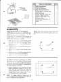
unpacking and checking contents
v
WARNING: FOR YOUR OWN SAFETY, NEVER
CONNECT PLUG TO POWER SOURCE OUTLET
UNTIL ALL ASSEMBLY STEPS ARE COMPLETE,
AND YOU HAVE READ AND UNDERSTAND THE
SAFETY AN D OPERATIONAL INSTRUCTIOI''IS.
#2
Model 113.244513 Band Saw is shipped complete
rn one carton.
Separate all parts from packing materials and
PHILLIPS SCREWDRIVEB
t\,4EDlUt'/ SCREWDRIVEB
tFrm-:
check each item with illustration and "Table of
Loose Parts". Make certain all items are accounted for, before discarding any packing material.
\-)-.
tu
+::@
1/2 INCH WRENCH
+g*t
HEX WFENCH
1/8 & 3/16
WARNING: IF ANY PARTS ARE MISSING, DO NOT
TRY TO ASSEMBLE THE BAND SAW PLUG IN THE
POWER CORD, OR TURN THE SWITCH ON UNTIL
THE MISSING PARTS ARE OBTAINED AND
IN-
STALLED CORRECTLY.
COt\,lBlNAT|ON S0UAFE l\,4UST BE TFUE
DRAW TIGHI
LINE ON BOAFD
ALONG THIS EDGE
STFAIGHT EDGE OF
BOARD 314'THICK
THIS EDGE |\4UST BE
PEFFECTLY STRAIGHT
az
SHOULD BE NO GAP OF OVEBLAP HERE WHEN
SQUAFF IS FLIPPED OVEF IN DOTTED POSITION
TABLE OF LOOSE PARTS
ITEM
Basic saw assembly
Owners Manual
Saw Table assembly
Bag Assembly Part #69181
Containing the following parts:
Switch, Key ..
Nut, Wing 114-20.
Screw, Truss Hd. 114-20 x 314.
Washer 17164 x5/8 x 1/16 . ....
Washer 17164 x 47164 x 1/16 . .
Indicator, Bevel
Screw, Pan Cross 10-24 x 114.
Insert, Table
Knob
A
B
c
D
\t
OTY.
--a12=
1
1
1
I
1
't
.
1
.
2
.
1
.
1
1
a
.
assembly
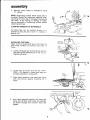
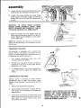
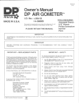
MOUNTING BAND SAW TO WORKBENCH
lf band saw is to be used in a permanent location, it should be f astened securely to a f irm supporting surface such as a workbench.
lf mounting to a',^',orkbench. holes should be
drilled tirougf'sucJorrr"r g surface of the workbench usino dimenstons lustrated.
Each leg shou
I be bolted securely
NOTE: Front two mounting bolts shou ld oe
inserted from the bottom with washer and nut on
rop.
using
5/16 " drameter machlne screws, lockwashers,
and 5/16' hex n uts lnot included). Screl.r
length shou C be l': " plus the thickness of
3.
the bench toc
Locate and r',arK the holes where band saw is
to be mounted.
Drill (4) 3,8 drameter holes through work-
6-5/16"
+
DIA[IETER
(4)HOLES
I
I
I.-
oencn.
4.
3/8"
f
10-r3/16"+l
Place band saw on workbench aligning holes
in feet with holes drilled in workbench.
Insert ali four 5'l6" screws and tiohten.
An alternate method of mounting is to fasten
band saw to a mounting board. The board should
be of suff icient size to avoid tipping of saw while
in use. Any good grade of plywood or chipboard
with a 3/4" minimum thickness is recommended.
(Thinner chipboard can break.)
1. Follow instructions for mounting to workbench, substituting a board 18" x 24" minimum size and using 5/16 inch flat head
screws, lockwashers, and hex nuts (not included). Screw length should be 11/2 " plus
the thickness of the mountino board.
-t
NOTE: For proper stability, holes must be
counter sunk so screw heads are flush with the
bottom surface of supporting board.
24
Tf
I
18"
N4IN
" iIlN
3/8"
//+
D]AN4EIER
6-5i16"
++
l..-to-r3/ro"+l
I
(4)
HOTES
:
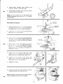
assembly
2.
Securely clamp board
"C" clamps.
to
workbench using
NOTE: Supporting surface where band saw is
mounted should be examined carefully after
mounting to insure that no movement during use
can result. lf any tipping or walking is noted,
secure workbench or supporting surface before
operating band saw.
CLAMPING BANDSAW TO WORKBENCH
The Band Saw can be clamped direcily to a
workbench using two (2) or more "C" clamps on
base of unit.
WORKBENCH
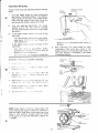
INSTALLING THE TABLE
Apply a coat of automobile wax to the table too
and inside surfaces of trunnion that slide
frame.
1.
on
UPPER
GUIDE
ASSE
I\4
BLY
Loosen the guide bar lock knob and position
the upper guide assembly all of the way up.
Tighten lock knob.
\12
2.
3.
Locate two (2) knobs and two (2\ 17164 x
47164 x 1/16 washers in loose parts bag, and
the table assembly in loose parts.
Place table assembly onto band saw frame
with thd trunnion against mounting rib
in
frame.
TRUNNION
STOTS
4.
Hold table assembly against the frame and
install two (2) taOle lock knobs and washers
as shown through the trunnion slots and
tighten.
-
2
Locate bevel indicator and 10-24x114
pan
cross hd. screw in loose parts bag.
v
o.
Install bevel indicator and screw as shown
using a phillips screwdriver.
NOTE: This unit comes with the Band Saw blade
installed, assembly continues on p. '10, "Tensioning the Blade."
GUIDE BAR
tOCK KNOB
REPLACING THE BLADE
Y
1.
Loosen the guide bar lock knob and position
the upper guide assembly approximately one
inch above the tab e and tighten lock knob.
2.
Loosen the two blade guard mounting screws
and remove the blade ouard.
3.
Loosen the gurde bar lock knob and position
the upper guide assembly approximately two
inches above the table as shown and tighten
the lock knob
4.
Remove table rnsert, truss head screw, washer and wing nut f rom the table (See Assem'
bly, p. 13 - Adjusting the Table"). Replace
these parts after the blade is installed, tensioned and tracked.
5
Loosen the two screws in the front of the
upper blade guide assembly that secure the
blade guides and separate them about'1/8".
6.
Loosen the two screws in the side of the
upper guide assembly and slide guides and
thrust bearing all of the way back.
7.
Tighten all screws.
8.
Loosen the three (3) cover knobs by turning
counterclockwise and remove cover.
NOTE: Replace the bandsaw cover after blade is
properly installed, tensioned and tracked.
UPPER GUIDE
ASSEMBLY
UPPER GU
DE
ASSEI\4 BLY
ry
assembly
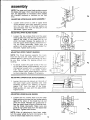
9.
Loosen the two screws that secure the lower
blade guides and separate them about 1/8".
:.
10. Loosen the screw holding the lower blade
guide support and slide support all the way
toward the rear of the saw, and retighten all
screws.
WARNING:
TO AVOID BEING
IENSION WHEEL
SCRAPED
SHOULD BLADE SUDDENLY UNCOIL, WEAR
SAFETY GOGGLES AND CAREFULLY UNCOIL
THE BLADE HOLDING IT AT ARMS LENGTH.
the blade over the wheels with the
teeth pointing downward toward the table as
shown. Make sure the blade is in the center
of the rubber tires.
11. Place
SIOT IN TABLE
DRIVE
V/IEEt
DLER WHEET
NOTE: Your bandsaw can use 1/8 or 114 inch wide
blades, 56-718 inches long. A l14inch blade is included
with this saw.
TENSIONING THE BLADE
The bandsaw is equipped with a self-limiting
tension device. The tension is factory set and
should not need adjustment. The blade must be
installed before tension can be set.
1.
Turn tension adjustment knob until
2.
DO NOT turn knob after contact is made and
resistance if felt. This is the proper tension
setting tor a114" blade.
3.
To release tension turn knob counterclockwise until knob is above the washer and
knob
contacts washer and sleeve.
TENSION SCREW
sleeve.
COMPENSATION FOR WEAR
Tension screw is provided to make minimal
adjustments due to wear. The tension screw
creates a drag between the wheel guide and the
frame.
1.
2.
Remove the blade before adiusting.
Use a phillips screw driver to adjust the ten'
sion screw. Turn clockwise to increase the
WARNING: OVER TENSION AND FAILURE TO
PROPERLY SET BLADE GUIDES AND THRUST
BEARING WILL CAUSE PREMATURE BLADE
BREAKAGE. FOLLOW ADJUSTING BLADE
GUIDE ASSEMBLIES COMPLETELY TO HELP
MAINTAIN NORMAL BLADE LIFE.
drag (tension).
3.
Check tension by lifting up on tension knob. lf the
tension knob will not move the tension screw is too
tight. Adjust by turntng tension screw coun-
terclockwise and recheck,
10
Q
TRACKING THE BLADE
Tension knob must be tightened before tracking
blade.
1.
Turn the upper wheel by hand (clockwise)
and check if the blade remains in the approximate center of the tires. lf the blade moves
away from the center of the tires, while you
are turning the wheels, adjust as follows:
A. Turn the tracking adjustment set screw
slightly with a 1/8" hex wrench. (Turning
B.
t
I
I
T
the set screw moves the tension wheel back
and forth.)
lf the blade moves toward the front of the
band saw:
Turn the tracking adjustment screw clockwise about 114 ol a turn. as thougn you
were tightening it
lf the blade moves tor^,'ard the back of the
band saw:
Turn the tracking adJUstment screw
counterclocki',' se about 114 of a turn as
though yo- .'.e'e toosening it.
Turn the scre,^, just enough to cause the
C.
ALIGNING THE TABI-E SOUARE TO BLADE
LL' -
--.)
>:
Place
a
UIdUU d)
Sl-a': ,- :^e table
u). a:-
in front of
the
Tilt table -: -' -'.-r t.r alinn table 90
A^^.^^r
do1roo nnqrlinnl
anrl
ru , a-=
utrgrucJ
tighten lock r-::s
4.
Adlust zero sio: sel screw using a 1/8" hex
wrench untrl sei screv/ iust touches frame
Check soUareness c'blade to table. Make
readjustments,' -?,essary
I
Set bevel
indtcatc'::
^e up vrtth zero.
I
iIOTE: When table is tilted to a bevel angle, the
lower blade guide support should be lowered to
clear the table. After bevel cutting and returning
table to zero position, always raise the lower
blade guide up to provide maximum support for
ii-re blade.
11
blade to run in the approximate center of
all tires.
After adjusting, turn upper wheel by hand
clockwise a few turns and notice if the
blade remains in the approximate center of
the tires, readjust if necessary, until blade
is tracking Properly.
assembly
NOTE: The upper and lower blade guides support
the blade and keep it from twisting during operation. An adjustment is necessary when blades
are changed, replaced or installed for the first
:.
time.
ADJUSTING UPPER BLADE GUIDE ASSEMBLY
1.
Loosen lower screw on side of upper blade
guide assembly and slide assembly forward
until the front edge of the blade guides are
approximately 1/32" from the GULLET of the
saw blade. Tighten screw.
GULLEI
ADJUSTING UPPER BLADE GUIDES
1.
Loosen the two screws that lock the upper
blade guides and press the two guides evenly
against the sides of the blade but do not
pinch the blade. Release the guides and rotate the upper wheel slightly clockwise moving the blade downward. Make sure one
guide is not further away from the blade than
the other. Tighten both screws.
SAW
BLADE
ADJUSTING UPPER THRUST BEARING
I
NOTE: The thrust bearing supports the blade
from the rear and will rotate when the blade is
pushed against it while you are cutting. As soon
as you stop cutting, the bearing should stop
rotating.
1.
I
I
I
ST
NG
To ad.iust, loosen the upper screw on the side
of the upper blade guide assembly and slide
the bearing forward until it is approximately
1132" trom the back of the blade. Tighten
screw. Rotate upper wheel slightly clockwise
to check clearance. Readiust if necessarv.
v
lo
L:
ADJUSTING LOWER BLADE GUIDE ASSEMBLY
1.
Loosen the screw (as shown) on the side of
the lower blade guide assembly and slide
assembly forward until bearing is approxi'
mately 1132" trom the back of the blade.
Blade guides will align with this adjustment.
Tighten screw.
ADJUSTING LOWER BLADE GUIDES
1.
Loosen the two screws that lock the lower
blade guides and press the two guides evenly
against the sides of the blade but do not
pinch the blade. Release the guides and rotate the upper wheel slightly clockwise moving the blade downward. Make sure one
guide is not further away from the blade than
the other. Tighten both screws.
NOTE: After all adjustments have been made,
turn the upper wheel by hand (clockwise) a few
turns to check blade travel and clearance.
(L
12
DRIVE BELT TENSION
DRIVE BELT
WARNING: TO AVOID INJURY DUE TO ACCI.
DENTAL START, UNPLUG TOOL BEFORE
MAKING ADJUSTMENTS.
The tension on the drive belt has been set at the
factory. lf adjustment is needed, use a 3/16" hex
wrench to loosen upper and lower cap screws.
Pull motor away f rom drive wheel to apply proper
tension to drive belt. Retighten cap screw while
holding motor in place.
ADJUSTING THE TABLE
I
1.
2.
3.
i
4.
5
Replace the blade guard on the upper assembly and tighten screws,
Locate the table insert and place it in the
opening in the table A rgn slot in the insert
with the slot in the table
Locate a 114 -20 x 3 4" truss head screw, a
flat washer. a^c a 1 4 - 20 wing nut in loose
parts. Insert s..e..' nto hole in table top as
illustrated
From the undersrde of the table, install washer and ,^, "_c ^;: onto the truss head screw
and trghte" rrrger tight. This will keep the
table f lat ano rn alignment.
Reo ace 1^e card saw cover.
TRUSS HEAD
SCREW
TAEtE
INSERI
WASHER
WI NGN
---7
U]
^
I
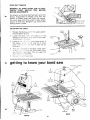
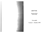
getting to know your band saw
IRACKING ADJUST[/ENT
1
l-
1]JUS-IING'KNOB
5
GUIDE BAR
LOCK KNOB
TABTE
BTADE
TABL
FRONT
E
13
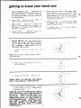
getting to know Your band saw
'1.
5. Guide bar lock
Tension adjusting knob . . . Tightening the
knob (clockwise) will increase the tension on
the blade. Loosening it (counter clockwise)
will decrease the tension. (Tension lock knob
must be released).
2.
Cover knobs . . . Secure cover to frame by
tightening all three (3) cover knobs.
6. Table
Blade Guides . . . Supports the blade and
it from twisting during operation. An
adjustment is necessary when blades are
locks the table in Place,
7. Tilt (bevel) scale... Shows degree table is
changed or replaced.
B.
lock knobs . . . Loosening knobs allows
the table to be tilted and tightening knobs
keeps
4.
knob . . . The upper blade
guide assembly should just clear the workpiece while cutting. Always adjust the upper
guide assembly and lock the guide bar by
tightening the blade guide lock knob before
turning on the band saw
tilted for bevel cutting.
maintains tension
Tension screw
tween upper wheel guide and f rame.
be-
ON-OFF SWITCH. The On-Off Switch has a
locking feature. THIS FEATURE lS INTENDED TO HELP PREVENT UNAUTHORIZED
AND POSSIBLY HAZARDOUS USE
_
BY
CHILDREN AND OTHERS.
1. To turn
machine
on insert key
into
switch.
NOTE: Key is made of yellow plastic; locate in
loose parts bag.
2.
Insert f inger under switch lever and Puil
end of switch out.
3.
To turn machine OFF . . . PUSH lever in.
--
NEVER LEAVE THE MACHINE UNATTENDED
UNT|L IT HAS COME TO A COMPLETE STOP.
4. To lock switch in OFF position
. . . hold
switch lN with one hand . . . REMOVE key
with other hand.
WARNING: FOR YOUR OWN SAFETY, ALWAYS
LOCK THE SWITCH "OFF'' WHEN MACHINE IS
NOT IN USE.. . REMOVE KEY AND KEEP IT IN A
SAFE PLACE. . . ALSO . . . IN THE EVENT OF A
POWER FAILURE (ALL OF YOUR LIGHTS GO
trt
OUT) TURN SWITCH OFF . . . REMOVE THE KEY
AND STORE IT REMOTE FROM BAND SAW.
THIS IYILL PREVENT THE MACHINE FROM
ITARTING UP AGAIN WHEN THE POWER
cotEs
BAGK
oN.
14
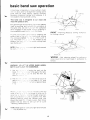
basic band saw operation
A band saw is basically a 'curve cutting" machine lt is also used for straight-line cutting operations such as cross cutting. rpptng, mitering,
beveling, compound cutting. and resawing. lt is
not capable of doing inside cutting.
This band saw is designed to cut wood
SA\/i
KERI:
and
wood like products only.
For general type scroll cutting. follow the pattern
lines by pushing and turning the workpiece at
the same time. Do not try to turn the workpiece
while engaged in the blade ','.rthout pushing it,
PATTEBN tINE
the workpiece could bind o'l'!^,'st the blade.
RIGHT
{^^.,+rl^^
tL/t uuttilrtl
A curve cut iS beSt pe.to.n ed by keeprng the
pattern line in line v,'rt. t^e btade while turning
the workpiece before:^:'al rs of the curve is
cut. The blade si.! r : -1 r the middle of the
pattern line (sav, .r=" s -:e wood cutting band
saw blades are l^ -
I
BLADE
Planning ahead by turning workpiece
d uurvu.
/JCBKPIECE
I
I
NOTE: B ace
for claritv :' :-
a sec and right hand removed
PATTEBN
t
NE
WRONG
Not planning ahead for cutting a
curve could bind or twist blade tf workpiece is
forced.
L/
WARNING: ADJUST THE UPPER GUIDE ASSEMBLYTO JUST CLEAR THE WORKPIECE.
Use bot' -=-:. ',- e feeding the work into the
blade l: :. '- = .', ,". ece f rrmly against the table.
Use ge':: :-:::-': Do not force the work. but
allo\,v tbe : ?.t: :, --.:
.c e that can be cut out is
cf the blade. A 1/4" wtde
r a^1eter of approximately
The sma
;Ja+a'm
UEIE
blade'.',
n ^
=
1-1 2
Be lef
cris a'a - zaa .'. 'en an tntrtcate curve (too
small a r3c uS
'.. z'
.1.nch blade) is to be cut. A
cut s -dr::. --rtrrg through scrap section of workprece ro curve in pattern line, then
relref
carefully backrng biade out. Several reltef cuts
should be made for rntricate curves. then follow
naticrn line as secttonS are cut off of curve
"rel ieving" blade pressure.
NOTE: Blade guard is raised and right hand removed
15
-
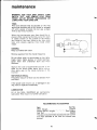
maintenance
WARNING: FOR YOUR OWN SAFETY, TURN
SWITCH "OFF'' AND REMOVE PLUG FROM
POWER OUTLET BEFORE MAINTAINING OR
-
LUBRICATING YOUR BAND SAW.
TIRES
Pitch and sawdust that accumulate on the tires
should be removed with a stiff brush or scraped
off with a piece of wood. Do not use a sharp
knife or any kind of solvent.
When the tires become worn they should be replaced. When replacing the tires, put a thin layer
of rubber cement on the outside of the wheels
and inside of the tires. Allow to dry, then slide
tires onto wheels aligning tires inside wheel
edges.
GENERAL
Keep your Band Saw clean.
Remove sawdust from the inside frequently.
Do not allow pitch to accumulate on the table.
blade insert, blade guides, or thrust bearings.
Clean them with Craftsman Gum and Pitch
Remover.
Apply a thin coat of automobile-type wax to the
table so the wood slides easily while cutting.
Also apply wax to the inside surfaces of the
trun
n
!t
ion.
MOTOR/ELECTRICAL
Frequently vacuum or blow out any sawdust f rom
the motor.
lf the power cord is worn, cut, or damaged in any
way, have it replaced immediately.
LUBRICATION
All of the BALL BEARINGS are
permanently
lubricated. They require no f urther lubrication.
RECOMMEN DED ACCESSORIES
Item
Gauge.....
Blades (56-7/8" length).
Leg Set...
Cal. No.
.....9'24214
Miter
.
See Catalog
922244
The above recommended accessories are current
and were available at the time this manual was
printed.
16
1,
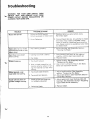
troubleshooting
WARNING: FOR YOUR OWN SAFETY' TURN
SWITCH "OFF'' AND REMOVE PLUG FROM
POWER OUTLET BEFORE READJUSTING OR
ALIGNING YOUR BAND SAW.
Motor will not run.
'1 Defective On-Off switch.
Def
2
ective Power or motor cord.
Blades breakinq.
Motor sounds under
load when not cutting.
Blade will not allow for
general straight cutting.
1. Replace defective parts before using
Band Saw again.
2. Consult Sears Service. Any attempt to repatr
this motor may create a HAZARD unless
t"4otor Defective.
repair is done by a qualif ied service technician. Repair service is available at your nearest Sears Store.
1. Adjust tracking, see Assembly Section,
"Trackino the Blade."
Blade does not run in the 1. Not tracking ProPerlY
approximate center of the
upper wheel.
Band Saw slows down
when cutting.
REMEDY
PROBABLE CAUSE
TROUBLE
1. Cutting too small a radius
1. Stop feeding, and back up the material
slightly, until the band saw speeds up.
2. Dull
2. Replace blade.
blade.
1. Too much tension.
2.
Krnk in blade caused bY cutting too small a radius or turning the material too fast when
c utt ing.
.1.
Too much blade tension.
2. Too much belt tension.
Blade guides and bearings
not properly adjusted.
1. Adjust tension. See Assembly section
"Tensioning The Blade."
2. Use correct cutting technique. See Basic
Band Saw Operation Section.
Adjust blade tension. See Assembly
section "Tensioning The Blade'"
Adjust belt tension. See Assembly Section
"Drive Belt Tension."
1. Adjust upper and lower blade guides and
bearings. See Assembly section "Adjusting
Upper Blade Guide AssemblY."
2. Reolace
Defective blade.
17
blade.
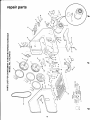
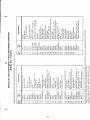
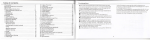
repair parts
fr
i\
.// t'
-ol
-to
N
=
a
o
F,'
\g*t
f-
z
tcq
r \9 -x
l5
o
o
uI
N
@r
E
o
F
o9
r.it,:_g
-$c\
=lr,
+
s-.fQ)A
:-3
;
16 i1\
<-l
zco
v ,- :i ;.-g _
OF
-o
tz
\
\
,<q
-
=d
[5
<=
v, ?l
E
O
E
o
II
F
o
(\l
-\;
-)-;
\c\
ol
o
o
J
'-0
U)
F
t,
U
=
Sn
I
o.
o
z
h
E
\
\ro
o
E
3
o
,dg
=
t
r
ol
7/.-\
(
:
I=
\_-i=
18
Y
N++-)
>'c)
E
d o
tr
R ile
x;r
o s ;R:
S*;
X+:
:4=-.oE Pi
:83
Fd H^b.,
9=
=b
b t=;
=
A q€5.9.q e*Rex u"., I?iI $Fe^
5+
'_ =F
i;;FF,*gsEi#ein+c:i Hi5FEgEr*i$
E!
A; *+ -0-0-
CL
I
o
o
o
a+;
H
aa
.F$#
=EeE;;s.!
z
G
go ;NI
.9
=
a
o
IO
y FS<
F
*H*
;E=+:-e
:EE5;'3#
6T a a#F*EIhtE*t6'H
ornN
=-O
c-Lo
UJ
;=!
N
o
;ergg:€#u535#sFEEF
't
o
F
9P
TF
,v^F
tO
N
o
5
r
a
N
^@
sr
^.^K5
.g
.^P
>:
22
(\cD
N € - O .- N c') $ tO@f-- @O)OF NCD(of'-@O)Or
:a:'. - = = s s I I <t $ $$ LoLoLoLolf)Lotolr)(o(o(o(o
sf tO(olt-@O)O
(o@(o(o(o(of.-
||
|
|
^
:-
o
c
.=
(g
,1
o_
o
a
-=ru
U)
sJ oz
;uJ
tro
LO z
0)
c
=g_>
I
<=
trF I
.ne=
oo-
rrfi
o6
ILH
F:
a= J
o
lt)
F7
Cf-
n_
c0
(r
o
"rJ
t
\J
(n
-
E a? Ie ;
=-
r=
t
=
-o
.a
-o :F
t'44
ra
q)
o
rn
8: S:!'IS5EEF3FF8FUPgFHfi38FS fiSdPJPEFE
.::::3'n663b33333b33883b33 33e;SEEBbB
Ir
Z<rl
-
q)
o
oo{
Q
p-g
trl
=lo
49
-<f
c
'=
o
6
o
o
s
q$!
?
3 FS.o
s,
=cx
X s'idd p
Lc
I
-
O
$--E
(om
ffr[EE;!
+ ? .e:
-;S.&
,X
r-j
=
"j0-t
=
n
3
?o 3b
fseES=*
=f
-F
=z
*
;atrF=i
€0#;Fe
:nC
E;
+YTri^ f'
E: =-.-i ;t t p 6At:dq
*FeP
* ?:EEi+ii
Ei.:+t€;EpF
; $ ;; e gS,i,rF.fi:$s.H5e;;!:e g
=
=
(o
I Rg
3
EE
N
:o
ph
vi
K
6
.^65
6oeq51-sccvpS
soES
F: EU\FNKEHPN=Ns
i83SF$R88SB
q/
q/tLOct X lt*/r-F;*
I
5 ^', X=tX=
'\
=
=
a6-,.l.33336636
3i3;6E53aEaab
9: -NcD$ro(or-coo)P=SP :II>PIRnNRN
Lo LO
19
cD
:<
=T
Lo@.
'"1
;r*€i,j;",==!9
npa
(!.n ()
N-'C)
(g(/)_J
(5(D (D
^,4 a
H- F
b;up
O(!:J
>9 *
(EL
o)
F'rn
!O
(-)>o>
F:;EFtHSFg; 6=
*^-o?-+ay*ro-,,
at 6!gsEF;;:,;
EEt a ai a
ssE
<O****
E
.9=n I
!dL
:v
_=6=
q=
o
3
3 PER
?*-_E-pSEF*
b::septtrppe
-,FFl
l;-;*
^\F ^\
(Drn
L._
RNRR3aS3S33
<tr
o* a
63336386668
(s
=
o-> T
o(/j Y
>,o-:
ffi
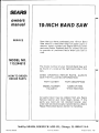
owners
manual
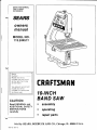
SERVICE
70.'NCH BAND SAW
Now that you have purchased your 10-lnch Band
Saw should a need ever exist for repair parts or
service, simply contact any Sears Service Center
and most Sears, Roebuck and Co. stores. Be sure
to provide all pertinent facts when you call or
visit.
MODEL NO.
113.244513
The model number of your 1O-lnch Band Saw will
be found on a plate at the right-hand side of the
SAW.
HOW TO ORDER
REPAIR PARTS
WHEN ORDERING REPAIR PARTS, ALWAYS
GIVE THE FOLLOWING INFORMATION:
PART NUMBER
PART DESCRIPTION
MODEL NUMBER
NAME OF ITEM
10-lnch Band Saw
113.244513
All parts listed may be ordered from any Sears
Service Center and most Sears stores. lf the
parts you need are not stocked locally, your
order will be electronically transmitted to a Sears
Repair Parts Distribution Center for handling.
Sold by SEARS, ROEBUCK AND CO., Chicago,
Part No. SP5100
Form No. SP5100-1
IL. 60684 U.S.A.
Printed in Taiwan. 4/89
r