1
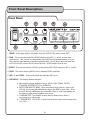
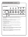
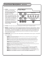
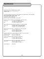
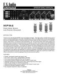
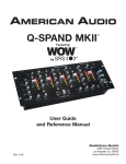
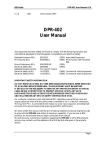
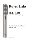
FEATURES:
'
s
m
a
n
u
a
l
• Fully BPM (Beats Per Minute) synchronizable multi-effect signal
processor includes REVERB, ECHO, PAN, FLANGER, TRANSFORM,
FILTER and PITCH BEND.
• Vocal Harmonizer with 2 stages of Higher octaves, 2 stages of
Lower octaves and Double effect.
• Professional Digital Echo can be used simultaneously with Vocal
Harmonizer, Reverb and all other effects.
• Range and Level parameters for each effect.
• 3 XLR or 1/4” mic inputs with invidual volume controls.
• Balanced XLR outputs for optimal fidelity to your sound system and
2 pairs of RCA outputs.
• 3 pairs of RCA inputs for connection of external players or other
components.
• Mic insert allows balanced PHONO connection of external
processor for stereo loop.
• Digital Signal Processor effects are assignable from either music
or mic input.
R
1
L
2
1
2
VSP-M1
3
CAUTION
RISK OF ELECTRIC SHOCK
DO NOT OPEN
r
LA VERNE CALIFORNIA
U S A
WWW.VOCOPRO.COM
ON
OFF
AUDIO OUT
AUDIO IN
MIC 3
MIC 2
MIC 1
MIC INSERT
AC 10V
FOOTSWITCH
VSP-M1
Multi-Effect Digital Signal Processor/Mixer
o
w
n
TRIM OUTPUT
ECHO
R
R
BALANCED
OUTPUT
e
L
L
VSP-M1
Multi-Effect Digital Signal Processor/Mixer
Table of Contents
Listening for a Lifetime ................................... 3
Safety Instructions ......................................... 4
Welcome ...................................................... 5
Front Panel .................................................6-8
Rear Panel ................................................... 9
Getting Connected ....................................... 10
Troubleshooting ........................................... 11
Specifications .............................................. 12
2
Listening For A Lifetime
Selecting fine audio equipment such as the unit you ve just purchased is only the start of
your musical enjoyment. Now it s time to consider how you can maximize the fun and
excitement your equipment offers. VocoPro and the Electronic Industries Association s
Consumer Electronics Group want you to get the most out of your equipment by playing it
at a safe level. One that lets the sound come through loud and clear without annoying
blaring or distortion and, most importantly, without affecting your sensitive hearing.
Sound can be deceiving. Over time your hearing “comfort level” adapts to a higher volume
of sound. So what sounds “normal” can actually be loud and harmful to your hearing. Guard
against this by setting your equipment at a safe level BEFORE your hearing adapts.
To establish a safe level:
• Start your volume control at a low setting.
• Slowly increase the sound until you can hear it comfortably and clearly, and without
distortion.
Once you have established a comfortable sound level:
• Set the dial and leave it there.
• Pay attention to the different levels in various recordings.
Taking a minute to do this now will help to prevent hearing damage or loss in the future.
After all, we want you listening for a lifetime.
Used wisely, your new sound equipment will provide a lifetime of fun and enjoyment. Since
hearing damage from loud noise is often undetectable until it is too late, this manufacturer
and the Electronic Industries Association s Consumer Electronics Group recommend you
avoid prolonged exposure to excessive noise. This list of sound levels is included for your
protection.
Some common decibel ranges:
Level
Example
30
40
50
60
70
80
Quiet library, Soft whispers
Living room, Refrigerator, Bedroom away from traffic
Light traffic, Normal Conversation
Air Conditioner at 20 ft., Sewing machine
Vacuum cleaner, Hair dryer, Noisy Restaurant
Average city traffic, Garbage disposals, Alarm clock at 2 ft.
The following noises can be dangerous under constant exposure:
Level
Example
90
100
120
140
180
Subway, Motorcycle, Truck traffic, Lawn Mower
Garbage truck, Chainsaw, Pneumatics drill
Rock band concert in front of speakers
Gunshot blast, Jet plane
Rocket launching pad
-Information courtesy of the Deafness Research Foundation
3
Safety Instructions
8. Ventilation - The appliance should be situated so its
location does not interfere with its proper ventilation. For
example, the appliance should not be situated on a bed,
sofa, rug, or similar surface that may block the
ventilation slots.
CAUTION
RISK OF SHOCK
CAUTION: To reduce the risk of electric shock,
do not remove cover (or back). No userserviceable parts inside. Only refer servicing to
qualified service personnel.
9. Heat - The appliance should be situated away from
heat sources such as radiators, heat registers,
stoves, or other appliances (including amplifiers)
that produce heat.
10. Power Sources - The appliance should be
connected to a power supply only of the type described
in the operating instructions or as marked on the
appliance.
Explanation of Graphical Symbols
The lightning flash & arrowhead
symbol, within an equilateral triangle,
is intended to alert you to the
presence of danger.
11. Grounding or Polarization – Precautions should be
taken so that the grounding or polarization means of
an appliance is not defeated.
12. Power-Cord Protection – Power-supply cords
should be routed so that they are not likely to be walked
on or pinched by items placed upon or against them,
paying particular attention to cords at plugs,
convenience receptacles, and the point where they exit
from the appliance.
The exclamation point within an
equilateral triangle is intended to alert
you to the presence of important
operating and servicing instructions.
WARNING
13. Cleaning – Unplug this unit from the wall outlet
before cleaning. Do not use liquid cleaners or
aerosol cleaners. Use a damp cloth for cleaning.
To reduce the risk of fire or electric shock, do
not expose this unit to rain or moisture.
14. Power lines – An outdoor antenna should be
located away from power lines.
1. Read Instructions - All the safety and operating
instructions should be read before the appliance is
operated.
15. Nonuse Periods – The power cord of the appliance
should be unplugged from the outlet when left unused
for a long period of time.
2. Retain Instructions - The safety and operating
instructions should be retained for future reference.
16. Object and Liquid Entry – Care should be taken so
that objects do not fall and liquids are not spilled into the
enclosure through openings.
3. Heed Warnings - All warnings on the appliance and in
the operating instructions should be adhered to.
17. Damage Requiring Service – The appliance should
be serviced by qualified service personnel when:
4. Follow Instructions - All operating and use
instructions should be followed.
A.
B.
C.
D.
The power supply cord or plug has been damaged; or
Objects have fallen into the appliance; or
The appliance has been exposed to rain; or
The appliance does not appear to operate normally
or exhibits a marked change in performance; or
E. The appliance has been dropped, or the enclosure
damaged.
5. Attachments - Do not use attachments not
recommended by the product manufacturer as they may
cause hazards.
6. Water and Moisture - Do not use this unit near water.
For example, near a bathtub or in a wet basement and
the like.
18. Servicing – The user should not attempt to service
the appliance beyond that described in the operating
instructions. All other servicing should be referred to
qualified service personnel.
7. Carts and Stands - The appliance should be used
only with a cart or stand that is recommended by the
manufacturer.
Note:
To CATV system installer s (U.S.A.): This reminder is
provided to call the CATV system installer s attention to
Article 820-40 of the NEC that provides guidelines for
proper grounding and, in particular, specifies that the
cable ground shall be connected as close to the point of
cable entry as practical.
7 A. An appliance and cart combination
should be moved with care. Quick stops,
excessive force, and uneven surfaces may
cause an overturn.
4
Welcome….
And Thank you for purchasing the PIANO-5 from VocoPro, your ultimate choice in
Karaoke entertainment! With years of experience in the music entertainment business,
VocoPro is a leading manufacturer of Karaoke equipment, and has been providing
patrons of bars, churches, schools, clubs and individual consumers the opportunity to
sound like a star with full-scale club models, in-home systems and mobile units. All our
products offer solid performance and sound reliability, and to further strengthen our
commitment to customer satisfaction, we have customer service and technical support
professionals ready to assist you with your needs. We have provided some contact
information for you below.
VocoPro
1728 Curtiss Court
La Verne, CA 91750
Toll Free: 800-678-5348
TEL: 909-593-8893
FAX: 909-593-8890
VocoPro Company Email Directory
Customer Service & General Information
[email protected]
Tech Support
[email protected]
Remember Our Website
Be sure to visit the VocoPro website www.vocopro.com for the latest information on new
products, packages and promo s. And while you re there don t forget to check out our
Club VocoPro for Karaoke news and events, chat rooms, club directories and even a
Service directory!
We look forward to hearing you sound like a PRO, with VocoPro, your ultimate choice in
Karaoke entertainment.
FOR YOUR RECORDS
Please record the model number and serial number below, for easy reference, in case of loss or theft. These
numbers are located on the rear panel of the unit. Space is also provided for other relevant information
Model Number
Serial Number
Date of Purchase
Place of Purchase
5
Front Panel Descriptions
Front Panel
2
1
3
4
6
a
b
5
c
d
1. POWER - In the upper postion, this switch turns the VSP-M1 ON, lower position OFF.
2. ECHO - This controls the level of the ECHO effect for only MIC 1, 2 and 3, and not other
input sources. MIC 3 is the only input where the ECHO can be bypassed entirely, so if you
donʼt want an equal amount of the effect applied to MIC 1 and 2 (also 3 while that input has
its ECHO set ON), turn the ECHO control hard left. ECHO output is then at zero.
3. REPEAT - This sets the number of ECHO repeats before MIC ECHO decays for MIC 1, 2 and 3.
4. DELAY - This control sets the DELAY time in between ECHO repetitions.
5. MIC 1, 2, and 3 LEVEL - These knobs adjust the individual MIC levels.
6. LCD DISPLAY - This display window indicates:
a. Which effect is being applied to source; ECHO, PAN, TRANS, FILTER,
FLANGER, REVERB, PITCH or HARMONY
b. BEATS PER MINUTE (BPM). When an external music source is input to the
VSP-M1, the counter will automatically display the BPM for each track. Since
the VSP-M1 has a BPM Auto Synchronization feature, it will automatically cue
the effects to align with the rhythm of the music.
c. X PARAMETER. The RANGE of each effect is shown here in either a
percentage or in miliseconds.
d. Y PARAMETER. The LEVEL of each effect is shown here in a percentage from
0 to 100%.
6
7
c
Front Panel Descriptions
(CONTINUED)
Front Panel
9
11
10
12
13
a
d
7
8
7. DSP EFFECT SELECT - Turn this dial to scroll through ECHO, PAN, TRANS, FILTER,
FLANGER, REVERB, PITCH or HARMONY and push dial to select one of these effects to
apply to an input
8. DSP EFFECT ASSIGN - Push in to apply EFFECT to source music input, and release the
button to the extended position to apply EFFECT to a MIC input.
9. X PARAMETER/ EFFECT RANGE - Used to adjust the time parameter of digital effects in
either a percentage or in miliseconds.
10. Y PARAMETER/ EFFECT LEVEL - Used to adjust the LEVEL parameter of digital effects in
a percentage from 0 to 100%.
11. MUSIC LEVEL - Raises or lowers to overall output of source music from INPUT 1, 2 or 3.
12. INPUT SELECTOR - Correlates to AUDIO IN 1, 2 and 3. Switch this dial to whichever
music source you want to apply effects to.
13. HARMONY - For instant access to the HARMONY effect, press this button and the LED will
change from red to green to indicate that the effect has been switched ON. The default
HARMONY setting is the HIGHER/+100% octave.
14. REVERB - For instant access to the REVERB effect, press this button and the LED will
change from red to green to indicate that the effect has been switched ON. Default X
PARAMETER is 50% and Y PARAMETER is 20%.
7
14
Front Panel Descriptions
15. MEMORY 1 - Use this button if you
want to save your parameters
preferences for one of the effects
With the effect desired selected, set
your X and Y PARAMETER
preferences and hold the
MEMORY 1 button until the red LED
flashes. The preferenes have been
saved. Now when you need to make
a quick selection of this effect with
these parameters, press MEMORY 1
for instant access rather than using
the DSP EFFECT dial When an
effect has been stored, pressing this
button will turn the LED from red to
green, indicating your saved effect
has been recalled.
(CONTINUED)
Front Panel
15
16
17
18
16. EFFECT ON - This button must be pushed, switching the red LED to green, to activate the effects.
17. MEMORY 2 - Use this button if you want to save your parameters preferences for one of the effects. With the
effect desired selected, set your X and Y PARAMETER preferences and hold the MEMORY 2 button until the
red LED flashes. The preferenes have been saved. Now when you need to make a quick selection of this
effect with these parameters, press MEMORY 2 for instant access rather than using the DSP EFFECT dial.
When an effect has been stored, pressing this button will turn the LED from red to green, indicating your
saved effect has been recalled.
18. HARMONY/RANGE - When you press each of these buttons, the LED switches from red to green. These buttons
serve a dual function:
a. HARMONY - The Vocal Harmonizer effect of the VSP-M1 allows you to add harmonizing, octaves or doubling notes to
either a microphone or source music input.
DOUBLE/0 - As an example, if you sing a “C” note (or any other note) into the mic, and have selected the DOUBLE/0
button, a duplicate signal is produced which gives the impression there are two people singing that same note.
LOW/-50% - There are two notes in a major scale that harmonize easily with the root note, the major third and major
fifth. This button will take the C note from our example and match it to the 3rd of its lower octave, E in this case, to
simulates backing bass vocal parts being sung.
LOWER/-100% - Pressing this button adds the major fifth of the lower octave of your root note. In our example of
singing a C note, this would add a G note for very “pop” sounding, or chiming, vibrant bass harmonies.
HIGH/+50% - There are several different higher and lower pitch “octaves,” of every musical note, and pressing this button
will add the next higher octave accompanying the source.
HIGHER/+100% - Press this button to get the next octave, 2 higher than the root note.
b. RANGE - The second function of these buttons is presets or “hot keys” for REVERB and PTICH effects X PARAMETER.
DOUBLE/0 - With the REVERB effect, this button sets the RANGE (X PARAMETER) at 50. With PITCH, RANGE is set 0.
LOW/-50% - With the REVERB effect, this button sets the RANGE (X PARAMETER) at 25. With PITCH, RANGE is set -50%.
LOWER/-100% - With the REVERB effect, this button sets the RANGE (X PARAMETER) at 0. With PITCH, RANGE is -100%.
HIGH/+50% - With the REVERB effect, this button sets the RANGE (X PARAMETER) at 75. With PITCH, RANGE is set at +50%
HIGHER/+100% - With the REVERB and PITCH effects, this button sets the RANGE (X PARAMETER) at 100.
8
Rear Panel Descriptions
Rear Panel
2
1
3
4
5
6
7
8
9
14
12
10
9
1. BALANCED OUTPUT
- Connect
your Left
and Right XLR cables
from
the 11VSP-M1
to13balanced inputs on your
6
a
4
3
2
mixer, amplifier or powered mixer.
2. TRIM OUTPUT - The output level from the VSP-M1 can be adjusted using this control. For the best, clean sound
quality, adjust TRIM until just before the signal begins to distort.
1
5
b
c
d
8
7
3. AUDIO OUT - Connect your Left and Right RCA cables
from these VSP-M1 outputs to a stereo, Home
entertainment system, amplifier, mixer or powered amplifier with RCA in jacks.
4. AUDIO IN - You can connect up to 3 music sources for input selection here, including stereos, disc players,
mixers, etc.
5. MIC INSERT - This jack is used for connection of an outboard processor such as a compressor using only a
single 1/4” TRS (Tip = send, ring = return, Sleeve = signal ground).
6. ECHO ON/OFF - MIC 3 is the only MIC input which allows you the ability to bypass the ECHO effect entirely
rather than simply turning the ECHO level all the way to zero. Press this button in to turn the effect OFF. In the
extended postion, the effect is ON.
7. MIC 1, 2 and 3 INPUTS - These jacks accept either 1/4” microphone cables in the center of the input, or line up
the 3 prongs of an XLR cable with the XLR connection around the center.
8. FOOTSWITCH - Connect any standard footswitch via 1/4” cable here for remote control of the VSP-M1.
9. AC 10V ADAPTOR JACK - Connect included power adaptor here.
9
Getting Connected
Rear Panel Suggested Connections
MICROPHONES (XLR or 1/4” cabled mics)
(1/4” cable)
(XLR L/R cables)
VP600X
FOOTSWITCH
(1/4” TRS cable)
CLG-600
INAUDIBLE
-
GAIN
-10
0
OFF
30
27
24
21
18
15
12
9
+10
-20
-10
(RCA L/R cables)
(BALANCE)
(BALANCE)
(BALANCE)
(BALANCE)
MIC 1
MIC 2
MIC 3
MIC 4
4
+10
-40
2
1
LEVEL
0.1
1
-30
-20
-10
-6
-3
0
RATIO
N.1
AUTO
INAUDIBLE
+6
0
3
4
RELEASE
Sec
-20
+20
OUTPUT
dB
MONO
6
OFF
IN
COMPRESSOR/LIMITER
PROCESS
ENHANCER
GAIN
30
27
24
21
18
15
12
9
6
4
2
1
LEVEL
+
-20
-35
OUT
.05
200
ATTACK
mSec
+3
0.5
MANUAL
8
1.5
+20
THRESHOLD
dB
CH 1
50
2.5
0
-30
THRESHOLD
dB
EXPANDER/GATE
KJ-7800
6
+
-20
-35
-50
-10
-50
0
OFF
+10
STEREO
THRESHOLD
dB
MODE
EXPANDER/GATE
-20
-10
+10
-40
0.1
1
RATIO
M1
-30
-20
-10
0.5
-6
-3
AUTO
+3
+6
3
OUT
.05
200
msec
0
0
MANUAL
8
1.5
+20
THRESHOLD
dB
CH 2
50
2.5
0
-30
4
RELEASE
Sec
-20
+20
OUTPUT
dB
CLG-600
DUAL CHANNEL COMPRESSOR
LIMITER WITH GATE
6
OFF
IN
COMPRESSOR/LIMITER
ENHANCER
DVG-480K
(RCA L/R cables)
CDG-8000
(RCA L/R cables)
Light (DC 12V)
POWER
0
10
-15
+15
-15
+15
-15
+15
-15
+15
5
-15
+15
5
5
+15
5
Echo
10
CUE
0
10
CUE
10
KEY
4
MIC 1
10
CUE
6
KEY
4
KEY
4
CUE
12
12
6
6
0
0
12
12
6
6
0
0
12
RIGHT
6
2
0
0
ECHO
A/V2
5
ON
KEY
4
2
0
10
10
10
10
8
8
8
6
6
6
4
4
4
2
2
2
0
0
0
MASTER L
MASTER R
0
A/V3
10
5
0
0
MIC 3
0
EQUALIZER
ON
6
KEY
4
2
A/V1
0
Graphic Equalizer
CUE
8
6
KEY
4
5
UP
10
2
0
MIC 2
10
8
2
0
0
0
10
CUE
6
KEY
4
2
2
10
8
6
6
0
10
CUE
8
8
DOWN NORMAL
10
8
8
6
0
10
10
+15
-15
+15
Echo
Echo
Echo
0
0
VOCAL
-15
SIGNAL
Bass
Bass
Bass
SIGNAL
0
0
0
0
Bass
SIGNAL
10
Treble
Treble
Treble
5
LEFT
0
10
0
0
0
Treble
-15
0
10
STEREO 3
Gain
Gain
Gain
0
STEREO 2
5
5
5
5
Gain
STEREO 1
1
MIC 4
2
2
ASSIGN
CROSSFADER
10
5
4
ASSIGN
BOOTH
0
10
Digital
Echo
(RCA L/R cables)
KC-3OOPRO
MULTI - DISPLAY
INPUT SELECTOR
DSP KEY CONTROLLER
VOCAL CANCEL
MUSIC VOL
SONIC ENHANCER
KC-300Pro
AUX
AV2
AV1
DSP KEY CONTROLLER
SONIC ENHANCER
DOWN
POWER
RECEIVER
RESET
UP
MULTIPLEX
VOCAL ELIMINATOR
ON
LO
HI
MIN
MAX
The VSP-M1 is versatile as an external component in your already existing system, with amps such as the
VP600X pictured above. You can also connect directly to a power amp that takes RCA L/R inputs. Or, use it to
process any signal from one of these suggested types of components and others with RCA connections. Options
not shown include connecting the VSP-M1 to powered speakers such as PV420s, using the VSP-M1 as a basic
mixer. If you need more Equalization control, or Key Control, try connecting to your VSP-M1 through a KJ-7800
Mixer, and out to your sound system. Another option for Key Control is to connect your player through our KC300PROX and out from the Key Controler to the VSP-M1. See your VocoPro dealer for compatible components!
10
Troubleshooting
Problems
NO OUTPUT
Solutions
Faulty cables from external components should always be
checked first. Try 2 different sets of RCA cables to
eliminate any possibility that cables are defective.
Check other components for malfunction or poor connections.
If other components are compatible, try a BALANCED OUTPUT
(XLR) connection first for optimum sound quality.
Be sure that XLR BALANCED OUTPUT cables are firmly seated in
their connection jack. They should be immobile from being easily
pulled out.
Rotate all RCA cables slightly at their connection points.
Check MUSIC Level.
Check INPUT SELECTOR to make sure your INPUT source
# matches.
Check DSP EFFECT ASSIGN to see that it matches your
MIC or MUSIC input type.
If microphones are in use, check each microphone for
malfunction and poor connection
Check the proper MIC Level control which matches your
MIC INPUT #.
EFFECT LEVEL and RANGE can also affect OUTPUT level.
Adjust accordingly for best output.
NO ECHO
Check ECHO Level on front panel.
If your microphone is connected to MIC INPUT 3, this is the only
MIC in which ECHO can be completely bypassed using the ECHO
ON/OFF switch for that mic from the back panel.
REPEAT and DELAY controls should also be adjusted to get full
ECHO effect.
DISTORTION
When using BALANCED OUTPUT (XLR Left and Right), it is
important to adjust the trim output to a point which delivers the
cleanest Signal-to-Noise ratio. The output should have enough
gain to be audible with a clear signal.
Check microphone levels to moderate mic input to a more
suitable level.
External connections often offer Level, Volume, Gain, Equalization,
Master and channel faders to set the overall output to your sound
system. The key is finding a balance between all of these factors
to produce the cleanest tone.
Try different effects to reach desired tones.
11
Specifications
Power Source: AC 10V, 1000mA +/-10%, 10 Watts
Dimensions: 482 (W) x 43.7 (H) x 160 (D) mm
Weight: 2.6 Kgs
Input/output impedance & sensitivity (FX OFF, Maximum Gain, 0dBV output, Load=100K OHM)
Audio of AV: 20K OHM /-10dBV (316mV): +/-2dB
Mic: 2K OHM /-50dBV (3.16mV): +/-2dB
Unbalanced output: 1K OHM / 0dB
Balanced output: 600 OHM / 4dBm (1.23V) +/-2dB
Frequency response (Maximum Gain, 0dBV output, Load=100K OHM)
Audio of AV:
20 - 20K Hz +0/-1dB (FX OFF)
20 - 20K Hz +0/-1.5dB (FX ON,DRY)
Mic:
20 - 20K Hz +0/-3dB (FX OFF)
THD + N (Maximum Gain, 0dB output, w/20KHz LPF, Load=100K OHM)
Audio of AV:
Less than 0.008% at 20-20KHz (FX OFF)
Less than 0.03% at 1KHz (FX ON,DRY)
Mic:
Less than 0.04% at 20-20KHz (FX OFF)
Maximum input (Output THD=1%, Maximum Gain, Load=100K OHM)
Audio of AV:
More than +4dBV (FX OFF)
More than +3dBV (FX ON,DRY)
Mic:
More than -39dBV (FX OFF)
Maximum output (EQ flat, maximum gain, Fx off, THD=1%, load=100K OHM)
Unbalanced output:
More than +12dBV (4.0V)
Balanced output:
More than +14dBm (4.0V)
Output noise (Maximum Gain, w/20KHz LPF, A-Weighted)
Audio of AV:
Less than -95dBV (FX OFF)
Less than -82dBV (FX ON,DRY)
L/R Crosstalk (Maximum Gain, 1KHz, 0dBV output, w/20KHz LPF)
Audio of AV:
More than 75dB (FX OFF)
More than 65dB (FX ON,DRY)
Channel Balance:
Within 3dB
12
Vocopro 2004
V 1.0
WWW.VOCOPRO.COM
C