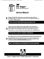
1
Check the 3MTM Bair HuggerTM therapy website to ensure you have the most recent version of this document.
www.bairhugger.com reorder #202430A
3
Bair Hugger™
Model 505 Warming Unit
Service Manual
Warning: Electrical Shock Hazard. There are electrically live parts within the
warming unit when it is connected to a power source, even when the switches are
in the OFF or STANDBY position.
Please forward to Biomedical Engineering Department
UNITÉ DE GESTION DE TEMPÉRATURE BAIR HUGGER MODÈLE 505 SERVICE MANUEL
Mise en garde : Risque d’électrocution. Certaines pièces sont électriquement chargées
dans les appareils de réchauffement, lorsque ceux-ci sont connectés à une source
d’alimentation et ce, même si l’appareil est en position OFF (arrêt) ou STANDBY (attente).
A transmettre au Service d’ingénierie biomédicale
BAIR HUGGER MODELL 505 TEMPERATURMANAGEMENTGERÄT SERVICE GEBRAUCHSANLEITUNG
Vorsicht: Gefährliche elektrische Spannung. In einem an das Stromnetz angeschlossenen
Wärmegerät stehen bestimmte elektrische Komponenten auch dann unter Strom, wenn
der Schalter auf AUS oder BEREITSCHAFTSMODUS geschaltet ist.
Bitte an die Abteilung für biomedizinische Technik weiterleiten
To t a l Te m p e r a t u r e M a n a g e m e n t™ S y s t e m
Check the 3MTM Bair HuggerTM therapy website to ensure you have the most recent version of this document.
www.bairhugger.com reorder #202430A
Check the 3MTM Bair HuggerTM therapy website to ensure you have the most recent version of this document.
3
Bair Hugger
Model 505 Warming Unit
Service Manual
English 1
Français 29
Deutsch 59
www.bairhugger.com reorder #202430A
Check the 3MTM Bair HuggerTM therapy website to ensure you have the most recent version of this document.
Table of Contents
Introduction������������������������������������������������������������������������������������������������������������������������������ 1
Description of the Total Temperature Management™ System���������������������������������������������������� 1
Indications���������������������������������������������������������������������������������������������������������������������������������� 1
Contraindications������������������������������������������������������������������������������������������������������������������������ 1
Definition of Symbols �������������������������������������������������������������������������������������������������������������� 2
Explanation of Signal Word Consequences �������������������������������������������������������������������������������� 3
WARNINGS �������������������������������������������������������������������������������������������������������������������������������� 3
CAUTIONS���������������������������������������������������������������������������������������������������������������������������������� 4
NOTICES������������������������������������������������������������������������������������������������������������������������������������ 5
Read Before Servicing Equipment���������������������������������������������������������������������������������������������� 6
Service Procedures������������������������������������������������������������������������������������������������������������������ 7
Cabinet Cleaning������������������������������������������������������������������������������������������������������������������������ 7
Hose Replacement���������������������������������������������������������������������������������������������������������������������� 7
Power Fuse Replacement ���������������������������������������������������������������������������������������������������������� 8
Control Board Fuse Replacement ���������������������������������������������������������������������������������������������� 9
Air Filter Replacement �������������������������������������������������������������������������������������������������������������11
Over Heat Alarm Testing�����������������������������������������������������������������������������������������������������������12
Over Heat Alarm Thermostat Adjustment���������������������������������������������������������������������������������� 15
Normal Operating Temperature Testing�������������������������������������������������������������������������������������17
Normal Operating Temperature Adjustment������������������������������������������������������������������������������ 19
Troubleshooting���������������������������������������������������������������������������������������������������������������������� 21
Call Technical Support for Replacement Parts�������������������������������������������������������������������������� 21
Technical Support and Customer Service���������������������������������������������������������������������������� 22
When You Call for Technical Support���������������������������������������������������������������������������������������� 22
In-Warranty Repair and Exchange USA������������������������������������������������������������������������������������ 22
Worldwide�������������������������������������������������������������������������������������������������������������������������������� 22
Returning Units for Service������������������������������������������������������������������������������������������������������ 23
Exploded Drawing������������������������������������������������������������������������������������������������������������������ 26
www.bairhugger.com reorder #202430A
Check the 3MTM Bair HuggerTM therapy website to ensure you have the most recent version of this document.
www.bairhugger.com reorder #202430A
Introduction
Description of the Total Temperature Management™ System
The 3MTM Bair HuggerTM brand Total Temperature
Management system consists of a Bair Hugger forced-air
temperature management unit (with available rolling stand and
sheet clip) and disposable components, including Bair Hugger
forced-air blankets, 3MTM Bair PawsTM patient warming gowns,
and the 3MTM 241TM blood/fluid warming set. You can use the
Model 505 temperature management unit in all clinical settings
including the operating room to provide patient temperature
management.
The Bair Hugger warming unit is attached to the blanket or
gown by means of a flexible hose. Warm air is generated in the
unit and flows through the hose and into the blanket or gown.
Depending on the model, the blanket or gown is placed either
around, over, or underneath the patient. Small perforations on
the blanket or gown allow the warm air to be dispersed over the
patient. For fluid warming applications, the Model 241 blood/
fluid warming set is inserted in the warming unit hose. When the
unit is turned ON and a temperature setting is selected, warm air
flows over the Model 241 tubing and warmed fluid exits from
the distal end of the tubing. For additional information on Bair
Hugger blankets, Bair Paws gowns, the 241 warming set, or other
accessories visit us online at bairhugger.com or bairpaws.com.
This manual describes how to service the Model 505 warming
unit, and includes maintenance instructions and specifications.
For information about using Bair Hugger blankets, the 241
blood/fluid warming set, or Bair Paws gowns with Bair Hugger
units, refer to the “Instructions for Use” included with each of
these disposable components.
Indications
The Bair Hugger temperature management system is intended
to prevent and treat hypothermia. In addition, the temperature
management system can be used to provide patient thermal
comfort when conditions exist that may cause patients to
become too warm or too cold. The temperature management
system can be used with adult and pediatric patients.
Contraindications
Do not apply heat to lower extremities during aortic
cross-clamping. Thermal injury may occur if heat is applied to
ischemic limbs.
English 202430A
1
Check the 3MTM Bair HuggerTM therapy website to ensure you have the most recent version of this document.
www.bairhugger.com reorder #202430A
Definition of Symbols
ON/STANDBY
ON (used on isolation switch)
OFF (used on isolation switch)
ON/OFF push button switch
Temperature Control
An equipotentiality plug (grounded) conductor other than a protective earth conductor or a neutral conductor, providing a direct connection between electrical equipment and the potential equalization busbar of the electrical installation.
Please consult IEC 60601-1; 2005 for requirements.
Fuse
CAUTION
Dangerous Voltage
Type BF Equipment (patient applied)
VAC V
Voltage, Alternating Current (AC)
This system is subject to European WEEE Directive 2002/96/EC.
This product contains electrical and electronic components and must not be disposed of using standard refuse collection. Please consult local directives for disposal of electrical and electronic equipment.
Protective earth ground
No free hosing
Date of manufacture
Manufacturer
2
Consult instructions for use
Follow instructions for use
Bair Hugger Model 505 Service Manual
Check the 3MTM Bair HuggerTM therapy website to ensure you have the most recent version of this document.
www.bairhugger.com reorder #202430A
Recycle to avoid environmental contamination. This product contains recyclable parts. For information on recycling, please contact your nearest 3M Service Center for advice.
Keep dry
Temperature limit
Explanation of Signal Word Consequences
warning:
caution:
notice:
Indicates a hazardous situation which, if not avoided, could
result in death or serious injury.
Indicates a hazardous situation which, if not avoided, could
result in minor or moderate injury.
Indicates a situation which, if not avoided, could result in
property damage only.
WARNINGS
1. Do not leave patients with poor perfusion unmonitored
during prolonged warming therapy sessions. Thermal injury
may result.
2. The Bair Hugger temperature management unit has been
designed to operate safely ONLY with 3M Patient Warming
disposable components. Use with other products may cause
thermal injury. (To the full extent permitted by law, the
manufacturer and/or importer declines all responsibility
for thermal injury resulting from the unit being used in
conjunction with non-3M Patient Warming products.)
3.
Do not warm patients with the temperature
management unit hose alone. Thermal injury may
result. Always connect the hose to a Bair Hugger
blanket or Bair Paws gown before providing therapy.
4. Do not place the non-perforated side of the blanket on
the patient. Thermal injury may result. Always place the
perforated side (the side with small holes) towards the
patient.
5. Do not continue temperature management therapy if the
Over-temp indicator light illuminates and the alarm sounds.
Thermal injury may result. Unplug the unit, and contact a
qualified service technician.
English 202430A
3
Check the 3MTM Bair HuggerTM therapy website to ensure you have the most recent version of this document.
www.bairhugger.com reorder #202430A
6. Do not continue 241 blood/fluid warming therapy if the Over-temp indicator
light illuminates and the alarm sounds. Immediately stop fluid flow, and discard
the blood/fluid warming set. Unplug the temperature management unit, and
contact a qualified service technician.
7. Do not use a forced-air warming device over transdermal medication. Increased
drug delivery and patient injury or death may occur.
8. Do not allow the patient to lie on the warming unit hose or allow the hose to
directly contact the patient’s skin during patient warming; thermal injury may
result.
9. Reusable blankets made from woven fabric, or blankets without discrete, visible
holes, can cause the safety system of this unit to fail, which may result in serious
thermal injury. This warming unit has been designed to operate safely ONLY
with Bair Hugger blankets and Bair Paws gowns.
10. Do not connect a Bair Hugger blanket, 241 blood/fluid warmer, or Bair Paws
gown to the warming unit if it has been cut or damaged; thermal injury may
result.
11. Do not use a Bair Hugger blanket to transfer or move the patient; injury may
result.To reduce the risks associated with hazardous voltage and fire:
• keep power cord visible and accessible at all times. The plug on the power
cord serves as the disconnect device. The wall socket outlet shall be as close as
practical and shall be easily accessible.
• use only the power cord specified for this product and certified for the
country of use.
• do not allow the power cord to get wet.
• do not use the warming unit when it appears the warming unit, power cord
or any component is damaged. Contact 3M Patient Warming Technical
Support at 1-800-733-7775.
• this equipment must only be connected to a supply mains with protective
earth.
12. To reduce the risks associated with exposure to biohazards always perform the
decontamination procedure prior to returning the warmer for service and prior to
disposal.
13. Do not retain the patient using a warming blanket alone, as injury may result.
Use a draw, sheet safety strap, or other means to retain the patient.
14. Do not modify this equipment without authorization of the manufacturer.
15. To ground the Bair Hugger warming unit, only connect to receptacles marked
“Hospital Only,” “Hospital Grade,” or a reliable grounded outlet.
CAUTIONS
1. Except for specific blanket models, Bair Hugger blankets are not sterile and are all
intended for single patient use ONLY. Placing a sheet between the Bair Hugger
blanket and the patient does not prevent contamination of this product.
2. Monitor the temperature and cutaneous response of patients who are incapable of
reacting, communicating and/or who are without a sense of feeling every 10-20
4
Bair Hugger Model 505 Service Manual
Check the 3MTM Bair HuggerTM therapy website to ensure you have the most recent version of this document.
www.bairhugger.com reorder #202430A
minutes or according to institutional protocol. Monitor
the patient’s vital signs regularly. Adjust air temperature or
discontinue therapy when the therapeutic goal is reached or
if vital sign instability occurs. Notify physician of vital sign
instability immediately.
3. Do not leave pediatric patients unattended during therapy.
4. Do not initiate temperature management therapy unless
the temperature management unit is free from mechanical
damage and is safely placed on a hard surface or securely
mounted. Otherwise, injury may result.
5. To prevent tipping, clamp the Model 775 temperature
management unit to an IV pole at a height that provides
stability. We recommend clamping the unit no higher than
44” (112 cm) on an IV pole with a minimum 28” (71 cm)
diameter wheelbase. Failure to do so may result in IV pole
tipping, catheter site trauma, and patient injury.
6. Electrical shock hazard. Do not disassemble the temperature
management unit unless you are a qualified service
technician. There are electrically live parts within the unit
when it is connected to a power source, even when the unit
is in Standby mode.
7. To reduce the risks associated with environmental
contamination follow applicable regulations when disposing
of this device or any of its electronic components.
NOTICES
1. The Bair Hugger temperature management unit meets
medical electronic interference requirements. If radio
frequency interference with other equipment should occur,
connect the unit to a different power source.
2. Federal law (USA) restricts this device to sale by or on the
order of a licensed healthcare professional.
3. To avoid Bair Hugger warming unit damage:
• do not immerse the Bair Hugger warming unit or
warming unit parts or accessories in any liquid or
subject them to any sterilization process.
• do not use solvents such as acetone or thinner to clean
the warming unit; avoid abrasive cleaners.
• clean warming unit exterior with soft cloth using plain
water or a mild, all-purpose or nonabrasive cleaner.
English 202430A
5
Check the 3MTM Bair HuggerTM therapy website to ensure you have the most recent version of this document.
www.bairhugger.com reorder #202430A
Read Before Servicing Equipment
The repair, calibration, and servicing of the warming unit
requires the skill of a qualified medical equipment service
technician who is familiar with good practice for medical
device repair. If service is designated as not requiring
manufacturer’s attention, the technical information is provided
in this service manual or will be provided, on request, by 3M
Patient Warming
Refer to Service Manual
Perform all repairs and maintenance in accordance with the
instructions in this service manual.
Safety Inspection
Perform a safety inspection after making repairs to the
Bair Hugger warming unit and before returning the warming
unit to service. A safety inspection should include a test of the
operating temperatures (described in this service manual), the
Over Heat alarm system, as well as a leakage current test.
Proper Use and Maintenance
3M Patient Warming assumes no responsibility for the
reliability, performance, or safety of the equipment if:
• Modifications or repairs are performed by non-authorized
personnel.
• The equipment is used in a manner other than that described
in the Operator’s or Service Manuals.
• The equipment is installed in an environment that does not
meet the relevant grounding requirements.
6
Bair Hugger Model 505 Service Manual
Check the 3MTM Bair HuggerTM therapy website to ensure you have the most recent version of this document.
www.bairhugger.com reorder #202430A
Service Procedures
Cabinet Cleaning
Tools/Equipment
Soft cloth, lightly dampened with water and mild detergent.
Method
1. Disconnect the warming unit from the power source.
2. Wipe the exterior of the warming unit clean.
CAUTION: Do not use a dripping wet cloth when cleaning the
warming unit. Moisture may seep into the electrical contacts
and damage the components. Also, do not use alcohol or other
solvents to clean the cabinet. Solvents may damage the labels and
other plastic parts.
Hose Replacement
Method
1. Press the tab on the blower outlet to release the existing
hose.
2. Attach the replacement hose by inserting the flange end at
a 45° angle in the grooved blower outlet, then snap the hose
into place. (See Figure 1.)
Figure 1. Attaching the
Replacement Hose
Press this
tab to
release
hose
English 202430A
Insert flange into
groove and snap into
place
7
Check the 3MTM Bair HuggerTM therapy website to ensure you have the most recent version of this document.
www.bairhugger.com reorder #202430A
Power Fuse Replacement
The power fuses are located in the power entry module. A
spare fuse is located in the fuse carrier (see Figure 2).
Tools/Equipment
Phillips-head screwdriver
Small slotted screwdriver
Method
1. Disconnect the warming unit from the power source.
2. Remove the 2 Phillips-head screws that secure the cord
retainer. Remove the power cord.
3. Locate the fuse carrier in the center of the power entry
module (see Figure 2).
4. Use the small screwdriver to remove the fuse carrier from
the power entry module.
5. Remove the blown fuse(s) from the fuse carrier.
6. Place the new fuse(s) (as marked) into the fuse carrier.
CAUTION: Replace only with the fuse capacity and type that is
indicated on the adjacent label.
7. Replace the fuse carrier into the power entry module.
8. Reattach the power cord.
9. Replace the 2 Phillips-head screws to reattach the cord
retainer.
10. Reconnect the warming unit to the power source.
11. Record the maintenance action taken and the hours of
operation (read from the hour meter) in the Maintenance
Log section.
Figure 2. Location
of Power Fuse
Power entry
module (see
detail)
8
Bair Hugger Model 505 Service Manual
Check the 3MTM Bair HuggerTM therapy website to ensure you have the most recent version of this document.
www.bairhugger.com reorder #202430A
Control Board Fuse Replacement
Control board fuses are located on the control board. (See
Figure 3.) The internal fuses on the Model 505 are for control
board functions only.
The power fuses are located in the power entry module.
Instructions for power fuse replacement can be found in the
Power Fuse Replacement section.
Tools/Equipment
Phillips-head screwdriver
Method
1. Disconnect the warming unit from the power source.
2. Turn the Model 505 unit over, so that the bottom panel is
facing up.
3. Using the Phillips-head screwdriver, remove the screw from
each of the 2 front feet (bumpers) and remove the feet.
4. Remove the Phillips-head screw from the center of the
upper rear panel.
5. Remove the 2 Phillips-head screws located under the bed
hooks on the upper rear panel. Turn the unit right side up.
6. Lift the top cover and unhook the front of the top cover
from the retainer bracket inside. The control panel is
located on the underside of the top cover. See Figure 3 for
location of the fuse.
7. Remove the fuse and replace with the new one.
CAUTION: Replace only with the fuse capacity and type that is
indicated on the adjacent label.
English 202430A
9
Check the 3MTM Bair HuggerTM therapy website to ensure you have the most recent version of this document.
www.bairhugger.com reorder #202430A
Control Board Fuse Replacement
8. Hook the retainer bracket onto the front of the top cover.
9. Place the top cover back into position. Replace all screws.
NOTE: It may be necessary to remove the air filter to correctly
position the lower portion of the retainer bracket inside the
unit.
10. Reconnect the warming unit to the power source.
11. Record the maintenance action taken and the hours of
operation (read from the hour meter) in the Maintenance
Log section.
Figure 3. Location of
Control Board Fuse
Flip the top cover to access the
control board
Phillips-head screws
Control board
fuse
Retainer bracket
Retainer bracket
hooks into top cover
and is secured by
screws through two
front “feet”
10
Bair Hugger Model 505 Service Manual
Check the 3MTM Bair HuggerTM therapy website to ensure you have the most recent version of this document.
www.bairhugger.com reorder #202430A
Air Filter Replacement
The air filter is mounted in the bottom of the warming unit
(See Figure 4).
Tools/Equipment
Phillips-head screwdriver
Service Frequency
Every 12 months or 500 hours of use.
Method
1. Disconnect the warming unit from the power source.
2. Remove the M6 x 25 pan-head screw on the bottom of the
unit. The filter should slide out easily.
3. Record the hour meter reading and date on the new air
filter label. The hour meter is located in the lower left
corner of the top warning label (see Figure 4).
4. Slide the new filter into the base of the unit.
5. Replace the M6 x 25 pan-head screw on the bottom of the
unit.
6. Reconnect the warming unit to the power source.
7. Record the hour meter reading and maintenance action
taken in the Maintenance Log section.
Figure 4. Location
of Air Filter and
Hour Meter
Hour meter
Air filter
English 202430A
11
Check the 3MTM Bair HuggerTM therapy website to ensure you have the most recent version of this document.
www.bairhugger.com reorder #202430A
Over Heat Alarm Testing
WARNING: Perform all testing and adjustments of warming unit
temperature with Temperature Test Unit Model 22110. 3M
Patient Warming assumes no responsibility for the reliability,
safety, or performance of the Bair Hugger system if warming unit
temperature testing or adjustments are made in any other manner
than that described here. Improper measurement or adjustment of
the warming unit’s over heat alarm setting could result in patient
exposure to temperatures outside of the indicated range, and may
lead to patient injury.
NOTE: The Temperature Test Unit Model 22110 is designed to
simulate the operating characteristics of Bair Hugger blankets and
Bair Paws gowns when used with Bair Hugger warming units; use
of the temperature test device with any other warming system may
result in imprecise readings.
The Temperature Test Unit Model 22110 temperature readings are
taken from a calibrated temperature meter.
Service Frequency
12-month intervals or 500 hours of use
Tools/Equipment
Phillips-head screwdriver
• Use a calibrated temperature meter that can accept a male
subminiature connector and read a K style thermocouple
(e.g., a Fluke Model 52 K/J Thermometer).
• If the connector does not fit your meter, you can remove
the provided connector and attach a connector that fits your
meter.
12
Bair Hugger Model 505 Service Manual
Check the 3MTM Bair HuggerTM therapy website to ensure you have the most recent version of this document.
www.bairhugger.com reorder #202430A
Over Heat Alarm Testing
Method
The Over Heat alarm test panel is located on the back panel of
the Model 505 (see Figure 5).
1. Insert the open hose end from the warming unit in the port
on the Temperature Test Unit (see Figure 6).
NOTE: Do not block the rear air vents on the test device.
Figure 5. Location of Over Heat
Alarm Test Panel
Figure 6. Temperature Test Unit Model 22110
Hose
Port
Test
panel
2. Connect the warming unit to the power source and press
the system ON button.
NOTE: The temperature setting will not affect the Over Heat
test.
3. Using the Phillips-head screwdriver, remove the screw on
the alarm test panel. The unit will go into an over heat
condition when the test panel is loose.
4. When the over heat alarm activates both visually and
audibly, note the maximum temperature achieved. Let the
alarm operate for at least 1 minute or until the temperature
test kit read-out is approximately 38°C (100°F), then press
Standby; the alarm should also turn off. The alarm and
manual reset constitutes one cycle. Pressing ON again will
restart the overheat cycle.
NOTE: If the alarm does not turn off, allow the unit to alarm for
1 more minute before turning the warming unit to STANDBY,
then ON again.
English 202430A
13
Check the 3MTM Bair HuggerTM therapy website to ensure you have the most recent version of this document.
www.bairhugger.com reorder #202430A
Over Heat Alarm Testing
5. Allow the warming unit to cycle 2 times more after the first
satisfactory reading. When the alarm activates, note the
alarm temperature read-out from the test kit. See Table 1
for specified limits.
NOTE: The first over heat cycle temperature may be slightly
higher when started from a cold start.
6. If the results of the test did not meet specified limits,
adjust the over heat thermostat. See the Over Heat Alarm
Thermostat Adjustment section.
7. If the results of the test did meet specified limits, turn the
warming unit to STANDBY, and disconnect the warming
unit from the power source.
8. Remove the hose end from the port on the Temperature
Test Unit.
9. Retighten the screw on the over heat alarm test panel.
10. Record the maintenance action taken and hours of
operation (read from the hour meter) in the Maintenance
Log section.
Table 1. Over Heat Specification
High Temperature Thermostat Model 505
The thermostat interrupts power to the heater and activates
the alarm at a preset high temperature of 53° ± 3°C
(127.4° ± 5.4°F) or less at the end of the hose, as determined
by the Temperature Test Unit Model 22110.
14
Bair Hugger Model 505 Service Manual
Check the 3MTM Bair HuggerTM therapy website to ensure you have the most recent version of this document.
www.bairhugger.com reorder #202430A
Over Heat Alarm Thermostat Adjustment
WARNING: Improper adjustment of the warming unit’s over heat
alarm setpoint could result in patient exposure to temperatures
outside of the indicated range, and may lead to patient injury.
• Closely follow instructions for thermostat adjustment.
• Dangerous voltages are present at the terminals of the
thermostat.
• Always use a Temperature Test Unit Model 22110 to verify
output temperatures.
• The Temperature Test Unit Model 22110 does not need to be
calibrated. The meter it is connected to must be calibrated.
Follow the calibration instructions in the meter service manual or
follow standard facility calibration schedules.
• When in doubt, contact 3M Patient Warming Technical Support
for assistance in temperature adjustment.
Tools/Equipment
• Temperature Test Kit Model 22110
• Small slotted screwdriver
• Phillips-head screwdriver
Method
1. Insert the open hose end from the warming unit in the port
on the temperature test device.
NOTE: Do not block the rear air vents on the test device.
2. Connect the warming unit to the power source and turn the
warming unit power ON.
NOTE: The temperature setting will not affect the over heat
adjustment.
3. Using the Phillips-head screwdriver, remove the screw on
the alarm test panel. Lift and remove the panel.
English 202430A
15
Check the 3MTM Bair HuggerTM therapy website to ensure you have the most recent version of this document.
www.bairhugger.com reorder #202430A
Over Heat Alarm Thermostat Adjustment
4. Locate the over heat adjustment thermostat (see Figure 7).
NOTE: Adjustment of the over heat alarm thermostat
is most easily done while the temperature read-out is
climbing.
5. Use a small slotted screwdriver to adjust the thermostat.
• If the tested alarm temperature was below the
specified limits, turn the screwdriver CLOCKWISE to
increase the alarm temperature.
• If the tested alarm temperature was above
specified limits, turn the screwdriver
COUNTERCLOCKWISE to lower the alarm
temperature.
6. Fine-tune the adjustment until the warming unit alarms at
the specified temperature.
7. Manually turn the warming unit to STANDBY, then
ON again. This manual reset constitutes one cycle.
8. Retest the alarm temperature to verify correct adjustment at
least 2 times. Allow the warming unit to cycle before each
test.
9. When the warming unit alarm setting is within the
specified limit, turn the warming unit to STANDBY and
disconnect it from the power source.
10. Remove the hose end from the temperature test device.
11. Replace the over heat alarm test panel. Resecure the screw.
12. Record the maintenance action taken and the hours of
operation (read from the hour meter) in the Maintenance
Log section.
Figure 7. Location of Over
Heat Alarm Thermostat
Over heat alarm
thermostat access
(detail)
16
Bair Hugger Model 505 Service Manual
Check the 3MTM Bair HuggerTM therapy website to ensure you have the most recent version of this document.
www.bairhugger.com reorder #202430A
Normal Operating Temperature Testing
WARNING: Perform all testing and adjustments of warming
unit temperature a Temperature Test Unit Model 22110.
Arizant Healthcare Inc. assumes no responsibility for the reliability,
safety, or performance of the Bair Hugger system if warming unit
temperature testing or adjustments are made in any other manner
than that described here. Improper measurement or adjustment of
the warming unit’s normal operating temperature could result in
patient exposure to temperatures outside of the indicated range,
and may lead to patient injury.
Service Frequency
6-month intervals, or 500 hours of use
Tools/Equipment
Temperature Test Unit Model 22110
Method
1. Insert the open hose end from the warming unit in the port
on the temperature test device (see Figure 6).
NOTE: Do not block the rear air vents on the test device.
2. Turn the warming unit power ON and select the
HIGH temperature setting. Always begin testing at the
HIGH setting.
3. Note the ambient room temperature.
4. After approximately 5 minutes of operation, note the
temperature read-out. Use Figure 8 to correlate ambient
temperature to the warming unit’s operating temperature.
Figure 8. Room Temperature vs. High
Temperature Output
At HIGH, Nominal Temperature on
Test Kit (°C)
At HIGH, Nominal Temperature on Test
Kit (°F)
Warming unit temperature setting should be on HIGH when
conducting this test
Ambient Room Temperature (°C)
English 202430A
1
Ambient Room Temperature (°F)
17
Check the 3MTM Bair HuggerTM therapy website to ensure you have the most recent version of this document.
www.bairhugger.com reorder #202430A
Normal Operating Temperature Testing
5. After correcting for ambient temperature, the tested normal
operating temperature should meet the limits specified in
Table 2.
6. If the HIGH temperature setting is not within specified
limits, adjust the normal operating temperature. See the
Normal Operating Temperature Adjustment section.
7. If the HIGH temperature setting is within specified
limits, verify the MED and then LOW settings against
specified limits (allow the warming unit to operate at each
temperature setting for about 3 to 5 minutes
before test).
8. Turn the warming unit to STANDBY. Remove the hose
end from the port on the temperature test device.
9. Record the maintenance action taken and the hours of
operation (read from the hour meter) in the Maintenance
Log section.
Table 2. Operating Temperatures Model 505
(Operating temperature = Average temperature at the end of the hose.)
HIGH: MED: LOW: 43° ± 3°C (109.4° ± 5.4°F)
38° ± 3°C (100.4° ± 5.4°F)
32° ± 3°C (89.6° ± 5.4°F)
Note: Air temperature reaching the patient is approximately 2°C lower than
the listed temperatures.
18
Bair Hugger Model 505 Service Manual
Check the 3MTM Bair HuggerTM therapy website to ensure you have the most recent version of this document.
www.bairhugger.com reorder #202430A
Normal Operating Temperature Adjustment
WARNING: Improper adjustment of the warming unit’s normal
operating temperature could result in patient exposure to
temperatures outside of the indicated range, and may lead to
patient injury.
• Closely follow instructions for temperature adjustment.
• Always use a Temperature Test Unit Model 22110 to verify
output temperatures.
• Always make adjustments relative to the HIGH temperature
setting on the warming unit. When the HIGH setting is
accurately adjusted, the MED and LOW settings should also be
within specified limits. If the HIGH range is properly set, and
MED and/or LOW do not meet specs, call Technical Service.
• The Temperature Test Unit Model 22110 does not need to be
calibrated. The meter it is connected to must be calibrated.
Follow the calibration instructions in the meter service manual
or follow standard facility calibration schedules.
• When in doubt, contact Technical Service for assistance in
temperature adjustment.
Tools/Equipment
Temperature Test Unit Model 22110
Small slotted screwdriver
Method
The operating temperature adjustment potentiometer may be
accessed through openings in the upper right corner of the
rear access panel (see Figure 9).
1. Insert the open hose end from the warming unit in the
port on the temperature test device.
NOTE: Do not block the rear air vents on the test device.
2. Turn the warming unit power ON, and allow it to operate
at HIGH for about 3 to 5 minutes before adjusting the
potentiometer.
English 202430A
19
Check the 3MTM Bair HuggerTM therapy website to ensure you have the most recent version of this document.
www.bairhugger.com reorder #202430A
Normal Operating Temperature Adjustment
3. Insert the slotted screwdriver in the potentiometer access
hole. You must access the potentiometer blindly, so carefully
move the screwdriver until it fits into the slot of the
potentiometer.
• If the tested operating temperature was below specified
limits, turn the screwdriver CLOCKWISE to increase
the operating temperature.
• If the tested operating temperature was above specified
limits, turn the screwdriver COUNTERCLOCKWISE
to lower the operating temperature.
4. Adjust the potentiometer until the temperature read-out
meets the limits specified in Table 2 for the HIGH
temperature setting (correlated to ambient temperature as in
Figure 8).
5. Verify that the MED and then LOW temperature settings
are also within specified limits. If the HIGH range is
properly set, and MED and/or LOW do not meet specs, call
Technical Service.
6. Place the warming unit in Standby and remove the hose
from the port on the Temperature Test Unit.
7. Record the maintenance action taken and hours of operation
(read from the hour meter) in the Maintenance Log section.
Figure 9. Location of
Operating Temperature
Adjustment Potentiometer
Operating temperature
potentiometer access
20
Bair Hugger Model 505 Service Manual
Check the 3MTM Bair HuggerTM therapy website to ensure you have the most recent version of this document.
www.bairhugger.com reorder #202430A
Troubleshooting
Call Technical Support for Replacement Parts
Problem
Possible Cause
Remedy; Service Procedure
The warming unit does not turn
on.
Damaged or unplugged power cord.
Replace the cord or plug in the warming
unit.
Blown power fuses
Replace the blown fuses. See Power Fuse
Replacement procedure.
Poor or loose wire connections.
Check the connectors at the power entry
module.
Ensure that connector J1 is firmly seated
(see Figure 10).
No power to outlet.
Check power at the outlet.
Loose cord at power entry cord.
Firmly seat the power cord.
The warming unit circulates air
but it does not heat.
Poor connections of the thermocouple
(J2) on the control board. (See Figure
10.)
Reattach any loose thermocouple leads
connections.
The warming unit heats at some
temperature settings but not on
others. Example: the warming unit
works on LOW setting, but not
on HIGH setting.
Loose connection at J2. (See Figure 10) Reattach loose connections.
Warming unit alarms upon
startup.
Warming unit alarms at too low
or too high a temperature.
English 202430A
Warming unit has been in an over
heat condition and temperature has
decreased.
Turn the warming unit OFF and then back
ON.
Loose wire connections at the desired
heat setting.
Reattach any loose connections.
Open thermostat.
Call Technical Service.
Poor wire connections at thermostat.
Reattach any loose connections to
thermostat. (See Figure 10).
Over-temperature door open.
Close over-temperature door. Tighten door
screw.
Over heat thermostat not in calibration. See Over Heat Alarm Thermostat
Adjustment procedure.
21
Check the 3MTM Bair HuggerTM therapy website to ensure you have the most recent version of this document.
www.bairhugger.com reorder #202430A
Technical Support and Customer Service
Technical Service
and Order Placement
TEL: 1-800-228-3957
When You Call for Technical Support
We will need to know the serial number of your Bair Hugger unit when you call us. On Model 505 units, the serial
number label is affixed to the rear panel.
In-Warranty Repair and Exchange USA
Replacement parts to correct a problem are delivered at no charge. To return a device to 3M Patient Warming for service,
first obtain a Return Authorization (RA) number from a technical service representative. Please use this number on all
correspondence when returning a device for service. A shipping carton will be delivered to you at no charge, if needed. We
will service and ship your device within five (5) working days of our receipt.
Worldwide
Contact your local distributor concerning in-warranty repair and exchange.
Returning Units for Service
Tools/Equipment
22
Bair Hugger Model 505 Service Manual
Check the 3MTM Bair HuggerTM therapy website to ensure you have the most recent version of this document.
•
•
•
•
www.bairhugger.com reorder #202430A
3M Patient Warming service carton
Tape dispenser
Shipping label
Marking pen
Method
1. Call Technical Support (see inside front cover for phone number) to get a Return
Authorization (RA) number and a service carton.
2. Open the carton and remove the upper foam pad. Leave the lower foam pad in
place in the bottom of the carton.
3. Rotate the hose elbow toward the back of the unit, and carefully lower the unit
into the carton. Place the hose as shown in Figure 10.
4. Insert the upper foam pad (see Figure 10).
5. Seal the carton with tape.
6. Apply the shipping label addressed to 3M Patient Warming.
7. Using the marking pen, write your RA number (from Technical Support) on the
outside of the carton.
Figure 10. Service Carton
Upper foam pad
Hose elbow
Lower foam pad
Specifications
English 202430A
23
Check the 3MTM Bair HuggerTM therapy website to ensure you have the most recent version of this document.
Physical Characteristics
dimensions
www.bairhugger.com reorder #202430A
1 3 in. high x 10 in. deep x 11 in. wide
33 cm high x 25 cm deep x 28 cm wide
weight
13.6 lb; 6.2 kg
mounting
I V pole clamp, bedrail hook with safety strap; can be placed on hard surface
relative noise level
53 decibels
hose
etachable, flexible, washable; compatible with the 241 blood/fluid warming
D
system
filtration system
0.2µm level
recommended filter change
Every 12 months or 500 hours of use.
Temperature Characteristics
temperature control Electronically controlled using a thermocouple sensor
heat generated
1800 BTUs (average)
system time to 100°F (37.7°C)
~17 secs
operating temperatures
ir temperatures reaching the patient are approximately 2°C lower than the
A
listed temperatures.
verage temperatures at the end of the hose:
A
HIGH:
43°C ± 3°C
109.4°F ± 5.4°F
MED:
38°C ± 3°C
100.4°F ± 5.4°F
LOW:
32°C ± 3°C
89.6°F ± 5.4°F
24
Bair Hugger Model 505 Service Manual
Check the 3MTM Bair HuggerTM therapy website to ensure you have the most recent version of this document.
www.bairhugger.com reorder #202430A
Safety System
thermostat
Independent bulb and capillary
overcurrent protection
Dual fused input lines
alarm system
Over-heat: flashing red light with audible alarm; heater shuts down
certifications
I EC 60601-1; IEC/EN 60601-1-2; UL 60601-1; CAN/CSA-C22.2,
No.601.1; EN 55011; EN 80601-2-35.
classification
EDICAL — GENERAL MEDICAL EQUIPMENT AS TO
M
ELECTRICAL SHOCK, FIRE AND MECHANICAL HAZARDS
ONLY IN ACCORDANCE WITH UL 60601-1; CAN/CSA-C22.2,
No.601.1; ANSI/AAMI ES60601-1:2005 CSA-C22.2 No. 60601-1:08;
EN 80601-2-35; Control No.4HZ8
lassified under IEC 60601-1 Guidelines (and other national versions of
C
the Guidelines) as Class I, Type BF, Ordinary equipment, Continuous
operation. Not suitable for use in the presence of flammable anesthetic
mixtures with air or with oxygen or nitrous oxide. Classified by
Underwriters Laboratories Inc. with respect to electric shock, fire and
mechanical hazards only, in accordance with UL 60601-1, EN 80601-2-35
and in accordance with Canadian/CSA C22.2, No. 601.1. Classified under
the Medical Device Directive as a Class IIb device.
Electrical Characteristics
blower motor
perating speed: 3150 rpm
O
Airflow: 28-30 cfm
power consumption
Peak: 1000W
Average: 450W
leakage current <100µA
heating element
850W Resistive
power cord
1 5-foot, SJT, 3 cond., 10A
4.6 meter, HAR, 3 cond., 10A
device ratings
1 10-120 VAC, 60 Hz, 9.5 Amperes, or
220-240 VAC, 50 Hz, 4.5 Amperes, or
100 VAC, 50/60 Hz, 10 Amperes
fuses
1 0A, 200mA (110 - 120 VAC Units)
6.3A, 100mA (220 - 240 VAC Units)
15A, 160mA (100 VAC Units)
diagnostics
Over-heat test can be performed by the biomedical group.
English 202430A
25
Check the 3MTM Bair HuggerTM therapy website to ensure you have the most recent version of this document.
www.bairhugger.com reorder #202430A
J2
Detail of Control Board
Exploded Drawing
J1
Figure 11. Exploded Drawing
1
Bulb Type Thermostat
2
Hour Meter
3
Control Board
4Thermocouple
5Cabinet
6
Top Cover
7
Base 8
Filter, 0.2 Micron
9
V- Bumper
10
Heater Housing
11
Motor 115V, 60Hz
12
Heater 120V
14Handle
15
Top Warning Label
16
Control Board Fuse 200mA
17
Overtemp Switch
18
Electrical Shield
26
19
Control Panel Label
24
Elbow Assembly
20
Back Plate
25
Hose Assembly
21
Power Entry Module
22
Power Fuses (2)
23
Filter Bracket
Bair Hugger Model 505 Service Manual
Check the 3MTM Bair HuggerTM therapy website to ensure you have the most recent version of this document.
www.bairhugger.com reorder #202430A
Maintenance Log
Date
English 202430A
Maintenance Action Performed
Hour Meter
27
Check the 3MTM Bair HuggerTM therapy website to ensure you have the most recent version of this document.
www.bairhugger.com reorder #202430A
Maintenance Log
Date
Maintenance Action Performed
Hour Meter
Made in the USA of globally sourced material by 3M Health Care.
3M is a trademark of 3M Company, used under license in Canada. BAIR HUGGER, 241, BAIR PAWS, TOTAL TEMPERATURE MANAGEMENT,
and the BAIR HUGGER logo are trademarks of Arizant Healthcare Inc., used under license in Canada. ©2013 Arizant Healthcare Inc. All rights
reserved.
3M Deutschland GmbH, Health Care Business
Carl-Schurz-Str. 1, 41453 Neuss, Germany
3M Health Care, 2510 Conway Ave., St. Paul, MN 55144 USA
TEL 800-228-3957 | www.bairhugger.com
202430A 05/13