1
Instruction manual
ENGLISH
XVC-XBC
BakerTop 596622 - 596632 - 596642
ChefTop 596505 - 596510 - 596511 - 596512
596522 - 596523 - 596523 - 596525
596532 - 596535
596542 - 596543 - 596548
Italiano
INTRODUCTION ___________________________________3
FORWARD _______________________________________4
PICTOGRAM DESCRIPTION _________________________4
SAFETY REGULATIONS _____________________________5
INSTRUCTIONS FOR THE INSTALLER ________________8
INSTRUCTIONS FOR THE USER _____________________44
The company reserves the right to apply improvement modifications to appliances and accessories at any time without advance
notice.
English
2
ChefTop™
BakerTop™
INTRODUCTION
Dear Customer,
We thank you for having purchased an oven / complementary accessory from the ChefTop™/BakerTop™ line.
ChefTop™/BakerTop™ ovens are the climax of Unox research and guarantee minimum occupation of space with
superlative performance while offering outstanding cooking management at any condition of use and load.
ChefTop™/BakerTop™ ovens employ the finest UNOX patented technology, result of collaborations with master
chefs and the world's leading research institutions.
A wide array of available accessories make these ovens extremely versatile, and streamline kitchen duties.
ChefTop™/BakerTop™ ovens are available in both electric and gas models.
We recommend you thoroughly read this manual for all instructions on how to maintain the aesthetic and functional qualities of your purchased product intact.
UNOX S.p.A.
Dealer:
Installer:
Installation date:
3
English
Forward
This manual shows the installation and use of the ChefTop™ e BakerTop™line of ovens.
ChefTop™ ovens and their accessories allow complete COOKING SOLUTIONS using MAXI.Link technology
dedicated to superb cuisine, such as: oven plus
, oven plus SlowTop temperature maintainer and combination of two or more ovens.
The ChefTop™ line of ovens come in gas and electric models, have digital control and capacities of: 3, 5 GN 2/3;
3, 5, 7, 10, 20 GN 1/1; 6, 10, 20 GN 2/1.
ChefTop™ electric ovens also include the POWER and ECO versions that allow the chef to choose between
maximum power or energy savings in relation to how the oven is used.
BakerTop™, along with their accessories, make it possible to create BAKING STATIONS for the production of
pastry and baked goods. BakerTop™ ovens make it possible to cook: puff pastry, sponge cakes, biscuits, choux
pastry, croissants, pizza, focaccia bread, panettone cakes and leavened goods. The BakerTop™ line of ovens come
in gas and electric models, have digital control and load capacities of: 4, 6, 10, 16 trays 600x400.
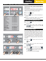
Explanation of pictograms
Danger! Situation presenting immediate danger,
or a hazardous situation which could cause injury
or death.
Danger: risk of burns
Danger: fire hazard!
Consult other chapter
Danger: electric shock!
Tips and useful information
The installation and user instructions are valid for all models unless otherwise specified by the following pictograms:
English
Instructions valid only for GAS ovens
Instructions valid only for free-standing ovens
Instructions valid only for countertop ovens
Instructions valid only for free-standing trolley ovens
4
ChefTop™
BakerTop™
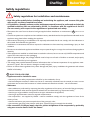
Safety regulations
Safety regulations for installation and maintenance
Read this guide carefully before installing and maintaining the appliance, and conserve this guide
with care for any future consultation of users.
All installation, assembly and non-routine maintenance operation must be performed exclusively by
qualified technicians that are authorized by UNOX, in compliance with the regulations in force in
the user country, with respect to the regulations on systems and work safety.
'LVFRQQHFWWKHRYHQIURPLWVHOHFWULFDODQGJDVVXSSOLHVEHIRUHLQVWDOODWLRQRUPDLQWHQDQFH(
ONLY FOR GAS
OVENS).
&KHFNWKDWV\VWHPVDUHFRPSOLDQWWRWKHLQVWDOODWLRQFRXQWU\VWDQGDUGVDQGWRWKHVSHFLILFDWLRQVLQGLFDWHGRQWKH
appliance rating plate before installing the appliance.
,QWHUYHQWLRQVWDPSHULQJRUPRGLILFDWLRQVQRWH[SUHVVO\DXWKRUL]HGWKDWGRQRWFRPSO\ZLWKWKHLQGLFDWLRQVLQ
this manual shall invalidate the guarantee.
,QVWDOODWLRQRUPDLQWHQDQFHWKDWIDLOVWRUHVSHFWWKHLQGLFDWLRQVLQWKLVPDQXDOPD\FDXVHGDPDJHLQMXU\RUIDWDO
accidents.
3HUVRQVQRWLQYROYHGZLWKDSSOLDQFHLQVWDOODWLRQPD\QRWSDVVWKURXJKRURFFXS\WKHZRUNDUHDGXULQJDSSOLDQFH
assembly.
,IWKHHTXLSPHQWLVLQVWDOOHGRQZKHHOEDVHVRUVWDFNHGLQFROXPQVEHVXUHWRXVHRQO\812;FRPSRQHQWVDQG
respect the instructions on their packaging.
*LYHQLWVSRWHQWLDOGDQJHUWKHSDFNDJHPDWHULDOPXVWEHNHSWRXWRIUHDFKRIFKLOGUHQRUDQLPDOVDQGSURSHUO\
disposed of as called for by local regulation.
7KHUDWLQJVSODWHSURYLGHVHVVHQWLDOWHFKQLFDOLQIRUPDWLRQWKDWLVRIXWPRVWLPSRUWDQFHIRUDQ\DSSOLDQFHPDLQtenance or repairs. Do not remove, damage or modify the plate.
)DLOXUHWRIROORZWKHVHUHJXODWLRQVPD\FDXVHGDPDJHDQGIDWDOLQMXU\LQYDOLGDWHVWKHJXDUDQWHHDQGUHOLHYHV
UNOX of all liability.
ONLY FOR GAS OVENS
Appliances must be installed in areas:
- that comply to the safety requirements called for by the standards in force;
- that have adequate ventilation. Make sure that air is continually refreshed from the outside to ensure correct
combustion and to avoid the formation of volatile substances hazardous to health - risk of suffocation!
Make sure:
- that installation is performed by respecting the safety regulations of the country of use and of the gas company;
WKDWWKHYHQWLODWLRQLQOHWVDQGWKHDSSOLDQFHH[KDXVWVDUHQRWREVWUXFWHGHJREMHFWVDQGZDOOV
- that the type of gas available corresponds to the type indicated on the appliance;
- that the gas pipe diameters meet the required measurements;
- that components - not supplied by UNOX - used for installation comply with the regulations in force of the
country of use;
- that the connection pipe pressure equals that of the gas supply inlet;
- that maximum gas piping inlet pressure is 60 mbar; pressures may not exceed this threshold.
After connection to the gas supply, check for perfect airtightness of the components by preferably
using non-corrosive foams. Never use flames!
5
English
$WDSSOLDQFHFRPPLVVLRQLQJWHVWEXUQHUH[KDXVWJDVHVVWHDPDQGKRWDLU&2&22UHFRUGLQJWKHUHJLVWHUHG
values on the appliance. The burner settings must be checked and adjusted by a specialised technician for values
of non-diluted CO greater than 1000 ppm.
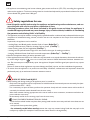
Safety regulations for use
Read this guide carefully before using the appliance and performing routine maintenance, and conserve this guide with care for any future consultation of users.
Following procedures other than those indicated in this guide to use and clean the appliances is
considered inappropriate and may cause damage, injury or fatal accidents; in addition to invalidating
the guarantee and relieving UNOX of all liability.
7KLVDSSOLDQFHFDQRQO\EHXVHGIRUFRRNLQJIRRGE\TXDOLILHGLQVWDOOHULQLQGXVWULDODQGSURIHVVLRQDONLWFKHQVXSRQ
completion of scheduled training courses; all other uses are not compliant to the scope of use and therefore
hazardous.
In particular, the appliance can be used for:
FRRNLQJ3DVWU\DQG%UHDGJRRGVZKHWKHUIUHVKRUIUR]HQBakerTop™;
FRRNLQJRI*DVWURQRPLFSURGXFWVZKHWKHUIUHVKRUIUR]HQChefTop™
VWHDPFRRNLQJPHDWILVKDQGYHJHWDEOHVChefTop™
- cooking vacuum-packed food in bags which are suited to that type of cooking procedure;
EULQJLQJFKLOOHGDQGIUR]HQIRRGEDFNWRQRUPDOWHPSHUDWXUHBakerTop™ - ChefTop™
0RQLWRUWKHDSSOLDQFHGXULQJLWVHQWLUHRSHUDWLRQF\FOH
,IWKHDSSOLDQFHGRHVQRWIXQFWLRQRULIWKHUHDUHDQ\IXQFWLRQDORUVWUXFWXUDODOWHUDWLRQVGLVFRQQHFWWKHHOHFWULFity, water and gas supplies (
ONLY FOR GAS OVENS) and contact a UNOX authorized customer assistance service. Do not attempt to independently repair the appliance. Request UNOX original spare parts for any repairs
necessary.
)DLOXUHWRREVHUYHWKHVHUHJXODWLRQVPD\FDXVHGDPDJHDQGIDWDOLQMXULHVDQGDOVRLQYDOLGDWHVWKHJXDUDQWHH
7R HQVXUH WKDW WKH DSSOLDQFH LV LQ SHUIHFW XVH DQG VDIHW\ FRQGLWLRQV PDLQWHQDQFH DQG LQVSHFWLRQV VKRXOG EH
performed yearly by an authorised customer assistance service.
RISK OF BURNS and INJURY!
:KLOHFRRNLQJDQGGXULQJFRROLQJRIDOODSSOLDQFHSDUWVEHFDUHIXOWR
2QO\WRXFKWKHDSSOLDQFHFRQWUROFRPSRQHQWVRUKDQGOHEHFDXVHWKHH[WHUQDOSDUWVDUHH[WUHPHO\KRWWHPSHUDWXUHDERYH&)
- If it is necessary to open the door, perform this operation slowly and with utmost caution while careful of
extremely hot exhaust steam released from the oven cavity.
- Wear heat resistant clothing appropriate to the use at hand to move containers, accessories and other objects inside the oven cavity.
- Be extremely careful when removing trays from the oven cavity.
ONLY FOR FREE-STANDING TROLLEY OVENS:
ORFNWKHIURQWZKHHOEUDNHVLQWRSODFHDIWHUSXWWLQJORDGVLQWRWKHRYHQFDYLW\DQGHDFKWLPHWKHVHDUHQRW
to be moved;
DOZD\VORFNWKHWUD\VLQWRWKHLUJXLGHV
be extremely careful when moving because the trays may contain boiling fluids that may spill or the
WUROOH\VPD\FDSVL]HIRUH[DPSOHLIPRYHGDFURVVXQHYHQIORRUVRUWKURXJKGRRUV
English
6
ChefTop™
BakerTop™
([WUDFWWKHSUREHIURPWKHFRUHRIIRRGVEHIRUHUHPRYLQJWUD\VIURPWKHRYHQDQGSODFHLWLQWKHH[WHUQDOSUREH
holder. Before extracting the tray check that the probe cable is not in the way. Handle the probe with care
because it is extremely sharp and, after use, reaches high temperatures.
'XULQJ´&22/µPRGHRYHQFDYLW\FRROLQJWKHDSSOLDQFHDOVRIXQFWLRQVZKLOHWKHGRRULVRSHQ
Do not remove or touch the protective fan casing, the fans and the heating elements while the appliance is on
and until complete cooling.
'RQRWRSHQWKHRYHQGRRUGXULQJFOHDQLQJLQRUGHUWRDYRLGULVNVRILQMXULHVFDXVHGE\LPSHOOHUPRYHPHQWKRW
steam and aggressive action of chemical detergents used.
RISK OF FIRE!
%HIRUHXVLQJWKHDSSOLDQFHPDNHVXUHWKDWQRQRQFRPSOLDQWREMHFWLQVWUXFWLRQPDQXDOSODVWLFEDJVRURWKHU
or detergent residue is not inside the oven cavity; likewise, make sure that the smoke exhaust is free of obstructions and that no flammable materials are in its vicinity.
'RQRWSODFHVRXUFHVRIKHDWLHJULOOVIU\HUVHWFKLJKO\IODPPDEOHVXEVWDQFHVRUIXHOVLQWKHYLFLQLW\RIWKHDSSOLDQFHLHJDVROLQHSHWUROERWWOHVRIDOFRKROHWF
'RQRWXVHKLJKO\IODPPDEOHIRRGRUOLTXLGVZKLOHFRRNLQJH[DOFRKRO
$OZD\VNHHSWKHRYHQFDYLW\FOHDQSHUIRUPLQJGDLO\FOHDQLQJRUDIWHUHDFKFRRNLQJVHVVLRQIDWVRUIRRGUHVLGXH
left inside the appliance could ignite!
RISK OR ELECTRICAL SHOCK
'RQRWRSHQWKHFRPSDUWPHQWVPDUNHGZLWKWKHVHV\PEROVDFFHVVLVUHVHUYHGWRTXDOLILHGLQVWDOOHUDXWKRULVHG
by UNOX.
)DLOXUHWRREVHUYHWKLVUHJXODWLRQLQYDOLGDWHVWKHJXDUDQWHHDQGPD\FDXVHGDPDJHDQGIDWDOLQMXULHV
ONLY FOR GAS OVENS
$OZD\VPDLQWDLQWKHVPRNHH[KDXVWSLSHIUHHRIREVWUXFWLRQVHJREMHFWVWUD\VHWFWKDWLVORcated on the top portion of the oven.
$OZD\VVZLWFKRQWKHKRRGZKHQXVLQJWKHDSSOLDQFHLILQVWDOOHG
,IWKHDSSOLDQFHLVFRQQHFWHGWRDVPRNHIOXHWKLVPXVWEH
- kept free of any obstructions - risk of fire!
- regularly cleaned and inspected as called for by the relative standards of the country of use - risk of fire!
7KHDSSOLDQFHPXVWEHLQVWDOOHGIDUIURPDLUFXUUHQWVRUGUDIWVULVNRIILUH
Make sure that ventilation inlets and the underlying part of the appliance are clean and free of obVWUXFWLRQVHJREMHFWVQHDUWKHDSSOLDQFH
,IWKHRGRXURIJDVLVGHWHFWHG
- immediately cut-off the gas supply;
- immediately air out the area;
- do not engage any electrical switch or provoke sparks or flames;
- use an external telephone to contact the gas utility company.
7
English
INSTRUCTIONS FOR THE INSTALLER
Contents
Unpacking _______________________________________________________________________________ 9
Removing the protective film and silicone cap ___________________________________________________12
Checking pack contents ____________________________________________________________________12
Getting started ___________________________________________________________________________14
Positioning _______________________________________________________________________________15
Characteristics of installation area ____________________________________________________________15
Appliance distances ________________________________________________________________________17
Positioning - COUNTERTOP OVENS _________________________________________________________18
Positioning: Floor or wheeled-bases _______________________________________________________18
Positioning: substructures ________________________________________________________________19
$QFKRULQJRQXVHU
VVXEVWUXFWXUHLHVWHHOWDEOHVHWF________________________________________19
Anchoring to UNOX substructures ________________________________________________________19
3RVLWLRQLQJDSSOLDQFHVWDFNLQJ0D[L/,1. __________________________________________________21
Positioning - FREE-STANDING OVENS WITH/WITHOUT TROLLEY _______________________________22
Levelling the appliance ___________________________________________________________________22
Adjustments _____________________________________________________________________________24
Door closure adjustment ___________________________________________________________________24
Electrical connection _______________________________________________________________________26
Checks _______________________________________________________________________________27
Adapting to different voltages _____________________________________________________________27
Replacing the power supply cable __________________________________________________________27
Gas connection ___________________________________________________________________________28
Connecting to the gas utility system ________________________________________________________28
Adapting to different gas supplies __________________________________________________________28
Post-connection checks __________________________________________________________________31
Plumbing ________________________________________________________________________________32
Plumbing: water supply __________________________________________________________________32
Water supply: specifications_______________________________________________________________33
Plumbing: water drainage ________________________________________________________________34
Drainage: specifications __________________________________________________________________35
Plumbing: interventions __________________________________________________________________35
Smoke exhaust - ELECTRIC OVENS __________________________________________________________38
Smoke and gas exhaust - GAS OVENS _________________________________________________________39
&RQQHFWLQJVWDFNHGDSSOLDQFHV0$;,/LQN ____________________________________________________40
Connecting appliance with RJ45 cable _______________________________________________________40
6HWWLQJRYHQVDV´0$67(5µRU´&21752//('µ ____________________________________________40
Connecting the external USB interface kit and safety thermostat reset_____________________________42
English
8
ChefTop™
BakerTop™
Before installing the appliance carefully read chapter “Safety regulations“ at page 5 and
chapter “Forward” at page 4.
'XULQJLQVWDOODWLRQZHDUSURSHUSURWHFWLYHFORWKLQJSURWHFWLYHIRRWZHDUJORYHVHWF
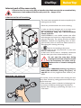
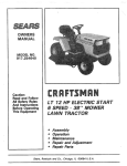
Unpacking
Check the package at reception for any visible
damage. If damage is found, promptly contact
UNOX and DO NOT install the appliance.
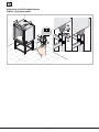
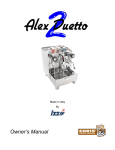
Before transporting the appliance to its installation point, make sure that:
- it easily passes through doorways;
- the floor supports its weight.
Transport must be exclusively performed by meFKDQLFDOPHDQVLHWUDQVSDOOHWOLIWHU
People necessary
for installation:
120 Kg
OK
OK
9
English
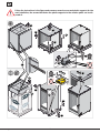
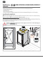
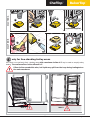
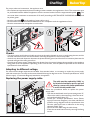
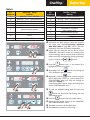
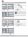
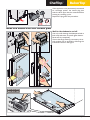
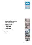
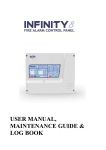
Follow the instructions in the figure and conserve several screws and plastic supports for the
next installation; the screws that fasten the plastic supports to the wooden pallet can be disposed of.
2
4
3
3
3
METAL
5
1
6
METAL
3
1
4
2
4
4
5
English
10
7
ChefTop™
BakerTop™
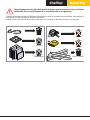
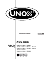
The packaging materials, given their potential danger, must be kept out of reach of children
and animals, and correctly disposed of in compliance with local regulations.
UNOX has followed the NON-STEP Efforts philosophy for years to increase the environmental computability of
its products to reduce energy consumption and wastes.
UNOX wishes to protect the environment and invites the consumer to dispose of waste in recycling bins.
NYLON
x4
x2
WOOD
POLYESTYRENE
CARDBOARD
11
English
Removing the protective film and silicone cap
Slowly detach the protective films from the appliance:
clean any glue residue with appropriate solvents without using tools, abrasive detergents or acids that could
ruin the surfaces.
The removed film, given its potential danger,
must be kept out of reach of children and
animals; and correctly disposed of in compliance with local regulations.
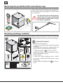
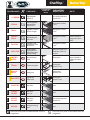
Checking package contents
Before installing the appliance, check that the following
packaged components are present and free of damage:
x4
COUNTERTOP OVENS
- oven with rear side ready for:
HOHFWULFDOFRQQHFWLRQVSRZHUVXSSO\FDEOHDOUHDG\
DVVHPEOHG
SOXPELQJZDWHUVXSSO\SLSHPHFKDQLFDOILOWHU
ILWWLQJZLWKQRQUHWXUQYDOYHDOUHDG\DVVHPEOHG
x1
ISH
ENGL
NO
ITALIA
ual
man
ion
one
ruct
ruzi
Inst
g
d'ist
isun
uale
nwe
Man
ngsa
tion
ienu
Bed
tilisa
s
d’U
ione
ice
rucc
Not
Inst
ual
Man
x
xxx
xxx
xxx
SCH
DEUT
ÇAIS
FRAN
OL
ESPAÑ
x
xxxxx
XB
XV-
x8
x1
For technician: cut and paste the correct current setting label
Per l’installatore: tagliare ed attaccare la corretta etichetta di settaggio
2E
G20
20 mbar
2E+
G20/G25
20/25 mbar
2H
G20
20mbar
2H
G20
25 mbar
2L
G25
25 mbar
2LL
G25
20 mbar
2S
G25.1
25 mbar
3+
G30 /G31
28-30/37 mbar
3B/P
G30 /G31
28-30 mbar
3B/P
G30 /G31
37 mbar
3B/P
G30 /G31
50 mbar
English
x1
x1
x1
/3*JDVFRQQHFWLRQ(
ONLY FOR GAS OVENS)
- technical GRFXPHQWV XVH DQG LQVWDOODWLRQ PDQXDO
WHFKQLFDOVSHFLILFDWLRQVVKHHW
- 4 plastic supports;
- 1 ´6WDUWHU .LWµ EDJ 8 self-tapping screws, 1 attachment wrench, 1 falling liquid warning sticker, 1 conical
H[KDXVWSOXJ
- PHWKDQHQR]]OHDQGVHWWLQJVVWLFNHU
OVENS)
Methane G20,G25,G25.1
12
ONLY FOR GAS
ChefTop™
BakerTop™
FREE-STANDING OVENS WITHOUT TROLLEY
x2
x1
ISH
ENGL
NO
ITALIA
ual
man
ion
one
ruct
ruzi
Inst
g
d'ist
isun
uale
nwe
Man
ngsa
tion
ienu
Bed
tilisa
s
d’U
ione
ice
rucc
Not
Inst
ual
Man
x
xxx
xxx
xxx
XB
XV-
x1
x1
For technician: cut and paste the correct current setting label
Per l’installatore: tagliare ed attaccare la corretta etichetta di settaggio
2E
G20
20 mbar
2E+
G20/G25
20/25 mbar
2H
G20
20mbar
2H
G20
25 mbar
2L
G25
25 mbar
2LL
G25
20 mbar
2S
G25.1
25 mbar
3+
G30 /G31
28-30/37 mbar
3B/P
G30 /G31
28-30 mbar
3B/P
G30 /G31
37 mbar
3B/P
G30 /G31
50 mbar
SCH
DEUT
ÇAIS
FRAN
OL
ESPAÑ
x
xxxxx
x1
x1
- oven with rear side ready for:
HOHFWULFDOFRQQHFWLRQVSRZHUVXSSO\FDEOHDOUHDG\
DVVHPEOHG
SOXPELQJZDWHUVXSSO\WXEHPHFKDQLFDOILOWHU
attachment with non-return valve already assemEOHG
/3*JDVFRQQHFWLRQ(
ONLY FOR GAS OVENS)
- WUD\KROGHUWUROOH\VRQO\PRGHOV;%&(;9&
(3;9&(3
- technical GRFXPHQWV XVH DQG LQVWDOODWLRQ PDQXDO
WHFKQLFDOVSHFLILFDWLRQVVKHHW
- 2 plastic floor supports;
- 1 ´6WDUWHU.LWµEDJ1 attachment wrench, 1 falling liquid warning sticker, 1 FRQLFDOH[KDXVWSOXJ
- 2 PHWKDQHQR]]OHDQGVHWWLQJVVWLFNHU
GAS OVENS)
ONLY FOR
Methane G20,G25,G25.1
Contact UNOX if any pieces are missing.
Different auxiliary instruments are available as professional completion of the BakerTop™and
ChefTop™ ranges: contact UNOX for additional information.
13
English
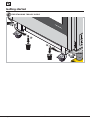
Getting started
FREE-STANDING TROLLEY OVENS
1
2
2
1
English
14
ChefTop™
BakerTop™
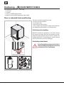
Positioning
Characteristics of the installation area
Max 35°C
Max 70%
Min 5°C
Install the appliance in areas:
- dedicated and conform to cooking industrial foods;
- having adequate air ventilation;
- that comply with the laws in effect on system and
work safety;
- protected against atmospheric agents;
- with temperatures between +5° to +40°C maximum;
- having a maximum humidity of 70%.
The law requires gas appliances to be installed in
areas:
- with surface area and ventilation suitable for oven
power;
- with outdoor evacuation of exhaust gas.
For additional information consult chapter Smoke
and gas exhaust at page 39.
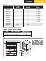
Table A
MODELS
BakerTop™
XBC 1005E - EL
XBC 905E - EL
XBC 805E
XBC 605E
XBC 405E
XBC 1015GE-EGL
XBC 915EG - EGL
XBC 815EG
XBC 615EG
Size
mm
866x972x1866
866x972x1866
860x882x1217
860x882x897
860x882x709
866x970x2072
866x970x2072
860x882x1425
860x882x1105
Weight*
kg
177
183
121
89
63
200
206
135
109
Do not install the appliance near others
that reach high temperatures in order
to avoid damaging electric parts.
The appliance cannot be recess installed.
Make sure that the floor supports the weight of
WKHDSSOLDQFHDWIXOOFDSDFLW\VHH´Table A” and
“Table B”
For additional technical information on the appliance, consult the "technical specifications"
sheet attached to the appliance.
Table B
MODELS
ChefTop™
Size
mm
Weight*
kg
MODELS
ChefTop™
Size
mm
Weight*
kg
XVC 4005EP -EPL
XVC 2005EP
XVC 1205EP
XVC 1005EP - EPL
XVC 905EP - EPL
XVC 705E
XVC 705EP
XVC 505E
XVC 505EP
XVC 305EP
XVC 305P
869x1206x1857
860x1135x1217
860x1135x897
866x972x1866
866x972x1866
750x773x1042
750x773x1042
750x773x895
750x773x895
750x773x707
750x773x707
190
165
150
177
183
86
86
79
79
62
62
XVC 105E
XVC 105EP
XVC 205E
XVC 055E
XVC 4015EG - GL
XVC 1215EG
XVC 1015EG - EGL
XVC 915EG - EGL
XVC 715EG
XVC 515EG
XVC 315EG
750x782x498
750x782x498
574x773x632
574x762x498
869X1206X2072
860x1135x1105
866X972X1866
866X972X1866
750x773x1254
750x773x1107
750x773x918
45
45
44
38
220
170
200
206
100
93
76
* the values refer to the appliance when empty
15
English
7KHLQVWDOODWLRQDUHDVPXVWEHHTXLSSHGZLWKHOHFWULFDOSOXPELQJDQGJDVXWLOLWLHVRQO\IRUJDVRYHQVWKDWFRPSO\
with the regulations on system and work safety of the country of use.
The figure gives indicative connection measurements:
- electrical connection
- plumbing
FRQQHFWLRQWRWKHJDVVXSSO\RQO\IRUJDVPRGHOV
H[KDXVWS
IORRUH[KDXVWSP
10 cm
60 cm
85 cm
130 cm
S
7 cm
10 cm
60 cm
130 cm
7 cm
10 cm
S
10 cm
10 cm
60 cm
130 cm
60 cm
85 cm
130 cm
10 cm
SP
45 cm
English
SP
45 cm
16
ChefTop™
BakerTop™
Appliance distances
Position the appliance respecting the distances in the
figure and so that the back wall is easily accessible for
appliance connections and maintenance.
m
5 cin.
m
m
5 cin.
m
n.
micm
90
Do not install the appliance near easily
inflammable or heat sensitive materials,
walls or furniture. Otherwise, protect
them with appropriate non-inflammable
materials in compliance with fire prevention
regulations.
m
5 cin.
m
FLAMERESISTANT
PANEL
n.
mi m
c
5
m
45 in.
cm
m
45 in.
cm
n.
micm
0
7
For safety reasons, the last tray should
NEVER be placed at a height greater
than 160 cm.
If necessary to do so, it is mandatory to
post the sticker contained in the "Starter Kit" at
the height shown in the figure.
160 cm
Starter Kit
17
English
Positioning -
COUNTERTOP OVENS
The countertop ovens can be positioned:
- on the floor;
- on wheels;
- on own or UNOX substructures;
VWDFNHGRQRWKHU812;DSSOLDQFHV0D[L/,1.
Floor or wheeled-base positioning
The floor beneath the appliances must:
- be flame and heat resistant;
- be perfectly level;
- have a flat and even surface;
- able to support the appliance weight at full load without undergoing deformation or structural failure.
Positioning: free-standing
DO NOT position the appliances on the floor directly
but remove the plastic feet from the appliance and assemble the steel support feet H.140 mm. UNOX. For
detailed information on assembling the support feet Kit
read the instructions on the kit packaging.
Positioning: wheel bases
Move the appliance using only the UNOX
wheel kit and by following the instructions
contained on the kit packaging.
x4
English
18
ChefTop™
BakerTop™
Positioning: substructures
Before anchoring on a UNOX substructure or on one of your own, always check that the
substructure is perfectly flat using a spirit or digital level. If otherwise, the UNOX
substructure can be levelled by acting on the feet, making sure to avoid completely
unscrewing them.
Anchoring on user's substructure (i.e. steel tables, etc...)
x8
5
4
3
x8
2
1
x4
7
6
OK!
Anchoring on UNOX substructures
(UNOX - provers, blast-coolers, or neutral cabinets/Pollo)
1
3
x8
4
2
19
5
x4
English
Anchoring on UNOX substructures
(UNOX - high open stand)
1
3
4
2
English
20
x4
ChefTop™
BakerTop™
Positioning: appliance stacking (Maxi.LINK)
Use UNOX's oven stacking kit when stacking several units.
It maintains the proper distance between appliances and simplifies electrical, plumbing and exhaust connections.
Follow the instructions on the oven stacking kit for kit assembly.
The oven should never be placed immediately above other ovens or other sources of heat.
The oven stacking kit also contains an RJ45 cable, a siphon and a Tee fitting for plumbing several appliances with a single water intake.
)RULQIRUPDWLRQRQKRZWRLQWHUFRQQHFWVWDFNHGDSSOLDQFHVRUDGGLWLRQDODFFHVVRULHVSURYHUVKRRGV
RVPRVLVNLWVHWFDQGLQVWDOODWLRQRIWKHRJ45 cable consult chapter “Connecting stacked appliances
0$;,/LQNµ at page 40.
BakerTop™
ChefTop™
Examples of possible compositions:
21
English
Positioning TROLLEY
FREE-STANDING OVENS WITH/WITHOUT
Ovens of this type must exclusively be set on floors that meet the following requirements:
- be flame and heat resistant;
- be perfectly level;
- have a flat and even surface;
- are able to support the appliance weight at full load without undergoing deformation or structural failure.
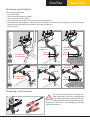
Levelling the appliance
n Make sure that the length of the oven cavity diagonals are the same; if this is not the case, it implies that the appliance is not flush-> o level it by adjusting the height of the 4 feet.
Minimum height from the ground must be 173 cm. to allow the trolley easy access.
Once level,FKHFNWRVHHWKDWWKHWUROOH\HQWHUVHDVLO\LQWRWKHRYHQFDYLW\ZLWKRXWHQFRXQWHULQJREVWDFOHVHJ
IORRULUUHJXODULW\DQGZLWKRXWEUXVKLQJDJDLQVWWKHERWWRPVXUIDFHRIWKHRYHQFDYLW\
Further adjust the feet if necessary.
Finish by compulsorilyDQFKRULQJWKHIURQWVXSSRUWVWRWKHIORRUWRDYRLGFDSVL]LQJVHH
ILJXUHRQWKHIROORZLQJSDJH
3
MIN
173 mm
0c
16
m
0c
16
m
2
1
2
English
22
ChefTop™
BakerTop™
SOLUTION B
SOLUTION A
3
6
5
4
1
2
screws not supplied
2
3
1
11 12 1
10
2
3
9
4
8
7 6 5
5 24h
4
only for free-standing trolley ovens
If the floor is not perfectly flush, a loading ramp with a maximum incline of 4° may be used to simplify trolley
loading. The maximum floor incline allowed is 2°.
If floor incline exceeds this value, hot liquids may spill from the trays during loading/extraction and cause burns.
MAX 4°
MAX 2°
23
English
Adjustments
Door closure adjustment
After positioning the oven, proceed as follows if the door handle fails to close in the correct upright position:
n check that the appliance is flush by using a spirit or digital level;
o-t if the appliance is level, adjust the closure latch as shown in the following figures.
If the problem persists, repeat this procedure, loosening the latch fixing screws further.
1
3
2
OK!
4
7
6
5
English
24
OK!
ChefTop™
BakerTop™
4
3
2
OK!
5
9
7
10
8
6
11
25
English
Electrical connections
Before installing the appliance carefully read chapter “Safety regulations“ at page 5.
LI2293A0 - Printed: 06-2012
Subject to technical changes.
Connections to the power main and the electrical system must comply with the regulations in force
in the country of installation of the appliance; and all connections must be performed by qualified
installer authorised by UNOX. Failure to comply with these regulations may cause damage and injuries, invalidates the guarantee and relieves UNOX of all liabilities.
Electrical connections should be performed by mounting a
SRZHU SOXJ QRW VXSSOLHG RI W\SH DQG ORDG DGHTXDWH WR WKH
maximum power absorbed by the oven's phases A GDWD
DYDLODEOH RQ WKH DWWDFKHG ´7HFKQLFDO VSHFLILFDWLRQVµ VKHHW ,I
XBC
this is not possible, the wiring cables supplied by UNOX are
sufficient for direct connection to the electrical board B .
Before connecting the appliance to the electricity mains, always compare the power supply data with that of the appliance specified on the rating plate.
The appliance has its power cable already factory mounted to
the terminal board; for different power and voltage requirements consult chapter Adapting to different voltage at
page 27.
Oven having only a single-phase Schuco plug may not undergo
any other type of electrical connection and no dimensional
modification of the cable other than extensions, replacing it
only with one having specifications equal to the original facThe wiring diagrams, the wire specifications and
WRU\ FDEOH W\SH RI UXEEHU FURVVVHFWLRQ HWF DOO VSHFLILFDWKHWHFKQLFDOGDWDDUHLQGLFDWHGRQWKH´7HFKQLFDO
tions are listed on the "Technical Specifications" sheet attached
VSHFLILFDWLRQVµVKHHWDWWDFKHGWRWKHDSSOLDQFH
to the appliance.
- Italy
e (PD) .555
negh 86.57
Cado 049
0 - +39
. - 3501- Fax: x.com
22 .511 .uno
X S.p.A
rana,86.57 www
UNO
Majo049
.com
Via 39
Tel.:+ unox
info@
A
OMNIPOLAR CIRCUIT
BREAKER
THERMAL + MAGNETO-THERMAL BREAKER
B
English
26
ChefTop™
BakerTop™
For proper electrical connections, the appliance must:
- Be wired into an equipotential system according to what is stated in the regulations in force. This connection must
. The
be performed between different appliances with the terminal marked with the equipotential symbol
ZLUHPXVWKDYHDPD[LPXPFURVVVHFWLRQRIPPDFFRUGLQJWR,(&(1VWDQGDUGDQG
be yellow-green.
- Must be grounded
WRWKHHDUWKLQJJUHHQ\HOORZZLUH
- Must be connected to a thermal differential switch as in compliance with the regulations in force.
- Must be connected to an omnipolar circuit breaker.
Checks
- The copper jumper and the electrical cable must be secured together beneath the screw in its tightening direction; and the
electrical connections must be well secured before connecting the appliance to the electricity mains.
- check for any electrical dispersion between the phases and the ground, and for electrical continuity between the
external casing and the main ground line.
- Check that the power supply voltage does not deviate from the nominal voltage value specified on the appliance
rating plate when the appliance is operating. If this is not the case, wire the phases as specified on the "technical
specifications" sheet attached.
Adapting to different voltage
For electrical and voltage requirements that differ from standard values, it is necessary to replace the power supply
cable and connect the new cable to the terminal board following the diagrams on the ´7HFKQLFDOVSHFLILFDWLRQVµVKHHW
3RZHUVXSSO\&RQQHFWLRQ'LDJUDP attached to the appliance.
Replacing the power supply cable
B
A
The cable must be replaced by UNOX or
by its technical assistance service, and in all
cases by a person with similar qualification
in order to avoid possible risks.
Follow the procedures below to replace the power
supply cable:
RSHQWKHWHUPLQDOERDUGFRYHUE\XQVFUHZLQJVFUHZ´$µ
- remove the cable by disconnecting it from the termiQDOERDUGDQGFDEOHFODPS´%µ
- consult the "Technical Specifications" sheet 3RZHU
supply-Connection Diagram: the sheet indicates all
possible wiring diagrams and the specifications that
the new cable must have in reference to the wiring
selected&DEOH7\SH;
- secure the new cable using the cable clamp;
- Close the terminal board cover by securing the fixing
screws.
27
English
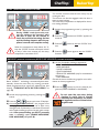
LPG gas connection
(
only for gas ovens)
Before installing the appliance carefully read chapter “Safety regulations“ at page 5.
Connections to the gas supply and the gas utility lines must comply with the regulations in force in
the country of installation of the appliance; and all connections must be performed by qualified installer authorised by UNOX. Failure to comply with these regulations may cause damage and injuries, invalidates the guarantee and relieves UNOX of all liabilities.
Connecting to the gas utility system
cut-off valve
not supplied
injector
3/4” female
fitting
The appliance is factory set, configured and tested to
operate using:
/3*JDVEXWDQHSURSDQHW\SH**
- nominal pressure of 28/30/37 mbar.
- maximum gas inlet pressure of 55 mbar.
Make sure that the gas supply and pressures comply with
DERYHLQGLFDWLRQVEHIRUHFRQQHFWLQJWKHDSSOLDQFHZKLFK
DUHDOVROLVWHGRQWKHVSHFLILFDWLRQVODEHORWKHUZLVHFRQsult chapter “Adapting to different gas supplies“
The 3/4" female type attachment for connection to the
gas utilities is in the back of the oven: the oven must be
FRQQHFWHGXVLQJDIOH[LEOHSLSHZLWKDFXWRIIYDOYHQRW
VXSSOLHGSODFHGXSVWUHDPRIWKHDSSOLDQFH
hose not
supplied
Make sue that the piping does not run
next to hot areas and that they are not
subject to pulling, twisting or crushing
forces.
Components sealed with red paint must
never be adjusted!
Unox provides upon customer request an
adapter whose diameter varies in relation
to oven model to connect the evaacuation switch to the wind deflector device.
The gas supply system and all attachments must be up to code and respect
the regulations in force in the country of
use.
Adapting to different gas supplies
CHANGING INJECTOR
13
C
H
English
B
A
Operations to adapt the oven to another type of gas must be exclusively performed by qualified installer authorised
by UNOX.
Shut the cut-off valve, disconnect power and check that the
diameter of the replacement injector in 1/100 mm matches
the value printed onto it.
Unscrew and remove injector C using a 13 mm spanner.
Install a new injector that is suitable to the type of gas
XVHGVHH “Table C” columns A and B
Loosen screw "A".
Position bushing "B" at distance H in relation to the injecWRUXVHGVHH “Table C” column C
/RRVHQVFUHZ$RQFHDJDLQ
28
ChefTop™
BakerTop™
Table C
MODELS
XBC615EG
XBC815EG
XVC315EG
XVC515EG
XVC715EG
XVC1215EG
XVC2015EG
Ø INIJECTOR
[1/100 mm]
column B
345
225
375
235
275
180
330
215
360
230
345
225
375
235
340
GAS
column A
G20, G25, G25.1
G30, G31
G20, G25, G25.1
G30, G31
G20, G25, G25.1
G30, G31
G20, G25, G25.1
G30, G31
G20, G25, G25.1
G30, G31
G20, G25, G25.1
G30, G31
G20, G25, G25.1
G30, G31
G20, G25, G25.1
XVC915EG
XVC1015EG
XBC915EG
G30, G31
XBC1015EG
G30, G31
XVC4015EG
Gas nozzles G30 and G31 are installed on all models
225
225
BUSHING B DISTANCE
column C
H = 39mm
H = 39mm
H = 39mm
H = 39mm
H = 39mm
H = 39mm
H = 39mm
H = 39mm
H = 39mm
Table D - Gas valve outflow pressure
GAS
MAX pressure[mbar]
MIN pressure[mbar]
G20
14,2 ± 2%
7
G 25 - G25.1
21,2 ± 2%
10
G30 - G31
26,2 ± 2%
13
SETTINGS LABEL
At installation and after
every adaptation to gas
type, remove the indelible
sticker shown in the figure
from the Starter Kit and
GAS PARAMETER
cut out the settings label
ADJUSTMENTS AT
that has the new gas parameters. The sticker must
be applied onto the data
plate.
For technician: cut and paste the correct current setting label
Per l’installatore: tagliare ed attaccare la corretta etichetta di settaggio
2E
G20
20 mbar
2E+
G20/G25
20/25 mbar
2H
G20
20mbar
2H
G20
25 mbar
2L
G25
25 mbar
2LL
G25
20 mbar
2S
G25.1
25 mbar
3+
G30 /G31
28-30/37 mbar
3B/P
G30 /G31
28-30 mbar
3B/P
G30 /G31
37 mbar
3B/P
G30 /G31
50 mbar
LI2293A0 - Stampato: 01-2012
XBC
om
x.c
no
w.u
ww
29
English
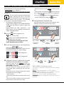
CONTROL PANEL
1
5 sec.
2
4
3
5
6
n Enter the hidden menu by si-
7
multaneously pressing the two
buttons
onds.
10 sec
for 5 sec-
Press the
button until
calling up the display: 12 - FrU
o
Press the
button until
calling up "GAS" on the screen.
p
q Press the
EXWWRQVXQWLOVHOHFWLQJWKHJDVXVHGFDXWLRQ*DOVRLQFOXGHVW\SH*DQG*
LQFOXGHVW\SH*
r
To save changes hold the
s Exit by pressing the
button for 5 seconds until to hear acoustic signal confirmation
button.
t Permanently confirm the new type of gas parameters by disconnecting the power from
the oven for 10 seconds and then restoring it.
Failure to perform this last step will result in NO gas configuration save. In this case, the
procedure must be repeated from step n.
English
30
ChefTop™
BakerTop™
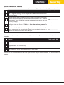
Post-connection checks
Check the items listed in the table after connecting the oven to the gas utility or after adjusting to a new type of gas.
¥
Check:
Check result
The air-tightness of the gas circuit using NON-CORROSIVE foam substances.
Never use flames!
1RPLQDOVXSSO\SUHVVXUHXVLQJDIOXLGSUHVVXUHJDXJHHJDHOHFWULFPDQRPHWHU
,IYDOXHVGHWHFWHGGHYLDWHIURPPLQDQGPD[SUHVVXUHOLVWHGLQWKH´7HFKQLFDO
mbar.........................
6SHFLILFDWLRQVµVKHHWCHART ADWWDFKHGWRWKHDSSOLDQFHFRQWDFWWKHORFDO
gas utility company.
The gas valve outflow pressure.
min mbar................
Compare values with those of “Table D - Gas valve outflow pressure” at
max mbar................
page 29.
The values of CO - CO2 of the exhaust gas and record values detected. The
burner settings must be checked and adjusted by a specialised technician for ppm.........................
values of non-diluted CO greater than 1000 ppm.
If the tests were positive, power and start-up the appliance, and through the air vents, check the points listed in
the table:
¥
Checks:
Check result - OK
Proper burner ignition
Bright blue flame with no yellow tips
Gas exhaust pipe and air vents clean and free of obstructions
Instruct the user about the basics of safe oven operation with respect to this installation, use and maintenance
manual.
31
English
Plumbing connections
Plumbing: water supply
The rear of the appliance contains:
A PHWHUVRIKRVHPHFKDQLFDOILOWHUDQGµDWWDFKPHQWZLWKQRQUHWXUQYDOYHIRUSOXPELQJ Before connecting the water pipe to the appliance, flush it out with water in order to eliminate any residue which has
accumulated inside it.
A shut-off valve should be positioned between the water mains and the appliance;
B a pipe to supply detergent for cleaning the oven cavity;
C WZRDWWDFKPHQWVIRUFRQQHFWLQJDGGLWLRQDOZDWHUWUHDWPHQWDFFHVVRULHVUNOX.Pure or UNOX.Pure-RO
Follow instruction on the accessory package for connection.
7RVLPSOLI\SOXPELQJLQFDVHVRIPXOWLSOHFROXPQFRQQHFWLRQV0D[L/,1.XVHWKH7HHLQWKH812;RYHQ
stacking kit.
A
R IN
TE
WA
WATER IN
hose L= 1,5m
mechanical
filter
shut-off valve
3/4 attachment
with non-return
valve
Max 30°C
0
15
0
0
10
20
0
50
0
R
TE
WA
IN
25
150÷600kPa
r
ba
NaCl
150 μS/cm
Tee attachment
R
TE
WA
English
IN
32
ChefTop™
inse
&R
et
.D
OX
UN
UNOX.Det&Rinse
Unox.PURE-RO
2
e
.Pur
OX
From
BakerTop™
UN
e
ins
&R
et
.D
OX
UN
To
re
.Pu
OX
UN
e
ur
.P
OX
R IN
TE
WA
m
Fro
1
UN
e
ur
X.P
NO
U
To
R IN
TE
WA
Unox.PURE
e
ur
.P
OX
m
Fro
UN
e
ur
X.P
NO
U
To
B
C
R
TE
WA
IN
Water supply: specifications
The water supply must:
- have a maximum temperature of 30 °C;
- be drinkable;
- have maximum conductivity of 150 μS/cm;
KDYHDSUHVVXUHLQWKHUDQJHRIDQGN3DN3DUHFRPPHQGHG
If the pressureRIWKHZDWHUVXSSO\DWWKHLQOHWLVWRRORZN3DDSXPSZLWKDVXLWDEOHIORZUDWHVKRXOGEHXVHG
PLQLPXPIORZUDWHOKChefTop™ and BakerTop™ ovens have a built-in pressure reducer.
If the water hardnessLVJUHDWHUWKDQWKHYDOXHVSHFLILHG150 μS/cmXVHDGHPLQHUDOL]HUUNOX.Pure or UNOX.
Pure-RORUILOWHUVWRDYRLGOLPHVFDOHDQGRURWKHUPLQHUDOVIURPGHSRVLWLQJLQVLGHWKHRYHQ'DPDJHFDXVHGE\
limescale or other chemical agents carried by the water is not covered by the guarantee.
812;UHFRPPHQGVLWILOWHUV´8QR[385(µRULWVUHYHUVHRVPRVLVNLWZLWK´8QR[385(52µSXPSLI
water pressure is low or water is especially hard. The reverse osmosis kit is directly managed with a selfdiagnostic system from the oven's electronic control system.
Follow the instructions on the packaging of these parts for their assembly/disassembly.
If the appliance cannot be permanently connected to the water mains, a water tank and pump kit for
drawing water from the tank or from another external vessel is available from UNOX.
Unox.PURE-RO
Unox.PURE
33
English
Plumbing: water drainage
The drain is located:
- on the bottom of countertop ovens
- on the back of free-standing ovens with or without trolley
.
Connect the bend/siphon to a rigid pipe or flexible hose and connect the assembly to waste water drainage.
UNOX recommends its proprietary rigid pipes and flexible hoses.
7KHZDVWHZDWHUGUDLQLQJIURPWKHRYHQPD\EHKRW&
The pipes used for water drainage must be able to withstand high temperatures and not be
made of metal.
If it is necessary to lower the temperature of the waste water, UNOX recommends its waste water
cooling kit.
not supplied
not supplied
If the appliance cannot be permanently connected to a
drainage system, the drainage terminal must be sealed
ZLWKWKHFRQLFDOSOXJVXSSOLHGLQVLGHWKH´6WDUWHUNLWµ
Make sure that it is easy to reach the back of the oven
in order to frequently inspect and clean the drainage
terminal.
OK
English
34
ChefTop™
BakerTop™
Drainage specifications
FREE-STANDING OVENS WITH/
WITHOUT TROLLEY
The drainage system must:
- be a siphon-type;
- have a one meter maximum length;
- have a minimum incline of 4%;
- have a diameter that is NOT less than the drain pipe attachment;
- be dedicated to each appliance; if this is not the case, make sure that the main drainage pipe is sized sufficiently
to ensure that water flows away properly without any problems;
- be free of kinks.
min 4°
min 4°
min
25 mm
L= min 30 cm
L= max 1 m
L= min 30 cm
L= max 1 m
min 4°
min 4°
min 4°
L= min 30 cm
L= max 1 m
min 4°
L= min 30 cm
L= max 1 m
min
25 mm
L= max 1 m
L= min 30 cm
COUNTERTOP OVENS
L= min 30 cm
L= max 1 m
min
25 mm
min
25 mm
Plumbing: interventions
If it is necessary to disconnect the "quick coupling" attachments, such as for maintenance
or to install an accessory, use the wrench supSOLHGLQWKH6WDUWHU.LWXVLQJRWKHUWRROVLH
VFUHZGULYHUV SOLHUV HWF FRXOG GDPDJH WKH SDUW DQG
compromise the seal.
35
English
Indicative example of plumbing in MAXI.Link columns
HOOD
OVEN 1
ø8
ø10
OVEN 2
3/4
ø8
ø8
PROVER
ø8
Unox.PURE
English
36
ChefTop™
BakerTop™
Indicative example of plumbing in MAXI.Link columns
HOOD
OVEN 1
ø8
ø10
OVEN 2
3/4
ø8
ø8
PROVER
ø8
37
Unox.PURE.RO
English
Smoke exhaust
(
only for electrical ovens)
Cooking produces hot smoke and odours that are evacuated through an exhaust pipe on the top portion of the
appliance.
Make sure that no objects or materials
that may obstruct fume evacuation or
become damaged by the temperature
or fumes are placed above the smoke
exhaust. Do not leave flammable materials near
the smoke exhaust.
Outdoor evacuation of smoke can be done using:
DKRRGRIDGHTXDWHSRZHU and size for the type of
oven.
UNOX recommends its hoods, directly
controlled by the oven's self-diagnostic
system.
UNOX
hood
Follow the instructions on the UNOX hood packaging
for their assembly.
ø 30 min
45°C max
L
=
m
ax
1
m
a pipe with no air suction or forced ventilation.
The pipe must:
- be INDEPENDENT for each appliance;
- have a minimum cross-section of 30 cm;
- be free of kinks;
- have an incline no greater than 45°;
- be at least one meter long.
UNOX recommends its exhaust pipe.
a UNOX steam condenser. Follow the instructions
on the steam condenser packaging for their assembly.
English
38
ChefTop™
Smoke and gas exhaust
(
BakerTop™
Only for gas ovens)
An exhaust pipe evacuates smoke and odours from the
oven cavity as well as the exhaust gases. Evacuation may
be done in various manners: select the method best
suited to the nominal power of the appliances installed;
and follow the local/national installation regulations of
the country of use.
Ovens with kW rating < 14 direct evacuation
into the oven's installation environment.
øD
3øD
L = 1,5 m max
min 90°
3øD
øD
Ovens with kW rating > 14
evacuation through an efficient natural ventilation flue.
The ventilation flue must:
KDYHWKHVDPHGLDPHWHU¡'WKURXJKRXWWKHHQWLUH
length of the oven's exhaust pipe connection;
KDYHDQXSULJKWVHFWLRQ¡'DERYHWKHYHQWLODWLRQ
VZLWFKWKDWLVWLPHVWKHGLDPHWHU¡'
- follow an upward trajectory at a minimum incline
of 10%, and must incorporate no angles smaller than
GHJUHHV7KHKRUL]RQWDOSDUW/PXVWQRWH[FHHG
1.5 metres in length.
We recommend a flue cover be installed on
top of the external end of the flue, to prevent
rainwater from getting into the oven and to
minimise pressure drops caused by the Venturi effect, which can occur during strong air currents.
Ovens with kW rating > 14 evacuation by
means of a hood of power and size best suited to
the type of oven.
The hood must be installed at least 50 cm from the
exhaust pipe: smaller distances could cause toxic unburnt gas to form.
m
50 in
mm
Exhaust gases may heat up to 500°C. Do
not use exhaust pipes made of aluminium or materials not resistant to these
temperatures.
Make sure that no objects or materials
that may obstruct fume evacuation or
become damaged by the temperature
or fumes are placed above the smoke
exhaust. Do not leave flammable materials near
the smoke exhausts.
39
English
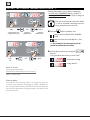
Connecting stacked appliances (MAXI.Link)
Connecting appliance with RJ45 cable
3
4
RJ45
6
RJ45
All ChefTop and BakerTop ovens are factory prepared
WR EH FRQQHFWHG WRJHWKHU RU WR DFFHVVRULHV SURYHU
KRRG EODVWFKLOOHU RVPRVLV V\VWHP HWF The accessories connect to the oven by means of RJ45 connectors located on the back of the ovens, which
2
automatically connect.
n Disconnect all appliances from the electricity mains.
o Remove the rear panel to access the power board.
p Use a cutter to make a vertical slit in one of the rubber caps on the panel behind the oven
1
q Thread one end of the RJ45 cable through the slot.
r Insert the end of the cable into the corresponding
5
IHPDOHFRQQHFWRURQWKHSRZHU3&%LWGRHVQRW
PDWWHUZKLFKRIWKHWKUHHFRQQHFWRUVLVXVHG
s Replace the protective cover and tighten the screws.
t Reconnect all the appliances to the electricity mains.
Follow the instructions of the accessory packing
for information on how to install and manage
them.
Setting ovens as “MASTER” or “CONTROLLED”
MASTER
RJ45
RJ45
RJ45
CONTROLLED
OVEN 1
English
When dealing with more than one UNOX oven, for
sake or practicality it is best to set one oven as main
0$67(5DQGWKHRWKHUVWRDPD[LPXPRIDVDX[LOLDU\&21752//('
All "CONTROLLED" ovens and connected add-ons
LHKRRGSURYHUUHYHUVHRVPRVLVNLWHWFVHH“Table
E”FDQEHPDQDJHGIURPWKH0$67(5RYHQFRQWURO
panel.
The EFFICIENT.Power technology cuts the baking station's power consumption of up to 33% by better exploiting distribution of electrical power.
7KHVWDQGDUGRYHQVDUHFRQILJXUHGDV´0$67(5µ
0DLQWDLQ WKH RYHQV LQGHSHQGHQW DOO 0$67(5
by not executing the following configuration and
by not connecting them with the RJ45 cable. The ovens
will not function if they are connected with the network
FDEOHZLWKRXWH[HFXWLQJWKHVHWWLQJSURFHGXUHPHVVDJe
´12$16µQRDQVZHURQWKHVFUHHQ
40
ChefTop™
BakerTop™
Table E
No.
appliances
BakerTop™ Range
Devices
No.
appliances
ChefTop™ Range
Devices
1
2
3
4
6
BakerTop™ Oven - MASTER
BakerTop™ Oven - CONTROLLED 1
BakerTop™ Oven - CONTROLLED 2
BakerTop™ Oven - CONTROLLED 3
Prover
1
2
3
4
5
7
Reverse osmosis system
6
8
Static oven - Deck oven
9
Hood
10
Ovex.NET
7
8
9
10
ChefTop™ Oven - MASTER
ChefTop™ Oven - CONTROLLED 1
ChefTop™ Oven - CONTROLLED 2
ChefTop™ Oven - CONTROLLED 3
Blast-chiller
Temperature maintainer
Slow cooking oven
Reverse osmosis system
Static oven
Hood
Ovex.NET
n
Disconnect
the RJ45 network cable that connects
WKH RYHQV VHH FKDSWHUConnecting appliance
with RJ45 cable at page 40 ,I WKLV LV WKH ILUVW
installation, the ovens are already independent.
o 6ZLWFK 21 WKH RYHQ WKDW ZLOO EH VHW DV ´&21752//('µ '2 127 LQLWLDWH DQ\ FRRNLQJ F\FOH
VXFKDVFRRNLQJXVHWKHFRQWUROSDQHOWRHQWHUWKH
hidden menu by simultaneously pressing and hold-
2
5 sec.
ing for 5 seconds the
buttons.
p
Press the
button once -> the number 10 is
highlighted on the time screen.
3
q
Repeatedly press the
button until calling the
"OU" parameter onto the screen.
x1
r
Repeatedly press the
button until the program
screen displays the number you wish to assign to the
"CONTROLLED" oven from which the settings are
PDGHVHH“Table E”
If connecting only 2 ovens, assign the setting OU2
to the "CONTROLLED" oven.
5
4
s
To
save the assigned setting hold and press the
button for 5 seconds until hearing the save
confirmation signal.
t
Press the
button to exit the hidden menu.
u
'LVFRQQHFW WKHSRZHU FDEOH IURPWKH´0$67(5µ
DQG´&21752//('µRYHQV
7
v
Connect the ovens with the RJ45 cable.
w
Simultaneously connect the oven plugs.
6
41
English
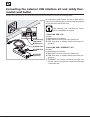
Connecting the external USB interface kit and safety thermostat reset button
Consult the instructions on the external peripherals and accessories to mount and manage these.
$Q RYHUKHDWLQJ UHVHW EXWWRQ $ DQG DQ 5- DWWDFKPHQWSRUWIRUVHUYLFLQJ%DUHVHULHVIHDWXUHVHTXLSSHG
on the right hand side of the oven.
7KH IROORZLQJ XVHU LQWHUIDFH NLWV 2YH[
1(7DUHDYDLODEOHRQUHTXHVW
“Unox.LINK USB” Kit:
Includes:
$2YHUKHDWLQJUHVHWEXWWRQ
$2YHUKHDWLQJ &5-&DEOHWRFRQQHFWWKHXVHULQWHUIDFHNLW
reset button
' 86% IODVK GULYH WR XSGDWH VRIWZDUH DQG ORDG SUR%5-SRUW
grammes.
&5-FDEOH
“Unox.LINK USB+ETHERNET” Kit
'86%IODVK Includes:
drive
$2YHUKHDWLQJUHVHWEXWWRQ
&5-&DEOHWRFRQQHFWWKHXVHULQWHUIDFHNLW
Ovex.NET
' 86% IODVK GULYH WR XSGDWH VRIWZDUH DQG ORDG SURRSWLRQDO
grammes.
((7+(51(7IRULQWHUQHWFRQQHFWLYLW\WKURXJKDFDble that exits the component compartment through
a cable pass-wall.
English
42
ChefTop™
BakerTop™
Examples of correct and incorrect installation
OK!
2c
m
OK!
OK!
180 cm
OK!
>5
OK!
0c
43
m
English
INSTRUCTIONS FOR THE USER
Contents
General appliance operating instructions _______________________________________________________45
Cooking advice ___________________________________________________________________________45
Loading and using the trolleys ________________________________________________________________46
Using the core probe ______________________________________________________________________47
´0$67(5µRYHQV´&21752//('µRYHQVDQGFRQQHFWHGDFFHVVRULHV ______________________________48
&22.,1*6<67(03ROORRQO\IRUWKH&KHI7RSUDQJH _________________________________________49
Use ____________________________________________________________________________________50
Basic notions __________________________________________________________________________51
MANUAL operation ____________________________________________________________________52
PROGRAMMED operation _______________________________________________________________57
Oven-user interface _______________________________________________________________________67
Routine maintenance ______________________________________________________________________72
Inactivity ________________________________________________________________________________76
End of life disposal _________________________________________________________________________76
After-sales assistance _______________________________________________________________________77
Certification______________________________________________________________________________78
Guarantee _______________________________________________________________________________78
English
44
ChefTop™
BakerTop™
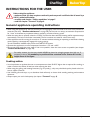
INSTRUCTIONS FOR THE USER
Before using the appliance:
- make sure that you have a system conformity and use permit certificate that is issued by a
UNOX authorised installer;
- carefully read chapter “Safety regulations“ at page 5
- read the chapter “Forward” at page 4.
General appliance operating instructions
:KHQXVLQJWKHDSSOLDQFHIRUWKHILUVWWLPHEHVXUHWRWKRURXJKO\FOHDQWKHLQVLGHRIWKHRYHQFDYLW\DQGWKHDFFHVVRULHVVHHFKDS “Routine maintenance” at page 72OHWWKHRYHQUXQHPSW\DWPD[LPXPWHPSHUDWXUH
for 1 hour to eliminate any unpleasant odours caused by protective factory grease.
:KHQWKHRYHQGRRULVRSHQHGXQOHVVWKH&22/IXQFWLRQKDVEHHQVHOHFWHGKHDWLQJDQGIDQRSHUDWLRQVWRSV
DXWRPDWLFDOO\7KHEXLOWLQIDQEUDNHLVDFWLYDWHG7KHIDQFRQWLQXHVWRURWDWHIRUDVKRUWWLPHRQO\
,IWKHDSSOLDQFHZDVOHIWUXQQLQJIRUPRUHWKDQPLQXWHVZLWKRXWVHOHFWLQJDQRSHUDWLQJRUDXWRPDWLFFOHDQLQJ
mode, stand-by is automatically engaged for energy savings.
To exit STAND-BY MODE simply touch the START/STOP button.
2SHUDWHWKHDSSOLDQFHDWDURRPWHPSHUDWXUHEHWZHHQ&DQG&
'RQRWVDOWIRRGLQVLGHWKHRYHQFDYLW\,IWKLVLVQRWSRVVLEOHFOHDQWKHRYHQDVVRRQDVSRVVLEOHVHHFKDSWHU
“Routine maintenance” at page 72
For safety reasons, the last tray should NEVER be placed at a height greater than 160 cm. If
necessary to do so, it is mandatory to post the sticker contained in the "Starter Kit" at the
height shown in the figure.
Cooking advice
,WLVDOZD\VEHWWHUWRSUHKHDWWKHRYHQWRDWHPSHUDWXUHDWOHDVW&KLJKHUWKDQLVUHTXLUHGIRUFRRNLQJLQ
order to reduce the effects of heat lost when opening the door.
:KHQXVLQJWKHJULOOLQJDQGURDVWLQJIXQFWLRQVHJIRUSRXOWU\DGULSWUD\VKRXOGDOZD\VEHSODFHGDWWKHERWtom to collect excess fat.
8VH 812; JULOOV DQG WUD\V WU\ WR GLVWULEXWH IRRG XQLIRUPO\ RQ WKHVH ZKLOH DYRLGLQJ VWDFNLQJ DQG H[FHVVLYH
quantities.
$OZD\VUHVSHFW\RXURYHQ
VORDGFDSDFLW\VHHFKDSWHU“Forward” at page 4
45
English
Trolley loading and use (
only free-standing trolley ovens)
Use only UNOX trolleys, trays and
grills.
/RDG WKH WUROOH\V ZLWKRXW RYHUORDGLQJ WKHP LW LV
normal for the trolley to be pushed downward and
lower in height, depending on how full the trays are.
7KHWUROOH\LVORDGHGLQWRWKHRYHQXVLQJWKHERWWRP
trolley guides.
Lock the trays into place when moving the trolley as
shown in the figure.
$OZD\V ORFN WKH IURQW ZKHHO EUDNHV LQWR SODFH DIWHU
putting loads into the oven cavity and each time these
are not to be moved.
%HH[WUHPHO\FDUHIXOZKHQPRYLQJEHFDXVHWKHWUD\V
may contain boiling fluids that may spill or the trolleys
PD\FDSVL]HIRUH[DPSOHLIPRYHGDFURVVXQHYHQRU
LQFOLQHGIORRUVRUWKURXJKGRRUV
English
46
ChefTop™
BakerTop™
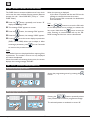
Core probe positioning
OK
During the cooking cycle, the probe detects the temperature at the "core" of the product: it reaches the temperature set by the user when the product is perfectly
cooked both on its surface and innermost portion.
The core probe must be poked deep into the food being cooked; make sure that the probe head reaches
the product's "core" - the innermost portion - without
piercing its way through. If the food you are cooking is
rather thin, insert the probe parallel to the oven tray.
When dealing with several foods, insert the probe into
the smallest product; take the product out of the oven
once it has reached the target temperature and move
the probe to the new smallest piece, thus starting the
F\FOH DQHZ VHH FKDSWHU “setting cooking DURA7,21WLPHZLWK&25(SUREHµ at page 53 .
The target core temperature depends on many
variables: nature of the food at hand, its size, etc.
The user's experience will allow him to determine the proper value.
MULTIPOINT PROBE: is a standard built-in feature
RI ´32:(5µ RYHQV ZLWK FRGH HQGLQJ LQ 3 HJ ;9C705EPLWPHDVXUHVWHPSHUDWXUHLQVHYHUDOSRLQWVRI
the needle and the screen output is an average of all
values taken.
SOUS-VIDE PROBE: measures temperature only at the
needle tip.
OK
Handle the probe with care because it is
extremely sharp and, after use, the needle reaches high temperatures.
Extract the probe from the food's core
before taking out the trays from the
oven, and set it on its external probe
KROGHU QHYHU OHDYH LW GDQJOLQJ LQVLGH
RXWVLGHWKHRYHQFDYLW\
Before extracting the tray check that the probe
cable is not in the way.
47
English
“MASTER” ovens, “CONTROLLED” ovens and connected accessories
If you own more than one UNOX appliance, we recommend that a specialised technician:
- connect all appliance with an RJ45 cable;
FRQILJXUH RQH RI WKH RYHQV DV PDLQ XQLW 0$67(5
DQG DOO RWKHU RYHQV XS WR XQLWV DV DX[LOLDU\ &21752//('
This makes it possible to manage the interconnected
"MASTER" oven, the "CONTROLLED" ovens and all
FRPSOHPHQWDU\DSSOLDQFHVHJSURYHUVVLPSO\E\DFWing on the control panel of the "MASTER" oven in lieu of
each appliance.
MASTER
RJ45
RJ45
RJ45
CONTROLLED
OVEN 1
The "MASTER" oven features direct use, while "CONTROLLED" ovens or complementary appliances are enbutton until the
gaged by repeatedly pressing the
FRUUHVSRQGLQJQXPEHUDSSHDUVRQWKHVFUHHQVHH“Table E”
Parameter configuration and use of the "CONTROLLED"
ovens is the same as for "MASTER" ovens.
$Q\FRQQHFWHGDFFHVVRULHVKRRGVDQGUHYHUVHRVPRVLV
NLWVDUHLQGHSHQGHQWO\PDQDJHGE\WKHRYHQFRQWrol system that automatically runs these accessories in relation
to actual needs.
7KHFRQWUROSDQHOVRIWKH&21752//('RYHQVDUHLGOHQRQRSHUDWLRQDOEHFDXVHWKH\DUHDOOFRQWUROOHG
E\WKH´0$67(5µRYHQFRQWUROSDQHO
Oven status can be changed from "CONTROLLED" to "MASTER" if need be: this operation must only be
performed by a specialised technician authorised by UNOX.
Table E
No.
appliances
BakerTop™ Range
Devices
No.
appliances
ChefTop™ Range
Devices
1
2
3
4
6
BakerTop™ Oven - MASTER
BakerTop™ Oven - CONTROLLED 1
BakerTop™ Oven - CONTROLLED 2
BakerTop™ Oven - CONTROLLED 3
Prover
1
2
3
4
5
7
Reverse osmosis system
6
8
Static oven - Deck oven
9
Hood
10
Ovex.NET
7
8
9
10
ChefTop™ Oven - MASTER
ChefTop™ Oven - CONTROLLED 1
ChefTop™ Oven - CONTROLLED 2
ChefTop™ Oven - CONTROLLED 3
Blast-chiller
Temperature maintainer
Slow cooking oven
Reverse osmosis system
Static oven
Hood
Ovex.NET
English
48
ChefTop™
COOKING SYSTEM Pollo
2
3
1
4
BakerTop™
(only for ChefTop™ ovens)
The range of ChefTop™ ovens, thanks to ADAPTIVE.Clima technology and an array of dedicated accessories,
makes it possible to cook chicken/fowl with significant savings in time, appliance cleaning and disposal of fats and oils.
n Rack PolloKROGVFKLFNHQ
Thanks to the Pollo, rack, the oven cavity space is
optimised to allow larger loads: the rack's design cooks
every chicken to perfection.
o Rack baskets Pollo KROGVFKLFNHQ
p Trolley Pollo
The trolley complements the Pollo rack baskets to
make transport to the deli counter much easier.
They come with fat-collecting trays mounted on the top
section.
q Cabinets Pollo*1*1
Special cabinets for chicken, come with:
- drain pipes controlled by a motorised valve for separate cooking-fat collection;
- airtight fat-collection tanks;
- cleaning detergent tank compartment.
49
English
Use
1
2
3
4
13
5
6
7
3UHVVUHSHDWHGO\WRVHOHFWWKH67(36WKHVFUHHQ
displays the STEP in use.
7KHVFUHHQGLVSOD\VWKHWLPHRUFRUHSURYHWHPperature set.
7KHVFUHHQGLVSOD\VWKHVHWFDYLW\WHPSHUDWXUHRU
Delta "t".
3UHVVWKHEXWWRQUHSHDWHGO\WRVHOHFWWKHSDUDPHWHUVWRVHWWHPSHUDWXUHFRRNLQJGXUDWLRQHWF
The active parameter is indicated by the blinking
corresponding icon:
8
12
9 10 11
6ZLWFKHVRQWKHDSSOLDQFHVVWDUWVVWRSVWKHFRRNing cycle.
The lit icon means that the oven is on.
3URJUDPPLQJVFUHHQ
3URJUDPPLQJEXWWRQIRUGHWDLOVVHHSDJH57
6DYHVVHWSURJUDPV
3URJUDPPLQJEXWWRQIRUGHWDLOVVHHSDJH57
0$;,/LQNControls the ovens and complementary appliances connected to the ovens: the screen
shows the number of appliances in use.
CLIMA.Lux - Repeatedly pressing the left/right butWRQVFRQWUROVVWHDPLQSXW67($03OXVRUKXPLGLW\H[WUDFWLRQIURPWKHFDYLW\'5<3OXV
cooking time shown on screen as hours: minutes
core probe temperature shown on screen as °C
cavity probe temperature shown on screen as °C
WHPSHUDWXUH'HOWD´WµGLIIHUHQFHEHWZHHQFDYLW\DQG
FRUHSUREHWHPSHUDWXUHVVKRZQRQVFUHHQDV&
Increases/decreases values shown on screen.
6HWVWKHDLUIORZVSHHGVKRZQRQVFUHHQ
The control panels are used by pressing the screen-printed keypad.
Press only with fingers and no other objects, such as knives, forks, etc...
This technology makes cleaning the control panel quick and easy, while guaranteeing maximum reliability and
durability and avoiding any type of mechanical shifting.
OK
English
50
ChefTop™
BakerTop™
Basic notions
The appliances can be used in MANUAL or PROGRAMMED mode.
The MANUAL mode implies that the following parameters for each cooking cycle are set by the user:
FRRNLQJWLPHRUFRUHWHPSHUDWXUHE\PHDQVRIFRUHSUREHWKHWZRSDUDPHWHUVUHFLSURFDOO\H[FOXGHHDFKRWKHU
RYHQFDYLW\WHPSHUDWXUHRU'HOWDW'HOWDWFDQEHVHWRQO\LIWKHFRUHSUREHLVXVHG
&/,0$/X[SHUFHQWDJHRIRYHQFDYLW\VWHDPLQSXWUHOHDVH67($03OXV'5<3OXV
- airflow speed.
The parameters set are not saved and must be entered during each successive use.
PROGRAMMED mode makes it possible to:
VDYHZLWKDXVHUJLYHQQDPHXSWROHWWHUVXSWRFRRNLQJF\FOHVSURJUDPPHVIRUXVHLQVXFFHVVLYHFRRNLQJ
sessions;
XVHVSHFLDOIXQFWLRQVFOHDQLQJ&22/HWF
- use pre-set cooking programmes.
Each cooking cycle comprises 10 steps:
- STEP 1LQLWLDOSUHKHDWLQJRQO\IRUSURJUDPPHGPRGH
- STEPS 2 ...10: up to 9 cooking steps, each characterized by different cooking parameters. Cooking does not
necessarily require all nine STEPS: set only those required.
The appliance automatically passes from one cooking phase to the next.
Ex. COOKING CYCLE
PREHEATING
10 min
60 min
STEP 1 150°C
STEP 2 200°C
speed 1
60% steam
speed 3
20% steam
STEP
3, 4, 5, 6, 7, 8, 9
not used
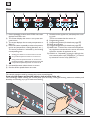
- When the oven is connected to the power supply, the control panel switches on automatically.
- Button functions
:
single repeated pressing -> increases/decreases the value one unit at a time;
held down -> increases/decreases the value rapidly.
- If no button is pressed within 15 minutes and there is no operating appliance connected to the control panel of
WKHVDPHRYHQHJSURYHUWKHHOHFWURQLFFRQWUROVJRLQWRVWDQGE\PRGHRQO\WKHVWDUWVWRSLED REMAINS
LIT. Simply press the START/STOP button to reactivate the electronic controls.
A reset button and an RJ45 port for servicing are series
features equipped on the right hand side of the oven.
A user interface kit is available at request:
contact UNOX for additional information.
reset button
RJ45 port
If the oven's sound signal is too low, UNOX recommends installing its Buzzer kit to increase
the volume; the kit can be installed at any moment by a specialised technician.
51
English
MANUAL mode
TIME CONFIGURATION
TEMPERATURE CONFIG.
SELECT
SELECT
DRY.Maxi
STEAM.Maxi
SELECT
2..9
TEMPERATURE CONFIG.
STEP
STEP
x2
CORE PROBE
CONFIGURATION
START/STOP
SELECT
DRY.Maxi
SELECT
DELTA “t”
CONFIGURATION
STEAM.Maxi
SELECT
x2
SELECT
Pressing the button moves from one STEP to the next; the current STEP is shown on the screen "1".
STEP
Pressing the button moves from one configuration parameter to the next; the parameter in use is displayed
by blinking icons, the set values are shown on their relative screens.
SELECT
cooking time shown on screen as hours: minutes
core probe temperature shown on screen as °C
cavity probe temperature shown on screen as °C
WHPSHUDWXUH'HOWD´WµGLIIHUHQFHEHWZHHQFDYLW\DQGFRUHSUREHWHPSHUDWXUHVVKRZQRQVFUHHQDV&
7KHSDUDPHWHUVGLVSOD\HGGHSHQGRQWKHFKRLFHV\RXPDNHIRUH[DPSOHWKH'HOWDWIXQFWLRQFDQQRWEH
XVHGIRUFRRNLQJLI67(3GXUDWLRQZDVVHWLQUHODWLRQWRWLPHLQVWHDGRIXVLQJWKHFRUHSUREH
PREHEATING
Preheating cannot be set in MANUAL mode.
STEP SELECTION
n Press the
button ;
o the number of the STEP in use appears on screen
XSWRDPD[LPXPRI67(36
English
52
ChefTop™
BakerTop™
SETTING COOKING DURATION7,0(:,7+&25(352%(
Cooking duration can be set by establishing:
- cooking TIME HJPLQRU
- the CORE TEMPERATURE measured by the probe
HJ&
- insert the probe into the smallest remaining product;
- close the door and press the
button: the oven
will propose the same previous core temperature.
The two values reciprocally exclude each
other: selecting the time in the same
STEP excludes the core temperature parameter and vice-versa. The following
can be set for a multi-STEP cooking process:
- all STEPS with TIME parameters;
- a single STEP managed by the CORE TEMPERA785( ZLWK WKH DELOLW\ WR UHSHDW LW DJDLQ VHH
point p
- starting STEPS with TIME parameters + last
67(3 ZKLFK FDQ EH UHSHDWHG FRQWUROOHG E\
CORE TEMPERATURE P.
Use the
buttons to make adjustments;
- re.start cooking by pressing the
START/STOP
button.
q TIME DEPENDANT COOKING STEP:
the STEP ends when the time set has elapsed, autoPDWLFDOO\PRYLQJRQWRWKHQH[WVWHSLIVHW
1
n Press the
button repeatedly until:
blinks to set the TIME
2
blinks to set the CORE TEMPERATURE
measured by the probe.
-> the parameter is active and can be adjusted only when the icon blinks.
o
´,1)µµ+2/'µ
0.00
CONTINUOUS
OPERATION
MINIMUM
DURATION
9.59
MAXIMUM
DURATION
SHWWKHGHVLUHGYDOXHWLPHRUFRUHWHPSHUDWXUH
buttons.
pressing the
The input values are shown on screen as hours.
PLQXWHVWLPHVHWWLQJRUSUREHVHWWLQJ
time configuration
1
2
probe configuration
x2
p
COOKING CYCLE SET IN RELATION TO CORE
TEMPERATURE MEASURED BY THE PROBE:
poke the probe into the smallest SURGXFW IRU
more information, see chapter “Core probe
positioning” at page 47.
The oven stops its cooking cycle and issues a
sound signal when reaching the set core temperature.
If you must re-start cooking, do as follows within
40 seconds of the sound signal:
- open the door;
- extract the probe from the cooked "pilot" product;
- take out all products similar in size to the "pilot"
from the oven, which are surely ready;
0°C
0.00
100°C
“INF”/”HOLD”&RQWLQXRXVPRGH
The oven is in continuous mode until the user manually
intervenes:
STEP 1!VHWWKHSDUDPHWHURQ´,1)µLQILQLWH
The temperature depends on the parameter set with
WKHGHGLFDWHGSDUDPHWHUVHHQH[WVHFWLRQ
STEP 2...9 !VHWWKH´+/'µ+2/'SDUDPHWHU
The temperature is maintained at 70°C and cannot be
modified.
53
English
SETTING THE COOKING TEMPERATURE OF DELTA "T"
Cooking temperature can be set by establishing:
- an oven cavity TEMPERATUREHJ&RU
- by using the'(/7$´tµIXQFWLRQRQO\LIXVLQJWKH
FRUHSUREH
1
The two values exclude each other: Delta
"t" will be excluded if selecting the oven
cavity parameter and vice-versa.
2
´3$8µ
OVEN PAUSED AND
FANS/RESISTORS OFF
0°C
MINIMUM
TEMPERATURE
260°C
n Press the
MINIMUM
TEMPERATURE
button repeatedly until:
blinks to set the OVEN CAVITY TEMPERATURE
EOLQNVWRVHWWKHYDOXHRIWKH'(/7$´WµIXQFtion.
-> the parameter is active and can be adjusted only when the icon blinks.
1
o
2
0°C
OFF
0°C
120°C
Set the desired value by pressing the
buttons.
The input values are shown on screen as°C.
temperature config.
config. Delta "t"
Delta "t" mode
Oven cavity temperature
–
Temperature measured by the core probe =
Delta "t" value to set
Start-up delay
To obtain an oven start-up delay or to pause the oven for
DFHUWDLQWLPHXVHIXOIRUOHDYHQLQJVHW´3$8µ3$86(RQ
the "cooking temperature" parameter and the pause duration
ZLWKWKHWLPHGHSHQGHQWFRRNLQJGXUDWLRQSDUDPHWHUVHH
SUHYLRXVVHFWLRQ
English
54
ChefTop™
BakerTop™
SETTING CLIMA LUX'5<0D[LDQG67($00D[L
1
3
2
The oven cavity internal climate setting is indicated
by the CLIMA LUX™ ellipse and is set using the
buttons.
DRY.Maxi
The 10 BLUE LEDs indicate the percentage of target
KXPLGLW\LQVLGHWKHRYHQFDYLW\67($0PD[L
STEAM.Maxi
DRY.Maxi™
The patented DRY.Maxi™ technology makes it possible
to quickly extract all the humidity from the oven cavity,
whether it was released by the products in the oven or
generated by the STEAM.Maxi™ system in a previous
cooking step.
STEAM.Maxi™
The patented STEAM.Maxi™ technology generate
steam inside the oven cavity at a starting temperature
of 48°C.
STEAM.Maxi™ introduces adjustable amounts of steam
in conjunction with various temperatures, allowing different types of cooking to take place:
6WHDPLQJRQO\VWHDP
0L[HGFRQYHFWLRQ²VWHDPDLUVWHDPFRRNLQJ
While cooking, the product naturally releases a certain
percentage of humidity: no steam will be produced by
the oven if the percentage matches the value set by the
user.
The 10 RED LEDs indicate the drying percentage inVLGHWKHRYHQFDYLW\67($00D[L
The two systems cannot be used together.
Setting the parameter is optional, if left unset,
the oven resorts to convection cooking.
n Repeatedly press the
EXWWRQXQWLOWKH´&/,0$
LUXµPHVVDJHEOLQNV-> the parameter is active and can be set only if the message blinks.
o To INPUT steamLQWRWKHRYHQFDYLW\67($0PD[L
press the
button repeatedly until setting
WKHGHVLUHGKXPLGLW\%/8(/('VIURPWR
7KH RYHQ DXWRPDWLFDOO\ HQJDJHV VWHDP
cooking mode for cooking temperatures below
130° and with a 100% humidity.
p
To RELEASE steamIURPWKHRYHQFDYLW\DRY.
PD[Lpress the
button repeatedly until setWLQJWKHGHVLUHGKXPLGLW\5('/('VIURP
WR
55
English
6(77,1*7+($,5)/2:63(('6$,50axi
The motor rotation speed and their work modes
can be set by pressing the
EXWWRQ ZLWKRXW
UHYHUVHURWDWLRQ6SHHGLVWKHGHIDXOWYDOXHZKHQ
the button is first pressed, while repeated pressing
sets the speed to 5, 4, 3, 2, 1 and P.
1
Pulsed mode
The pulsed mode switches off the motor as well as the
resistors when the set temperature has been reached.
The fan rotation direction is reversed each time the motor is switched on.
The set speed appears on screen "6":
VSHHGUSP:,7+287,19(56,21
VSHHGUSP:,7+287,19(56,21
VSHHGUSP:,7+287,19(56,21
VSHHGUSP:,7+,19(56,21
VSHHGUSP:,7+,19(56,21
VSHHGUSP:,7+,19(56,21
VSHHG3USP38/6('
6(/(&7,1*$1'6(77,1*7+(1(;767(36237,21$/
Cooking does not necessarily require all nine STEPS
available: set only those required.
To set step 2:
n press the
button;
oWKHQXPEHU´µ$33($56216&5((1.
The appliance automatically passes from one STEP to
the next.
6HWWKHYDULRXVSDUDPHWHUVGXUDWLRQWHPSHUDWXUH
HWFDVGHVFULEHGLQWKHSUHYLRXVVHFWLRQV,IQHFHVsary, select and set the following STEPS in the same
manner.
COOKING START/STOP/REPEAT - OVEN SHUT-DOWN
Having set the STEPS desired:
n
If using a cooking cycle that requires a core
probe, poke it into the product to cook; press
the
START/STOP
button to start the cooking cycle.
o
The sound emits a sound signal for 15 seconds
and the display blinks for about 45 seconds after
the oven ends its cooking cycle.
If at this time the following buttons are pressed:
Press and hold the
START/STOP
button for 2/3 seconds to interrupt
the cooking cycle in advance.
English
-> the oven starts-up again using the same
parameters as the previous cooking cycle;
-> the oven switches-off and the cooking
START/STOP
parameters are deleted.
56
ChefTop™
BakerTop™
PROGRAMMED Mode
ChefUNOX - BakerUNOX
LAST PROGRAM
+3 REGEN - STEAM - GRILL
FAKIRO GRILL - PAN FRY
MULTITIME - FAKIRO PIZZA
POLLO - COMBI BAKE
BAGUETTE - ROASTING
CRISPY ROAST - NIGHT ROAST
BRAISE
APPEARS ONLY IF A MANUAL
PROGRAMME WAS ENGAGED
RESTART
APPEARS ONLY IF A PROGRAMME
IS INTERRUPTED
ACM01
…
ACM20
PURE
PUMP LOADING
P01
COOL
POSITION OF
PROGRAMMES SAVED BY
THE USER
LONG WASHING
MED WASHING
SHORT WASHING
QUICK WASHING
SEMI AUTO WASHING
H2O WASHING
P99
CLEANING
PROGRAMME
....
POSITIONS OF
PROGRAMMES
SAVED BY THE
USER WITH ADAPTIVE.Clima technology
LAST PROGRAM 5(3($76$35(9,286&22.,1*&<&/(
This function fully repeats the last cooking cycle perIRUPHGRQO\LISHUIRUPHGLQSURJUDPPHGPRGH
n
At the end of the executed cooking cycle, press the
2
button -> the message LAST PROGRAM appears on screen "8".
1
o
Press the
starts.
START/STOP
button -> the last cycle executed
RESTART 5(680(6$1,17(55837('&22.,1*352&(66
If a cooking programme was interrupted in advance
H[HFXWHGERRWKLQPDQXDODQGSURJUDPPHGPRGHV
this function resumes it from the precise stop point
while maintaining the same parameters set.
2
n
Press the
1
EXWWRQXQWLOVFUHHQ´µdisplays the
message RESTART.
o
Press the
START/STOP
button: the last cooking cycle ex-
ecuted resume.
57
English
PURE
:$7(5),/7(5,1*6<67(06(77,1*6
The PURE function accesses a hidden menu from which
FDQEHVHWWKHZDWHUVRIWHQHUILOWHULQJV\VWHP5HYHUVH
RVPRVLV NLW ZLWK ´8QR[385(52µ SXPS RU ´8QR[
385(µILOWHUV
n
Press
the
EXWWRQ UHSHDWHGO\ XQWLO VFUHHQ ´µ
displays the message PURE.
o
The message "END" appears on screen.
p
Press the
button, the message "PIN" appears:
q
Press the
button, the message "HDR" appears.
r
Pressing
when the screen displays a parameter
When this warning is displayed:
$WKHILOWHULVUHSODFHGDQGWKHQHZ3,1RQWKH
package is entered to activate litre count;
% DQ LQFRUUHFW 3,1 LV HQWHUHG WKLV GHDFWLYDWHV
litre countdown.
PIN
buttons to write the PIN code
Use the
of the ILOWHU VKRZQ RQ LWV SDFNDJH WR DFWLYDWH WKH
button to save the
litre count. Hold down the
code. Entering an incorrect PIN calls up the "ERROR" message and the litre count is deactivated.
(1' 3,1 RU +'5 DOORZV \RX WR DGMXVW LW $IWHU
accessing a parameter, press
or wait 5 seconds
to return to the previous screen.
END
The residual litres are displayed before requiring filter
replacement. The number of litres are only displayed
and cannot be adjusted.
When the number of remaining litres is zero, the screen
displays the warning message "WPURE".
3!3&22.,1*352*5$00(6$9(
Access to the program menu
Access the programming menu by pressing the
button .
Assigning program position
Pressing the
buttons repeatedly selects
from positions P01 to P99 for programme storage.
The selected position is visualized on screen "8".
English
58
ChefTop™
BakerTop™
Assigning a name to a programme
n Press
.
o Use the
buttons to input the 1st let-
ter of the programme name. Press
3
1
again
buttons to select the
and use the
2nd letter. Repeat the same operation for all sucFHVVLYHOHWWHUVXSWRDPD[LPXPRIOHWWHUV
2
p To end letter input, press the
button and
check the name entered:
button to access the
if correct, press the
cooking parameters settings;
in incorrect, press the
input the letters.
button to correctly
Setting cooking parameters of a program
PREHEATING
n Press the
button repeatedly until the num-
ber´µ DSSHDUV RQ VFUHHQ ´µ DQG WKH PHVVDJH
´35(µRQVFUHHQ´µ
o
1
Pressing the
button repeatedly select
whether to set preheating in relation to:
the CAVITY TEMPERATURE
WKHIXQFWLRQ'(/7$´WµGLIIHUHQFHEHWZHHQ
preheating temperature and that of the 1st
FRRNLQJ67(3
-> only when the icon blinks is the parameter
active and adjustable.
p Press the
2
buttons to set the target
value.
3
DURATION, TEMPERATURE. CLIMATE, FAN SPEED
Set the following program parameters as fully exSODLQHGLQWKHFKDSWHU´0DQXDO2SHUDWLRQ
Saving the set program
Hold the
button until hearing the long "beep"
sound.
The program has now been saved.
59
English
RECALLING AND STARTING A SAVED PROGRAM
n Press the
button.
o
press
the
buttons until the target
program appears on screen "8".
p
start it by pressing the
START/STOP
button.
The oven beeps to signal cooking phase end.
2
1
Press the
button for 2/3 seconds to interrupt
START/STOP
the cooking cycle in advance.
When a saved cooking program is started,
the oven preheats automatically to the set
preheating temperature. Once preheating is over, the oven emits a sound signal
and the screen displays the values for the 1st cooking
STEP.
The cooking programme starts automatically after
putting the food into the oven and closing the door.
3
MODIFYING THE PARAMETERS OF A SET PROGRAM
n
Press the
button .
o
Use
buttons to call to screen the
program to modify.
p
Set the program parameters as fully explained in
WKHFKDSWHU´0DQXDO2SHUDWLRQ
q
Hold
2
the
button until hearing the long
"beep" sound. Now the modified parameters
have been saved.
1
3
English
60
ChefTop™
ChefUnox - BakerUnox
BakerTop™
35(6(7$8720$7,&352*5$00(6
The oven comes with a library of preset automatic
programmes for cooking specific foods VHH WDEOH RQ
IROORZLQJSDJH.
Select the various programmes to cook an endless variety of foods: several programmes allow adjustment of
different parameters to satisfy personal tastes.
1
nPress the
2
button.
o
Use the
button to select the desired pro-
gramme.
5(*(1
67($0
*5,//)$.,52
*5,//
3$1)5< 08/7,7,0(
FAKIRO PIZZA
3ROOR BLACK BAKE
%$*8(77(
52$67,1*
&5,63<52$67
1,*+752$67
%5$,6(
RQO\&KHI8QR[
RQO\&KHI8QR[
RQO\&KHI8QR[
RQO\&KHI8QR[
RQO\&KHI8QR[
RQO\&KHI8QR[
p
Follow
the instructions below if the selected
programme allows parameter adjustment.
ADJUSTING THE CORE TEMPERATURE / TIME
A
press the
button until to parameter to
adjust blinks;
RQO\&KHI8QR[
B
buttons; next move on to point q
RQO\%DFNHU8QR[
RQO\&KHI8QR[
RQO\&KHI8QR[
RQO\&KHI8QR[
RQO\&KHI8QR[
A
set the new target value pressing the
of the following page.
SETTING THE TIME ON 9 TIMERS
The preset STEAM, GRILL, FAKIRO GRILL, PAN
FRY and MULTITIME programmes run the oven in
continuous mode: this makes it possible to load different types of products that require different cooking times at any moment, and manage their preparation using 9 different timers. The function automatically updates the cooking times each time the door
is opened.
C
B
Press the
button until the clock icon
blinks.
D
Set the time on the first timer using the
buttons.
E
Press the
button followed by the
button: set the time on the second timer using
the
buttons and so on; next move
on to point q of the following page.
E
C
D
61
English
TEMPERATURE ADJUSTMENT - CLIMALUX - FAN SPEED
F
Press the
button until the temperature icon
G
Set preheating temperature using the
buttons.
H
Press the
EXWWRQXQWLOWKH´&OLPD/X[µPHVsage appears.
blinks.
F
G
I 6HW WKH GHVLUHG YDOXHV 67($0SOXV RU '5<SOXV
using the
q
buttons.
If you want the adjustments to be:
permanently saved into the selected programme
->press the
button for 5 seFRQGV VDYH
FRQILUPDWLRQLVZLWKDVRXQGVLJQDO
performed only for this cycle of cooking -> go
to point r.
H
I
rStart the programme by reading the detailed instructions:
MULTITIME
STEAM, GRILL, FAKIRO GRILL, PAN FRY
Press the
button-> preheating at the previSTART/STOP
ously set temperature starts.
The oven emits a sound signal when it reaches the
target temperature and the oven cavity light starts
to blink. Open the door, load the food and shut the
door: cooking starts with indefinite time duration
and with temperature, CLIMA LUX and fan speed
parameters previously set. When time has elapsed
on the first timer, the oven emits a sound signal and
the oven cavity light blinks: open the door and remove
the cooked food.
Shut the door: cooking continues. When time has
elapsed on the second timer, the oven emits another
sound signal and so on.
+3 REGEN, FAKIRO PIZZA, POLLO, BLACK
BAKE, BAGUETTE, ROASTING, CRISPY/
NIGHT ROASTING, BRAISE
Whenever the Fakiro Pizza programme is
used, remember to preheat the tray for at
least 5 minutes at a temperature exceeding
230°C.
Open the door, load the food, shut the door and
press the
starts.
English
button -> the selected programme
62
Whenever the Fakiro Grill programme is used, remember to preheat the tray for at least 5 minutes at a
temperature exceeding 230°C.
Open the door, load the food, shut the door
and press the
button ->the selected programme starts. When time has elapsed on the
first timer, the oven emits a sound signal and the
oven cavity light blinks: open the door and remove the cooked food.
Shut the door: cooking continues. When time
has elapsed on the second timer, the oven emits
another sound signal and so on.
7RLQWHUUXSWSURJUDPPHH[HFXWLRQLQDGYDQFHIRU
DOOSURJUDPPHVSUHVVWKH
START/STOP
button.
COOKING...
Cooking/Baking
ESSENTIAL
advised
ChefTop™
+3 REGEN
Regeneration
from 3°C
-
ChefTop™
STEAM
Steamed vegetables,
hard-boiled eggs,
steamed rice...
No Fry
Setting times on timers
1 to 9
ChefTop™
GRILL
Vegetables, meat and
fish from cold grill
Grill
Setting times on timers
1 to 9
ChefTop™
FAKIRO
GRILL
Vegetables, meat and
fish preheating the
grill in oven
FAKIRO Grill
Setting times on timers
1 to 9
ChefTop™
PAN FRY
Vegetables, meat,
pan-fried fish, bread
coated foods
Pan Fry
Setting times on timers
1 to 9
ChefTop™
MULTITIME
Several products
requiring different
FRRNLQJWLPHVVLPXOWDQHRXVFRRNLQJ
ChefTop™
ChefTop™
FAKIRO
PIZZA
Pizza and focaccia
bread
BakerTop™
BAGUETTE
Baguette and
similar bread
ROASTING
Roast meat
CRISPY
ROAST
Roast meat
with crust
NIGHT
ROAST
Roast meat
RYHUQLJKW
BRAISE
Braising and stewing
meats
NOTE
Core probe temperature
SUHVHW&
Preheat the tray for
at least 5 minutes at
a temperature above
230°C.
Setting time on timers 1 to 9
Temperature, CLIMA LUX,
fan speed
FAKIRO
Baked goods
-
PARAMETERS
ADJUSTABLE
Cooking time
Black.20 Black.20 Black.20 Black.20 Baguette Black Bake Chicken
BakerTop™
BLACK
BAKE
ChefTop™
Chicken, fowl, game
ChefTop™
®
ChefTop™
Pollo
ChefTop™
ChefTop™
ChefTop™
BakerTop™
PROGRAMMES
BakerTop™
Cooking time
SUHVHWPLQ
Preheat the tray for
at least 5 minutes at
a temperature above
230°C.
Cooking time
SUHVHWPLQ
Cooking time
SUHVHWPLQ
none
none
Core probe temperature
SUHVHW&
none
use of the core probe is COMPULSORY with this
programme
63
use of the core probe is OPTIONAL with this
programme
English
$&0!$&06$9,1*&22.,1*352*5$00(6:,7+$'$37,9(&/,0$
This technology allows the oven to constantly control all
FRRNLQJSDUDPHWHUVWHPSHUDWXUHUHDOKXPLGLW\OHYHOLQ
WKHFDYLW\HWF
Therefore, the oven is able to recognise the amount
of food loaded into it and consequentially adjusts the
parameters of the programme selected in function of
the actual load.
For example, given that each product releases steam
naturally, the amount of steam input into the cavity
67($00D[LYDULHVLQUHODWLRQWRRYHQORDGODUJHUWKH
ORDG!OHVVVWHDPSURGXFHGE\WKHRYHQ
The ADAPTIVE.Clima technology makes it possible to
save cooking cycles performed, including the effects of any manual adjustments made by the
XVHUHJRSHQLQJWKHRYHQGRRU
SAVING COOKING CYCLES
A &DUU\ RXW D ´3,/27µ SURJUDPPHG RU manual
cooking cycle, setting the most adequate parameters
for the products at issue.
Remember to insert the probe into the food’s core
even if not required by parameters set;
IRU PRUH GHtails see chapter “PROGRAMMED
Mode” at page 57 or chapter “MANUAL mode”
at page 52
B Check the results of the ´3,/27µFRRNLQJF\FOH
when cycle is complete:
IMPERFECT RESULTS-> DO NOT save the programme, repeat after adjusting cooking parameters
until obtaining desired result.
PERFECT RESULT-> save usingADAPTIVE.Clima
technology, see point C .
C Saving procedure:
n
press the
button;
o
repeatedly
press the
button until the
VFUHHQGLVSOD\VWKHQXPEHURIWKHPHPRU\IURP
$&0WR$&0RQZKLFKWKH´SLORWµFRRNLQJ
process will be saved;
p
press the
button;
q
use the
2
buttons to select the 1st letter of the name assigned; press the same buttons
again to select the 2nd letter; repeat for all successive letters;
1
r
after entering the name, press the
button;
s
press and hold the
button for 5 seconds to
VWRUHWKHSURJUDPLQWKHPHPRU\DIWHUVHFRQGVDFRQILUPDWLRQEHHSZLOOVRXQG
3
It is not possible to modify any parameters of a stored ADAPTIVE.
Clima programme.
4
ACCESSING SAVED PROGRAMMES
n press the
button;
o
select the ADAPTIVE.Clima programme desired
buttons;
by repeatedly pressing the
p
start the programme by pressing the
5
English
6
64
START/STOP
button.
ChefTop™
COOL
BakerTop™
29(1&$9,7<&22/,1*)81&7,21
The "COOL" function cools the oven cavity only by
running the fans.
The function can also be engaged while the door is
open to speed cooling.
The oven cavity temperature is displayed for the entire cooling duration.
3
1
2
n
Access the programming menu by pressing the
'XULQJ´&22/µPRGHRYHQFDYLW\FRROLQJ WKH DSSOLDQFH DOVR IXQFWLRQV ZKLOH
the door is open. Do not remove or
touch the protective fan casing, the fans
and the heating elements while the appliance is on and until complete cooling.
When the temperature drops below 50 °C,
VWRSWKH´&22/µIXQFWLRQDQGVZLWFKLWEDFN
on only if, after two minutes off, the cavity
temperature rises above 50 °C.
button .
o
Press the
button until "COOL" appears on
screen 8.
p
Press the
tion.
q
Press the
function.
START/STOP
START/STOP
button to start the "COOL" func-
button again to stop the "COOL"
WASHING :$6+,1*352*5$00(6AND PUMP LOADING/2$',1*'(7(5*(176
2
3
1
Rotor. KLEAN™ technology automatically/semi-automatically cleans the oven cavity by running pre-estabOLVKHG SURJUDPPHV WKDW FDQQRW EH DGMXVWHG VHH DOVR
chapter “CLEANING WITH ROTOR.KLEAN®“ at
page 73
n
Access the programming menu by pressing the
button.
o
Press the
buttons until screen "8"displays:
$ WKH PHVVDJH ´3803 /2$',1*µ: this program must
be engaged only after first oven use or after every
detergent tank replacement; it lasts about 25 seconds
and it loads the detergent from the tank while suction
tube. After pump loading, you MUST promptly
VWDUW D ZDVKLQJ F\FOH 6+2570('/21*
+2:$6+,1*VHHSRLQW%
65
% the list of available washing programmes:
- LONG WASHING
- MED WASHING
- SHORT WASHING
- QUICK WASHING
6(0,$872:$6+,1*RQO\IRUPDLQWHQDQFH
WHFKQLFLDQV
- H2O WASHING.
Consult the list on the following page for more information on these programmes.
p
Press the
button to start the desired proJUDPPH3803/2$',1*RU:$6+,1*
Do not open the oven door during
cleaning to avoid risks of injuries
caused by fan movement, hot steam
and aggressive action of chemical detergents used.
English
q
The washing programme is interrupted:
Programmes
Time *
$DWWKHHQGRIWKHWLPHOLVWHGLQWKHWDEOHQRQDGMXVWDEOH
QUICK
WASHING
30 min
->
%LQDGYDQFHE\SUHVVLQJ
indefinite override of the current washing program; the
H2O WASHING programme starts automatically and canQRWEHVWRSSHGPLQXWHGXUDWLRQ,IWKHUHLVDSRZHUIDLOure while the H20 WASHING programme is running, the
programme resumes from its interrupted point as soon as
power is restored;
SHORT
WASHING
39 min
MED
WASHING
58 min.
LONG
WASHING
1 hour
and 16
min.
& when the power supply to the appliance is down->
the current washing programme is momentarily interrupted; the programme automatically picks up from the
point where it left off when power is restored.
If power failure occurs during particular
ZDVKLQJPRPHQWVWKHPHVVDJH´$)µ
may appear on screen when power is
restored and the current washing programme is interrupted indefinitely.
In this case:
- eliminate the display message by cutting and restoring power to the appliance;
- manually reset the washing programme that will start
over.
H2O
WASHING
6 min.
cold water washing
automatic drying
** SEMI-AUTO
WASHING
10 min. +
18 min.
manual spray cleaner
automatic rinsing
automatic drying
PUMP LOADING
25 sec.
for loading detergent
'when the appliance has no water supply->
WKHDODUPPHVVDJH´$)µDSSHDUVRQ
screen and the current washing programme is interrupted indefinitely.
In this case:
- eliminate the display message by cutting and restoring power to the appliance;
- FKHFN WKH UHDVRQ IRU ZDWHU IDLOXUH HJ FXWRII YDOYH
FORVHGDQGUHVROYHLISRVVLEOH
water supply newly available: you must start a new
washing programme 48,&.6+2570('
/21*+2:$6+,1*, then use the oven as usual.
water supply still unavailable: the oven can still be used
while waiting for the water supply GR QRW XVH WKH
WASHING and STEAM.Maxi functions iQVLGHWKHFDYLW\
Prior to every use, the oven cavity MUST thoroughly
be washed several times to completely remove any
traces of residual detergent. The detergent comprises an extremely aggressive chemical substance; therefore, be extremely careful during
manual washing and wear adequate personal
SURWHFWLYHHTXLSPHQWJORYHVJODVVHVHWF
English
66
Description
quick hot washing
automatic rinsing
automatic drying
short hot washing
automatic rinsing
automatic drying
medium hot washing
automatic rinsing
automatic drying
long hot washing
automatic rinsing
automatic drying
* If the oven cavity temperature is:
- below 70°C -> the washing programme selected
starts immediately and lasts the amount of time
listed in the table;
- over 70°C -> a oven cavity cooling procedure
starts automatically WKH PHVVDJH ´,1)µ DSSHDUV
RQVFUHHQ.
The duration of the procedureYDULHVLWGHSHQGV
RQFDYLW\WHPSHUDWXUHDWFRROLQJVWDUW
The washing programme selected starts thereafter
and lasts the time listed in the table.
6(0,$872 :$6+,1* RQO\ IRU PDLQWHQDQFHWHFKQLFLDQV
If the oven cavity is particularly dirty, it is best to run
WKLV SURJUDPPH EHIRUH ZDVKLQJ 48,&.6+257
0('/21*:$6+,1*
c
The oven cavity is heated a few minutes when
the programme is engaged.
d
Open the oven door when a sound signal is
emitted and, while wearing personal protective
HTXLSPHQWHJJORYHVHWFPDQXDOO\VSUD\WKH
UNOX spray cleaner inside the oven cavity.
e
Shut the door again.
f
The oven remains in standby for 10 minutes to
allow the cleaner to act.
g
After this time has elapsed, rinsing and drying cycles start automatically, and last 18 minutes.
ChefTop™
BakerTop™
Oven-user interface
The ovens show any alarm/warning messages regarding
WKHRYHQRULQVWDOOHGSHULSKHUDOVSURYHUVRUKRRGVRQ
their display screens.
7KHZDUQLQJPHVVDJHVWARNINGVLJQDOPDOIXQFtions that nevertheless allow the appliance and peripherals to operate, though with a restricted set of
functions.
Pressing button
THE SCREEN.
clears the Warning list from
- The alarm messages $/$50 LGHQWLI\ VLWXDWLRQV
that fail to allow any appliance/peripheral operation
whatsoever, and therefore must be put into STOP
mode. If the alarm messages strictly refer to the peULSKHUDOVHJSURYHUVKRRGVHWFWKHRYHQFDQVWLOO
be used.
When there are several ALARM/WARNING MESSAGES, the user can scroll through these by repeatedly pressing
START/STOP.
Display
Description
Effect
Troubleshooting
AF - OVEN ALARMS
AF01
Motor thermal alarm
AF02
Safety thermostat alarm
AF03
Oven cavity alarm
AF04
Communications failure alarm
AF05
The oven stops any operating Contact the Customer Assistance
mode and blocks any screen display Service
Communications failure with gas configuration
board
AF06
Fume temperature in gas oven alarm
AF08
Motor tachometer
The oven stops any operating
mode and blocks any screen
display configuration. Turn the
oven's power on and off to
override the alarm and use the
DSSOLDQFHZLWKRXWXVHRIZDVKLQJ
Check the plumbing.
Once the water supply has been
restored, cut and restore power
to the oven and promptly start a
washing cycle.
AF09
No/little water supply during wash
AF010
Incorrect CRC alarm in EEPROM
for essential parameters
The oven stops any operating
No 230 V power supply to the gas mode and blocks any screen display Contact the Customer Assistance
Service
board
configuration
No 230 V power supply to the
chicken cabinet
AF011
AF012
67
English
Display
Description
Effect
Troubleshooting
WF - OVEN ALARM
WF01
Warning: cavity 1 probe
The oven continues to run using
the cavity 2 probe, therefore
temperature adjustments may be
less accurate
WF02
Warning: cavity 2 probe
The oven continues to run using
the cavity 1 probe, therefore
temperature adjustments may be
less accurate
WF03
Warning: core probe
The oven continues to run but the
core probe cannot be used for
cooking cycles
WF04
Warning motor tachometer:
alarm AF08 may be triggered
after this warning
The oven continues to run, no longer
stopping when the door is opened
and when put in reverse
WF05
Error: cooling fan
The oven continues to run but
proper internal component cooling
is no longer ensured.
WF06
Warning: gas temperature
board
The oven continues to run
WF08
Warning of Gas or Electric
oven setting
The oven continues to run but
is managed as an electric oven
WF10
Warning: EEPROM memory
indispensable parameters
The oven continues to run
ZLWKVHYHUDOOLPLWVEDVHGRQ
WKHSURSHUSDUDPHWHU
WF11
Warning: gas temperature board
The oven continues to run
WF12
Warning: thermocouple
temperature board
The oven continues to run
WF13
Warning: vacuum probe
The oven continues to run but
the external vacuum probe
cannot be used
WF15
Warning: communication
failure with thermocouple
board
The oven continues to run but
the external vacuum probe
cannot be used
WF17
Warning: multipoint probe on 1
or more measuring points
The oven continues to run
but the core temperature
measurement may be
inaccurate
WF18
Warning: chicken valve in liquid
setting, but no mechanical limit
detected
The drain valve may not
reverse position, thus no
longer ensuring proper oven
fluid drainage.
English
68
Contact
the
Assistance Service
Customer
ChefTop™
Display
Description
BakerTop™
Effect
Troubleshooting
The static oven stops all operating
cycles and blocks any display
screen configuration
Contact the Customer Assistance
Service
Effect
Troubleshooting
The static oven stops all operating
cycles and blocks any display
screen configuration
Contact the Customer Assistance
Service
Effect
Troubleshooting
AS - STATIC OVEN ALARM
AS01
Bottom thermostat safety alarm
AS02
Ceiling thermostat safety alarm
AS03
Oven dektop communications
alarm
Display
Description
AD - VIDEO BOARD PE1705 ALARM
AD01
EEPROM 12C Alarm
AD02
12C Capacitive touchscreen alarm
AD03
SPI screen communication alarm
AD04
Communications failure alarm
Display
Description
WD - VIDEO BOARD PE1705 WARNING
WPURE
Number of residual litres supplied
by Unox.Pure filter at zero
The WPURE message appears
when the oven detects UNOX.
PURE filter depletion
WD10
Error in EEPROM CRC for
parameters that can be used for
default or recipes
The oven may show anomalies
during setting.
Display
Description
Effect
Contact the Customer Assistance
Service
Troubleshooting
AC - HOOD ALARM
AC01
Communications failure alarm
Motor and smoke hood
disengaged
AC10
Incorrect CRC alarm in EEPROM
for essential parameters
Motor and smoke hood
disengaged
Display
Description
Effect
Contact the Customer Assistance
Service
Troubleshooting
WC - HOOD WARNING
WC01
Smoke detector failure
Smoke hood solenoid valve
does not open when a smoke
temperature probe is missing
WC02
Error of temperature board
The hood continues to run
WC03
Smoke detector 2 failure
One of the two smoke hoods fails
to engage.
WC04
Delta T cooling between probes
too low
Little or no smoke evacuation in
the steam condenser
WC10
Error in EEPROM CRC for
parameters that can be used as
default values
7KHKRRGFRQWLQXHVWRUXQEXW
with several limits based on the
SURSHUSDUDPHWHU
69
Contact the Customer Assistance
Service
English
Display
Description
Effect
Troubleshooting
AL - PROVER ALARM
AL01
Cavity probe alarm
AL02
Communications failure alarm
AL10
Incorrect CRC alarm in EEPROM
for essential parameters
Display
Description
The prover stops any operating
cycle and stops any successive
display screen settings
Effect
Contact the Customer Assistance
Service
Troubleshooting
WL - PROVER WARNING
WL01
Error humidity probe
WL02
Error of temperature board
WL03
Error of resistor compartment
probe
WL10
Error in EEPROM CRC for
parameters that can be used as
default values
Display
Description
The prover continues to run but
the automatic humidity regulation
feature cannot be engaged
Contact the Customer Assistance
Service
The prover continues to run
Effect
Troubleshooting
AM - TEMPERATURE MAINTAINER ALARM
AM01
Cavity probe alarm
AM02
Communications failure alarm
AM03
Safety thermostat alarm
The temperature maintainer stops
all operating cycles and blocks
any successive display screen
configuration
AM10
Incorrect CRC alarm in EEPROM
for essential parameters
ì
Display
Description
Effect
Contact the Customer Assistance
Service
Troubleshooting
WM - TEMPERATURE MAINTAINER WARNING
WM01
Error with motor tachometer
WM02
Error of temperature board
WM03
Error core probe
The maintainer continues to run
but core probe processes cannot
be activated.
WM10
Error in EEPROM CRC for
parameters that can be used as
default values
The maintainer continues to run
English
The maintainer continues to run
70
Contact the Customer Assistance
Service
ChefTop™
Display
Description
Effect
BakerTop™
Troubleshooting
AO - REVERSE OSMOSIS ALARM
AO01
Pressure gauge alarm: excessive
pressure
AO02
Low pressure alarm
AO03
Effect
Display
Reverse osmosis stops all water
treatment cycles
Contact the Customer Assistance
Service
Communications failure alarm
Description
Effect
Troubleshooting
WO - REVERSE OSMOSIS WARNING
WO01
Osmosis filter to be replaced
WO02
Intake filters obstructed
WO03
NTC temperature above
threshold
Display
Description
Osmosis is active
Contact the Customer Assistance
Service
Effect
Troubleshooting
AA - BLAST CHILLER ALARM
AA01
Cavity probe alarm
AA02
Safety pressure gauge alarm
AA03
Communications failure alarm
AA10
Incorrect CRC alarm in EEPROM
for essential parameters
The blast chiller stops all operating
cycles and blocks any successive
display screen configuration
Contact the Customer Assistance
Service
Effect
Display
Description
Effect
Troubleshooting
WA - BLAST CHILLER WARNING
WA01
Error of temperature board
WA02
Dirty filter
The blast chiller continues to run
WA03
Core probe error
The blast chiller continues to run
but core probe processes cannot
be activated.
WA10
Error in EEPROM CRC for
parameters that can be used as
default values
The blast chiller continues to run
71
Contact the Customer Assistance
Service
English
Routine maintenance
Any routine maintenance procedure must be performed:
- after disconnecting the appliance from the power, water and gas supplies(
ONLY FOR GAS
OVENS);
DIWHUKDYLQJSXWRQWKHSURSHUSHUVRQDOSURWHFWLRQHTXLSPHQWLHJORYHVHWF
Clean the oven cavity daily to maintain proper levels of hygiene and to keep the stainless steel inside the oven
cavity from getting ruined or corroding. Clean the oven daily even if the appliance is used exclusively with humid
KHDWVWHDP
When cleaning any component or accessory NEVER use:
- abrasive or powder detergents;
DJJUHVVLYH RU FRUURVLYH GHWHUJHQWV LH K\GURFKORULFPXULDWLF RU VROIXULF DFLG &DXWLRQ 1HYHU XVH
these substances also when cleaning the appliance
substructure and floors;
DEUDVLYHRUVKDUSWRROVLHDEUDVLYHVSRQJHVVFUDSHUVVWHHOEULVWOHGEUXVKHVHWF
- high pressure cleaners with hot water sprays or high
pressure steam jets.
External steel structures, oven cavity seal, core probe
Wait for the surfaces to cool off.
Use only a soft cleaning cloth dampened with a little
soap and water. Rinse and dry completely.
In alternative, only use detergents recommended by
UNOX; other products may cause damage thereby invalidating the guarantee. Read the instructions provided
by the detergent producer for their use.
Plastic surfaces and control panels
Use only a very soft cleaning cloth and a spare amount of detergent for cleaning delicate surfaces.
English
72
ChefTop™
BakerTop™
Internal part of the oven cavity
Failure to clean the oven cavity daily as hereafter described can make the accumulated fatty
substances or food residues inside the cavity catch fire - danger of fire!
CLEANING WITH ROTOR.KLEAN®
7KHRYHQVFRPHHTXLSSHGZLWKRQHWZRLPSHOOHUVIRU
cleaning the oven cavity.
Follow the procedure below for correct cleaning:
UNOX.Det&Rinse
PDNH VXUH WKDW WKH GHWHUJHQW WDQN LV QRW HPSW\ DQG LV
properly fastened to the ring nut of the supply tube.
We recommend using only UNOX.Det&Rinse
cleaner by UNOX.
UNOX.Det&Rinse is the UNOX solution that offers
both detergent and rinse aid in a single product, otherwise sold separately. The working principle of UNOX.
Det&Rinse combines the degreasing action of detergents and the power of rinse aid to obtain the best results during oven washing and rinsing.
se
et
.D
OX
in
&R
UN
e
.Pur
OX
From
UN
re
.Pu
OX
To
UN
R IN
TE
WA
1
2
only for free-standing trolley ovens:
load the trolley into the cavity and lock it in place with
the front wheel brakes.
0DNH VXUH WKDW WKH GRRU LV FRPSOHWHO\ FORVHG DQG
that the drain pipe is free of obstructions or caps.
Do not open the oven door during
cleaning to avoid risks of injuries caused
by fan movement, hot steam and aggressive action of chemical detergents
used.
6HHFKDSWHU“:$6+,1*ZDVKLQJSURJUDPPHV
$1' 3803 /2$',1* ORDGLQJ GHWHUJHQWV” at
page 65 and run the programme best suited to your
needs.
REMOVING THE IMPELLER
2
The impeller can be removed to make cleaning the oven
cavity easier. Do this by pushing upward and unscrewing it
counter-clockwise.
Clean with soapy water or descaler by following the instructions provided by the detergent manufacturer.
Replace after cleaning by performing the steps in reverse order.
1
73
English
WASHING BY HAND
1
2
Follow the procedure below for cleaning the oven cavity:
- switch on the oven and set the temperature to 55°C
DQGVWHDP67($00D[LWR
- run the oven for 10 minutes;
- wait for the surfaces to cool off and clean with a soft
cleaning cloth;
- rinse completely to remove all residues.
Remove the side grill holder to make cleaning easier as
shown in the figure.
Clean the grill holders with soapy water or specific cleaners; do not clean inside the dishwasher.
3
4
55°C
5
6
7
STEAM. Maxi 100%
1
English
2
74
ChefTop™
BakerTop™
If the appliance is not permanently connected
to a drainage system, the conical plug that
seals the drain pipe must be removed before
starting any washing cycles.
Replace the plug after this procedure.
OK
Inside and outside oven door window glass
Wait for the windows to cool off.
Use only a soft cleaning cloth dampened with a
little soap and water or specific glass cleaners.
Rinse and dry completely.
If more thorough cleaning is necessary, the inside window can be opened by following the
indications shown in the figure.
1
2
3
3
OK
Mod. XCV 055
Mod. XCV 105
1
3
2
75
English
only for gas ovens
Appliances that evacuate exhaust gas through a flue must have qualified installer inspect
it periodically in compliance with the laws in force in the country of installation.
Request written documentation of the inspection.
Inactivity
Follow the precautions below during inactivity:
- disconnect the power, water and gas supplies to the appliance (
ONLY FOR GAS OVENS);
- we recommend rubbing a soft cloth lightly doused with mineral oil on all stainless steel surfaces;
- keep the appliance door slightly ajar.
At first reuse:
FOHDQWKHDSSOLDQFHDQGLWVDFFHVVRULHVWKRURXJKO\VHHFKDSWHU“Routine maintenance” at page 72;
- restore the power, water and gas supplies to the appliance (
ONLY FOR GAS OVENS);
- inspect the appliance before using it;
- switch on the appliance at minimum temperature for 50 minutes without any food inside of it.
It is best to have an authorized customer assistance service perform maintenance and
inspection on the appliance at least once a year to ensure top working and safety conditions.
Disposal
,QSXUVXLWRIDUWLFOH1RRIODZ-XO\1R´,PSOHPHQWDWLRQRIWKH'LUHFWLYHV(&
EC and 2003/108/EC.
The product must undergo separate collection processes and cannot be disposed of as general waste
when reaching end of life; keep in mind that illegal or incorrect product disposal incurs penalties as put
forth by the current laws in force.
$OODSSOLDQFHVDUHPDGHZLWKUHF\FODEOHPHWDOVVWDLQOHVVVWHHOLURQDOXPLQLXPJDOYDQL]HGVWHHOFRSSHUHWFIRUPRUHWKDQRIRYHUDOOZHLJKWGLVSRVDORIWKHSURGXFWDWWKHHQGRILWVOLIHPXVWEH
performed by electronic and electrical waste recycling centres, or the appliance must be returned to the dealer
when buying a new equivalent product, on a one to one basis.
Render the appliance for disposal useless by removing the power cable and any compartment or cavity closure
ODWFKZKHUHSUHVHQWWRDYRLGSRVVLEOHHQWUDSPHQWRISHUVRQV
Contact the local waste disposal centre for additional information.
English
76
ChefTop™
BakerTop™
After-sales assistance
In case of any malfunctions, disconnect the appliance from its power and water supply. Consult the solutions
proposed in the “Table F”.
If the solution is not listed in the table, contact a UNOX
authorized technical customer service. Provide the following information:
- the date of purchase;
- the appliance data on the serial plate;
DQ\DODUPPHVVDJHVVKRZQRQWKHGLVSOD\VFUHHQVHH
chapter “Oven-user interface” at page 67
XBC
LI2293A0 - Printed: 06-2012
Subject to technical changes.
Manufacturer's information:
UNOX S.p.A.
via dell’Artigianato, 28/30
9LJRGDU]HUH3',WDO\
Tel +39 049 8657511 - Fax +39 049 57555
- Italy
e (PD) .555
negh 86.57
Cado 049
0 - +39
. - 3501- Fax: x.com
22 .511 .uno
X S.p.A
rana,86.57 www
UNO
Majo049
.com
Via 39
Tel.:+ unox
info@
Table F
Malfunction
Possible cause
The oven is completely - No mains power.
switched off.
- Appliance out of order.
No steam is produced inside the oven cavity.
Possible solution
Problem solution
Make sure the appli- Contact the Customer Asance is connected to sistance Service.
the electricity mains.
- Open water inlet.
- Water inlet closed.
- Appliance
plumbed - Make sure the appliance is plumbed into
into the water mains
the water mains or
or the tank incorrectly.
the tank correctly.
- No water in the tank - Fill the tank with water.
LIZDWHULVWDNHQIURP
WKHWDQN
- Water supply filter - Clean the filter.
clogged with impurities.
Contact the Customer Assistance Service.
After the time has been Door open or not shut Make sure the door is Contact the Customer Asset and the START / STOP properly.
shut.
sistance Service.
button pressed, the oven
does not start.
Water escapes from the - Seal is filthy.
- Clean the seal using a Contact the Customer Assistance Service.
seal while the door is shut. - Seal is damaged.
damp cloth.
- The handle mecha- - Contact a specialised
nism is loose.
technician to request
the necessary repair
work.
77
English
Certification
EU declaration of conformity for electrical appliances
Manufacturer: UNOX S.p.A.
Address: Via Dell’Artigianato, 28/30 - I - 35010 - Vigodarzere, Padua, Italy
Declares, under its own responsibility, that the product
ChefTop ™ e BakerTop™ – Serie 5E
is compliant to the Machine Directive 2006/42/EC through the following standards:
EN 60335-2-42: 2003 + A1: 2008
EN 60335-1: 2002 + A1: 2004 + A11: 2004 + A2: 2006 + A12: 2006 + A13: 2008
EN 62233: 2008
and to the Electromagnetic Compatibility Directive 2004/108/EC through the following standards:
EN 55014-1: 2006 + A1: 2009
EN 55014-2: 1997 + A1: 2001 + A2: 2008
EN 61000-3-2: 2006 + A1: 2009 + A2: 2009
EN 61000-3-3: 2008
EN61000-3-11: 2000
EN61000-3-12: 2005
EN 61000-6-2: 2005
EN 61000-6-3: 2007
and Directive 2009/142/EC on gas appliances:
EN203-1
EN203-2-2
Guarantee
Installation of the UNOX product must be performed by an Authorized UNOX Assistance Service. The installation date and appliance model must be documented by the end purchaser, by means of written confirmation or
an installation invoice issued by the dealer or the Authorised UNOX Customer Assistance Service, otherwise this
guarantee will not be valid;
The UNOX guarantee covers all malfunctions objectively linked to production defects. The guarantee excludes
damage due to transport, poor product storage or maintenance or incorrect product use. Also excluded is damage due to installation not conform to the technical specifications provided by Unox and linked to the environment
of use, such as, for example, unclean and aggressive water supply, low quality gas supply, or electrical supply failing
to respect nominal voltage and power ratings.
The guarantee also excludes any damage due to power surges or tampering by unauthorized or incompetent
persons. The guarantee is also invalidated for damage to the appliance by lime scale deposits. In addition, the guarantee does not cover consumables, such as: seals, light bulbs, glass panels, decorative parts and parts consumed
during use.
Guarantee rights will also be invalidated in the event of damage arising as a result of incorrect installation, or installation which has not been carried out by an Authorised Customer Assistance Service.
English
78
OVENS PLANET ®
International B.V.
Groot Mijdrechtstraat 42
Postbus 32
3640 AA Mijdrecht
Tel. +31 (0)297-282341 - Fax. +31(0)297-287405
BAKERTOP-CHEFTOP nl ma 2012
www.emga.com
[email protected]
www.unox.com