1
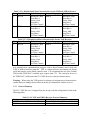
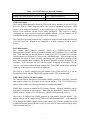
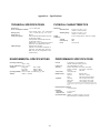
SV12 GPS Receiver
User’s Manual
CTI06-117
May 2006
Prepared by:
Coleman Technologies, Inc.
20 North Orange Avenue, Suite 300
Orlando, Florida 32801
(407) 481-8600
Table of Contents
1.0
PREFACE ......................................................................................................................................... 1
2.0
SV12 GPS RECEIVER OVERVIEW............................................................................................. 1
2.1
2.1.1
2.2
2.3
2.4
3.0
Interface Protocols ..................................................................................................................... 2
SV12 GPS Serial Port Interface ............................................................................................. 3
Antenna....................................................................................................................................... 3
Power.......................................................................................................................................... 4
Hardware Setup.......................................................................................................................... 4
INTEGRATION OF THE SV12 GPS RECEIVER ...................................................................... 5
3.1
Hardware Integration................................................................................................................. 5
3.1.1
Power Requirement ................................................................................................................ 5
3.1.2
Pulse Per Second.................................................................................................................... 6
3.1.3
Mounting ................................................................................................................................ 6
3.2
Software Interface ...................................................................................................................... 7
3.2.1
Start-up ................................................................................................................................... 7
3.2.2
Communicating with the SV12 GPS Receiver ........................................................................ 7
3.2.3
Protocol Summary .................................................................................................................. 8
APPENDIX A – SPECIFICATIONS ..................................................................................................... A-1
1.0
PREFACE
The Global Positioning System (GPS) is a satellite based navigation system operated and
maintained by the U.S. Government. The GPS consists of a constellation of 24 satellites
providing world-wide, 24 hour, three dimensional (3-D) coverage. GPS applications
include military, surveying, marine, land, aviation, and vehicle navigation. GPS is the
most accurate technology available for vehicle navigation/location.
Since GPS is a satellite based system, it is immune to the limitations of land-based
systems such as Loran. Loran is limited in coverage and can be adversely affected by
weather. In addition, the accuracy of Loran is significantly worse than GPS. By
computing the distance to GPS satellites orbiting the earth, a GPS receiver can calculate
an accurate position. To determine a 2-D position calculation (latitude/longitude), 3 GPS
satellites must be in range. A 3-D position calculation (which includes altitude), requires
a minimum of 4 GPS satellites to be in range. GPS receivers can also provide precise
time, speed and course measurements.
Differential GPS (DGPS) is a form of GPS navigation which provides even greater
accuracy than standard GPS. Differential GPS requires error corrections transmitted
from a GPS receiver placed in a known location, referred to as a reference station. The
reference station calculates the error in the satellite range data and outputs corrections for
use by other GPS receivers. These GPS receivers are designated as mobile units and can
be dispersed as far as 100 KM form the reference station. Differential GPS eliminates
virtually all the measurement error in the satellite ranges and enables a highly accurate
position calculation. The SV12 GPS receiver is differential-ready for applications
requiring DGPS accuracy.
The SV12 GPS Receiver is an upgrade to CTI’s SV8 GPS Receiver (which was a
replacement for the Trimble SVeeEight Plus GPS Receiver). The SV12 GPS Receiver is
manufactured by Coleman Technologies, Inc., located at 20 North Orange Avenue, Suite
300; Orlando, FL 32801.
2.0
SV12 GPS RECEIVER OVERVIEW
The SV12 GPS Receiver delivers an unmatched level of performance for your GPS
applications. The device uses the Trimble’s Lassen® iQ12-channel GPS module. The
iQ GPS module has improved immunity to in-band jammers over it’s predecessors and is
designed to track weak signals improving position availability in environments with
obscured coverage.
The SV12 GPS Receiver includes a complete 12-channel parallel tracking GPS receiver
designed to operate with the L1 frequency, Standard Position Service, Coarse Acquisition
code, using Trimble custom integrated circuits. The receiver is housed in a rugged metal
enclosure especially suited for plug and play applications. The SV12 GPS receiver
1
acquires a position fix with minimal delay after power cycling. The following
information is necessary to help decrease the time to track satellites after power-up and is
stored in RAM when backup power is provided:
•
•
•
•
Almanac
Ephemeris
Real-time clock
Last position
User settings, including port parameters and receiver processing options, can be stored in
non-volatile electrically erasable (EEPROM) that does not require power.
The SV12 GPS Receiver has two independently configurable serial I/O communication
ports. The dual data I/O port characteristics and other options are user programmable
and can be stored in non-volatile memory.
Warning – When customizing port assignments or characteristics, confirm that your
changes do not affect the ability to communicate with the receiver.
2.1
Interface Protocols
The SV12 GPS Receiver operates using either of three protocols – Trimble Standard
Interface Protocol (TSIP), Trimble ASCII Interface Protocol (TAIP) and NMEA 0183
(Version 3.0). The SV12 GPS Receiver also supports RTCM SC-104 for DGPS. The
factory default settings for the different factory default configurations are listed in Table
2.1-1 and Table 2.1-2.
Table 2.1-1 TSIP and NMEA Receiver Interface Protocols
Port
Port 1
Port 2
Setting
NMEA 0183 out/RTCM SC-104 V2.1 in
TSIP bi-directional
Table 2.1-2 TAIP Receiver Interface Protocols
Port
Port 1
Port 2
Setting
NMEA 0183 out/ RTCM SC-104 V2.1 in
TAIP bi-directional
TSIP
TSIP is a binary packet protocol that allows the system designer maximum configuration
control over the GPS receiver for optimum performance in any number of applications.
TSIP supports over 40 commands and their associated response packets for use in
configuring the SV12 GPS Receiver to meet user requirements.
2
TAIP
TAIP is an easy-to-use ASCII protocol developed by Trimble for vehicle tracking. The
user can set up polling schemes and mark GPS messages with unique identifiers. The
TAIP messages and output rates are user selectable and can be configured to operate on
either Port 1 or Port 2.
NMEA 0183
NMEA 0183 is an industry standard protocol common to marine applications. NMEA
provides direct compatibility with other NMEA-capable devices such as chart plotters,
radars, etc. The SV12 GPS Receiver supports most NMEA messages for GPS
navigation. NMEA messages and output rates can be user selected as required.
2.1.1
SV12 GPS Serial Port Interface
The GPS Receiver is a DCE (Data Communication Equipment) device. To connect to a
host computer, or DTE (Date Terminal Equipment) device, use a straight through cable.
To connect a Differential Radio (DCE device) to the receiver (DCE device) use a crossover cable or null modem cable. See Table 2.1.1-1
Table 2.1.1-1 Serial Port Pin-outs
Port 2
Description
Pin
NC
1
TX
2
RX
3
NC
4
GND
5
NC
6
NC
7
NC
8
PPS Out
9
Port 1
Pin
1
2
3
4
5
6
7
8
9
Description
NC
TX
RX
NC
GND
NC
NC
NC
PPS Out
The PPS signal is an open collector interface on pin 9 of Ports 1 and 2. The polarity of
the PPS signal is an inverted, 10 µs negative going pulse with the falling edge
synchronized to UTC. One can use a 10 K pull-up resistor to pull-up the PPS.
2.2
Antenna
The GPS antenna receives the GPS satellite signal and passes them to the receiver.
Because the GPS signals are spread spectrum signals in the 1575 MHz range and do not
penetrate conductive or opaque surfaces, the GPS antenna must be located outdoors with
a clear view of the sky. The SV12 GPS Receiver requires an active antenna. The
received GPS signals are very low power, approximately 140 dB, at the surface of the
3
earth. Trimble’s active antennas include a preamplifier that filters and amplifies the GPS
signals before delivery to the receiver.
There are two GPS antennas offered by Coleman Technologies, Inc. (1) magnetic mount
antenna and (2) bullet antenna. Equivalent antennas are available through 3rd party
vendors, for example Tessco at www.tessco.com. One needs to choose an active antenna
which is either a 3v, 3.3v or 3/5v antenna.
Warning – When magnetic-mount or permanent-mount GPS antennas are installed on a
metal surface for prolonged periods, care must be taken to insulate the antennas to
prevent galvanic corrosion.
2.3
Power
The SV12 GPS Receiver is designed to be plug-and-play. The receiver requires +9 to
+32 VDC. Power can be supplied to the SV12 GPS Receiver using the DC power cable.
The power cable is terminated at one end with a 3-pin plastic connector which mates with
the power connector on the metal enclosure. The un-terminated end of the cable provides
connection to a DC power supply. Connect the red power lead to a source of DC positive
+9 to +32 VDC, and connect the black power lead to ground. This connection supplies
power to both the receiver and the antenna. The combined power consumption of the
receiver and antenna is 25mA at 12V. The yellow wire can be used for battery backup to
keep the RAM memory alive and real-time clock functioning after main power is
removed (quicker time to first fix). This circuit requires 3.0 to 12 VDC and draws 20 µA
at 3.3 VDC at 20o C
Note - For compliance with CE conducted emissions requirements when using the DC
power cable, the receiver must be bonded to a ground plane.
2.4
Hardware Setup
The SV12 GPS Receiver supports TSIP, TAIP and NMEA protocols. Port 2 is usually
used for TSIP or TAIP I/O and Port 1 is used to input RTCM SC-104 corrections and
output NMEA messages.
To setup the SV12 GPS Receiver do the following:
1. For TSIP or TAIP protocols, connect one end of the 9-pin serial interface cable to
Port 2 (or Port 1 to view NMEA data) of the receiver. Connect the other end of
the cable to COM1 or COM2 on a PC. A 9-pin-to-25 pin adapter may be required
for the serial interface connection to a PC, if the PC has a 25-pin communication
port.
4
2. Connect the antenna cable to the receiver. Push the connector onto the MCX
connector on the receiver. To remove the antenna cable, pull the antenna
connector off of the MCX connector.
3. Place the antenna so that it has a clear view of the sky.
4. Using the DC power cable, connect to the 3-pin power connector on the receiver.
Connect the terminated end of the power cable to the power connector on the
receiver. Connect the red lead to the DC positive voltage (+9 to +32 VDC) and
black lead to the DC ground. The yellow wire is used for battery backup.
5. Switch on the DC power source.
3.0
INTEGRATION OF THE SV12 GPS RECEIVER
The integration of the SV12 GPS Receiver is provided below in two main sections:
Hardware Integration and Software Interface.
3.1
Hardware Integration
This section describes the instruction for physically connecting the receiver to the
antenna, the host processor, and the power source. Additionally, mounting instructions
are provided.
3.1.1
Power Requirement
The SV12 GPS Receiver requires 9-32 VDC. The SV12 draws less current than its
predecessor, the SV8 GPS Receiver.
The receiver does not require any special power up or down sequencing. Power is
supplied through the 3-pin Conxall connector.
The SV12 GPS receiver provides an input for battery back-up (BBU) power to keep the
receiver’s RAM memory alive and to power the real-time clock when the receiver’s
prime power is turned off. RAM memory stores the GPS almanac, ephemeris, and last
position.
User configuration data, including port parameters and receiver processing options, can
be stored in non-volatile EEROM which does not require back-up power. This is done
by issuing appropriate TSIP or TAIP commands. Though not required, using battery
back-up (BBU) can reduce the time to first fix significantly. (~10 seconds typical when
ephemeris is available). The BBU is attached using the yellow wire on the 3-wire power
connector.
5
Note – 3.0 V is the minimum allowable voltage for battery backup. When the power
output drops below 3.0 V, the real-time clock may not operate over the specified full
temperature range and this can significantly extend the time to first fix.
Power requirements are listed in Table 3.1.1-1
Signal
Battery Backup
Ground
VCC
3.1.2
Table 3.1.1-1 Power Requirements
Voltage
Current
+3.0 to 12
0 µA with prime power; 20 µA @ 3.3 V, 25oC
without prime power
0
+9 to 32
25mA typ @ 12V
Pulse Per Second
A ten microsecond wide, open collector negative going pulse synchronized UTC is
available on Pin 9 or ports 1 and 2. This pulse is issued once per second with the falling
edge of the pulse synchronized with UTC. The falling edge of the pulse is typically less
than 20 nanoseconds.
The timing accuracy is +/- 50 nanoseconds and is available only when the valid position
fixes are being reported. Repeatability checks of 10 sets of 100 second samples taken
over a period of 20 minutes showed an average variation of approximately 100
nanoseconds (not allowing for SA).
3.1.3
Mounting
The SV12 GPS Receiver is packaged in an anodized aluminum casing. When mounting,
consider vibrations. If the vibration is within the design specifications, then the receiver
can be hard-mounted. If not, select a mount that dampens the vibration enough to bring
the receiver back into specification.
For mounting, utilize metal screws through the four provided screw holes incorporated
into the enclosure. Select a screw length which extends a safe distance beyond the
mounting surface and secure these screws with nuts and lock washers. CTI recommends
that you use four number 8 pin-head machine screws.
6
3.2
Software Interface
This section describes the SV12 GPS Receiver software interface, the start-up
characteristics for the different interface protocols, a description of the receiver operating
modes, and a brief description of the interface protocols.
3.2.1
Start-up
When connected to an external GPS, the SV12 GPS Receiver contains all the circuitry
necessary to automatically acquire GPS satellite signals, track up to 12 GPS satellites,
and compute location, speed, heading, and time. The receiver automatically begins to
search for and track GPS satellite signals at power-up.
The performance of the GPS receiver at power-on is determined largely by the
availability and accuracy of the satellite ephemeris data and the availability of a GPS
system almanac.
The first time the receiver is powered-up, it is searching for satellites from a cold start
(no almanac). While the receiver begins to compute position solutions within the first
two minutes, the receiver must continuously track satellites for approximately 15 minutes
to develop a complete almanac. The initialization process should not be interrupted.
With a complete almanac and back-up power, the time to first fix can typically be
shortened to less than 45 seconds. The receiver responds to commands almost
immediately after power-up.
3.2.2
Communicating with the SV12 GPS Receiver
The SV12 GPS Receiver supports three message protocols: TSIP, TAIP, and NMEA. A
summary of the protocols are discussed below.
Communications with the SV12 GPS Receiver is through two RS-232 serial ports.
port characteristics can be changed to accommodate your application requirements.
parameters are stored in a non-volatile, electrically erasable ROM (EEROM) that
not require backup power. The following tables list the default characteristics for
port.
7
The
Port
does
each
Table 3.2.3-1 Default Serial Port Characteristics for the TSIP and NMEA Receiver
Port Input Protocol Default Setup
Output Language
Default Setup
NMEA
Baud Rate: 4800
1
RTCM
Baud Rate: 4800
Data Bits: 8
Data Bits: 8
Parity: None
Parity: None
Stop Bits: 1
Stop Bits: 1
No Flow Control
No Flow Control
TSIP
Baud Rate: 9600
2
TSIP
Baud Rate: 9600
Data Bits: 8
Data Bits: 8
Parity: Odd
Parity: Odd
Stop Bits: 1
Stop Bits: 1
No Flow Control
No Flow Control
Table 3.2.3-3 Default Serial Port Characteristics for the TAIP Receiver
Port Input Protocol Default Setup
Output Language
Default Setup
NMEA
Baud Rate: 4800
1
RTCM
Baud Rate: 4800
Data Bits: 8
Data Bits: 8
Parity: None
Parity: None
Stop Bits: 1
Stop Bits: 1
No Flow Control
No Flow Control
TAIP
Baud Rate: 4800
2
TAIP
Baud Rate: 4800
Data Bits: 8
Data Bits: 8
Parity: None
Parity: None
Stop Bits: 1
Stop Bits: 1
No Flow Control
No Flow Control
Any standard serial communications program, such as HyperTerminal, can be used with
TAIP or NMEA interface protocols. TSIP is a binary protocol and outputs raw binary
serial data onto the screen which cannot be read. CTI recommends the use of the Trimble
TSIP toolkit (TSIPCHAT) available upon request from CTI. The serial port drivers in
the TSIPCHAT Toolkit match the SV12 GPS Receiver serial port characteristics.
Warning – When using the TSIP protocol to change port assignments or characteristics,
confirm that your changes do not affect the ability to communicate with the receiver.
3.2.3
Protocol Summary
The SV12 GPS Receiver is shipped from the factory with the configurations listed in the
following tables:
Table 3.2.4-1 TSIP and NMEA Receiver Protocol Summary
Setting
Default
NMEA 0183 out/RTCM SC-104 V2.1 In
Port 1: 4800 baud none-8-1
TSIP bi-directional
Port 2: 9600 baud odd-8-1
8
Table 3.2.4-3 TAIP Receiver Protocol Summary
Setting
Default
NMEA 0183 out/RTCM SC-104 V2.1 In
Port 1: 4800 baud none-8-1
TAIP bi-directional
Port 2: 4800 baud none-8-1
TSIP Data Output
The Trimble Standard Interface Protocol (TSIP) is the native language for the SV12 GPS
Receiver. TSIP is a binary language with a wide variety of commands and reports. TSIP
reports can be output automatically, or they can be output as responses to queries. The
format of the automatic reports can be easily configured. The receiver is factory
configured for single precision Latitude-Longitude-Altitude. Report formats can be
modified and position and velocity formats can be customized.
The TSIPCHAT program permits using a computer keyboard to send the Request Packets
to the GPS receiver. Responses are displayed on a DOS computer screen in ASCII
format.
TAIP Data Output
The Trimble ASCII Interface Protocol (TAIP) is a Trimble-specified digital
communications interface based on printable/readable ASCII characters over a serial data
link. TAIP interface provides the means to configure the SV12 GPS Receiver to output
various sentences in response to a query or on a scheduled basis. TAIP messages can be
scheduled for output at a user specified rate starting on a given epoch from top of the
hour. For communication robustness, the protocol optimally supports checksums of all
messages. It also provides the user with the option of tagging all messages with the
receiver’s user specified identification number (ID). This greatly enhances the functional
capability of the receiver in a network environment.
The receiver is factory configured by part number to the TAIP protocol, or it can be
configured to TAIP with the TSIPCHAT program and the TSIP command 0xBC.
NMEA 0183 (Version 3.0) Data Output
The National Marine Electronics Association (NMEA) protocol is an industry standard
data protocol which was developed for the marine industry. The SV12 GPS Receiver
adheres to the NMEA 0183 data specification as published by NMEA.
NMEA data is output in standard ASCII sentence formats. Message identifiers signify
what data is contained in each sentence. Data fields are separated by commas within the
NMEA sentence. In the SV12 GPS Receiver, NMEA is an output only protocol.
The receiver is shipped with NMEA protocol by part number from the factory. The
NMEA settings can be changed using TSIPCHAT and command 0xBC. TSIP command
0x7A changes the NMEA output sentences and output rates. The new settings are saved
to BBRAM (battery backup RAM) or they can be saved to non-volatile memory using
TSIP command 0x8E-26.
9
Note – Although the SV12 GPS Receiver supports the seven NMEA sentences that
contain GPS information, the factory default setting for the receiver only outputs the
GGA and VTG data strings. To change the output interval or sentence output, use TSIP
Command Packet 0x7A.
10
Appendix A – Specifications
PHYSICAL CHARACTERISTICS
TECHNICAL SPECIFICATIONS
Dimensions
Prime Power
+9 to +32 VDC input
Metal Enclosure
Power consumption (nominal)
25 mA, 30 mW, at 12V, +25oC, with antenna
Mounting flange
Back-up power
+3.0 to +12 VDC (20 µa @ +3.3V, +25oC)
Serial ports (2)
RS-232
Weight
I/O Protocol options
TSIP (Trimble Standard Interface Protocol)
Connectors
@ 9600 baud, 8-Odd-1
Antenna
TAIP (Trimble ASCII Interface Protocol)
Serial data (2)
@ 4800 baud, 8-None-1
Power
NMEA 0183 v3.0 @ @4800 baud, 8-None-1
RTCM SC-104 @ 4800 baud, 8-None-1
NMEA messages
Standard: GGA and VTG
Optional: User-selectable combination of;
GGA, GLL, VTG, ZDA, GSV, GSA and
RMC; user can store configuration in nonvolatile memory
4.03” D x 4.97” W x 1.1” H
(102mm x 127mm x 28mm)
4.03” D x 6.81” W x 1.1” H
(102mm x 173mm x 2mm)
0.57 lb. (0.26kg) (board + enclosure + flange)
MCX
DB9
3-pin Conxall
ENVIRONMENTAL SPECIFICATIONS
PERFORMANCE SPECIFICATIONS
Operating temperature
-40oC to +85oC
Storage temperature -55oC to +100oC
Vibration
0.008 g2/Hz
5Hz to 20Hz
20Hz to 100Hz
0.05 g2/Hz
3bD/octave
100Hz to 900Hz
Operating humidity 5% to 95% R.H., non-condensing, @ +60oC
Altitude
-400m to +18,000m
General
Update rate
Accuracy
1 PPS (static)
DGPD accuracy
Acquistion
L1 frequency, C/A code (SPS), 12channel continuous tracking receiver
1 Hz (TSIP,NMEA, or TAIP)
Position - Horizontal: <5m (50%), <8m (90%)
Position - Altitude: <10m (50%), <16m (90%)
Velocity:
0.06 m/sec
±50 nanoseconds
Positoon:
2m CEP (50%)
Velocity:
0.05 m/sec (1 sigma)
Time:
±500 nanoseconds (nominal)
Cold start:
<50 sec (50%) <84 sec 90%
Warm start:
<38 sec (50%) <42 sec 90%
Hot start:
<10 sec (50%) <13 sec 90%
Cold start requires no initialzation. Warm start implies last position, time
and almanac are saved by back-up power. Hot start implies ephemeris also
saved.
Racquistion after signal loss
<2 seconds (90%)
Dynamics
Accerlation
4g (39.2 m/sec2)
Motional Jerk
20 m/sec2
Operational Limits Altitude <18,000m or velocity <515 m/sec
Either limit may be executed but not both
A-1