1
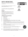
OWNER’S MANUAL
BASS AMPLIFIER HEAD
LWA 1000
Fami l y O w n ed
◊
So la r P o we r e d
◊
S ustainably Manufactur ed in a Gr een E nvir onment
INDEX
Introduction3
Safety Instructions
4
Product Features
7
Optional Accessories
7
Front Panel Description
8
Rear Panel Description
9
Channel Selector Footswitch
10
Setup Guide
10
Troubleshooting
11
INTRODUCTION
Congratulations! on the purchase of your new Warwick LWA 1000 bass amplifier head. Two channels of true 1000 Watt power in a
compact, lightweight design is now in your hands.
Our considerations in the design of this product were multifold and our objectives were to provide:
• An affordable amplifier for the discerning musician.
• A gigging amplifier for the seasoned professional.
• Transparent and noise-free sonic performance.
• Ultra-portable, lightweight design.
Here is a short description of the underlying design concepts:
CLASS A OPERATION
Class A amplifiers are typically more linear and as such are less complex than other amplifier classes. In Class A amplifiers, the
amplification circuitry is designed so that it is always conducting electrical current. This means that the active elements are always on,
thus avoiding the problem of crossover distortion.
LOW-Z CIRCUITRY
Thermal noise is a critical design issue when it comes to audio electronics. By lowering the impedance of components inside an
electronic circuit, the overall thermal noise is substantially reduced. The Low-Z circuitry inside all of our amplifiers makes it possible to
achieve consistently noise-free operation.
We hope you enjoy your new bass amplifier as much as we enjoyed designing it!
3
SAFETY INSTRUCTIONS
Caution: To reduce the risk of electrical shock, do not remove the
cover as there are no user serviceable parts inside. Refer servicing
to qualified personnel.
This symbol, wherever it appears, alerts you to the presence of noninsulated
dangerous voltage inside the enclosure - voltage that may
be sufficient to constitute risk of shock.
This symbol, wherever it appears, alerts you to important operating
and maintenance instructions in the accompanying literature. Read
the manual.
WARNING!
This amplifier is capable of producing high sound pressure levels.
Continued exposure to these high sound pressure levels can cause
permanent and irreversible hearing damage. Ear protection is
recommended if unit is operated at high volume for long period of
time. If you experience any hearing loss or ringing in the ears you
should consult a doctor.
IMPORTANT SAFETY INSTRUCTIONS
1. 2. 3. 4. 5. 6. 7. 8. 9. 10. 11. Read these instructions
Keep these instructions
Heed all warnings
Follow all instructions
Do not use this apparatus near water
Clean only with dry cloth.
Do not block any ventilation openings. Install in accordance with the manufacture’s instructions.
Do not install near any heat sources such as radiators, heat registers, stoves, or other apparatus
(including amplifiers) that produce heat.
Do not defeat the safety purpose of the polarized or grounding plug. A polarized plug has two blades with one wider
than the other. A grounding plug has two blades and a third grounding prong. The wide blade or the third prong is
provided for your safety. If the provided plug does not fit into your outlet, consult an electrician for replacement of the
obsolete outlet.
Protect the power cord from being walked on or pinched particularly at the plugs, convenience receptacles, and at the
point where they exit from the apparatus.
Only use attachments/accessories specified by the manufacturer.
12. Use only with the cart, stand, tripod, bracket, or table specified by the manufacturer, or sold with
the apparatus. When a cart or rack is used, use caution when moving the cart/apparatus
combination to avoid injury from tip-over.
13. 14. Unplug the apparatus during lightning storms or when unused for long periods of time.
Refer all servicing to qualified personnel. Servicing is required when the apparatus has been damaged in any way,
such as power supply cord or plug is damaged, liquid has been spilled or objects have fallen into the apparatus has
been exposed to rain or moisture, does not operate normally, or has been dropped.
4
15. WARNING: To reduce the risk of fire or electric shock, do not expose this apparatus to rain or moisture. The apparatus shall not be exposed to dripping or splashing and that objects filled with liquids, such as vases,
shall not be placed on apparatus.
16. Never set the amplifier on a support that might give out under its weight.
17. WARNING: The mains plug used as disconnect device, the disconnect device shall remain readily operable.
18. Protective earthing terminal. The apparatus should be connected to a mains socket outlet with a
protective earthing connection.
19. Replace fuse with rated value, never bridge defective fuses. Before changing fuse disconnect power cable from unit!
20. Correct Disposal of this product. This marking indicates that this product should not be disposed
with other household wastes throughout the EU. To prevent possible harm to the environment or human health from uncontrolled waste disposal, recycle it responsibly to promote the sustainable reuse of material
resources. To return your used device, please use the return and collection systems or contact the retailer where the product was purchased. They can take this product for environmental safe recycling.
PRODUCT SHOULD BE SERVICED BY QUALIFIED PERSONNEL WHEN:
1. 2. 3. 4. Unit has been dropped or the enclosure is damaged.
Mains switch has been damaged
Objects or liquids have penetrated the unit.
Unit does not operate normally and troubleshooting (last chapter of this manual) does not help.
5
PROTECTIVE CIRCUITS
Your new Warwick LWA 1000 amplifier is equipped with a multitude of protective circuits to prevent it from malfunction under
inappropriate operating conditions.
Over current protection:
All amplifier channels are over current protected on outputs. Current clipping is engaged when the amplifier channels exceed its
specified peak current output. This can be seen as the output voltage of the amplifier being clipped. If the current output of an amplifier
channel exceeds its specified peak current output for a longer period of time e.g. in case of a short circuit of the output, the amplifier will
be disabled (Muted) for 1000ms and automatically restart.
DC current protection:
A built-in DC protection circuit will attenuate any DC signals on the power amplifier input, produced by a signal containing a DC signal.
In case of a permanent DC on the output of the amplifier, the amplifier will latch and power must be removed for the product to restart.
Over-/under voltage protection:
Power supply over- and undervoltage protection is implemented, which means that the power supply will enter a protection mode when
the operational off-line voltage exceeds or drops below the specified upper and lower operational off-line AC voltages. However
exceeding 265VAC for a longer period of time might damage the power supply primary side permanently.
HF protection:
A high frequency protection is implemented in order to protect the power amplifier module filter components from overload. The high
frequency protection algorithm has been implemented to protect the amplifier from excessive HF signals on the amplifier outputs.
Excessive Temperature:
This circuit protects the power stages from malfunction by switching the device off if the temperature-regulated fan cooling proves to be
insufficient and temperature of the unit is too high.
6
PRODUCT FEATURES
ARTICLE NUMBERS:
W A LWA 1000 SILVER
W A LWA 1000 SIL UK
• 1000 Watt Bass Amplifier Head.
• Lightweight and ultra-portable.
• Class A preamp circuitry.
• Class D power amp section.
• Two independent channels.
• Channels can be selected remotely with footswitch.
• Separate Input Gain control for each channel.
ARTICLE NUMBERS:
W A LWA 1000 BLACK
• Mute function (separate for each channel)
W A LWA 1000 BLK UK
• 4-Band equalizer (separate for each channel)
• Adjustable Compressor with bypass function (separate for each channel)
• Compression knob simultaneously controls the compression amount and make-up gain.
• Stereo auxiliary input jack for connecting MP3 player, CD player etc.
• Integrated stereo headphone amplifier.
• Serial FX Loop.
• Tuner Output
• Line Output
• Balanced DI output with Pre/Post and Ground Lift switches.
• Dual purpose ¼” jack and lockable speaker connector.
• Internal temperature regulating fan control circuitry.
• Dimensions (W/H/D): 270mm x 98mm x 146mm (10.6” x 3.86” x 5.75”)
• Weight: 2.75 kg (5.95 lbs.)
OPTIONAL ACCESSORIES
LWA 1000 Rackmount Ears:
LWA 1000 Amp Bag:
• Available in Black or Silver
• 280mm x 120mm x 230mm (11.1” x 4.7” x 9.6”)
• With strap
ARTICLE NUMBERS:
W A LWA 1000 RE BLACK
W A LWA 1000 RE SILVER
ARTICLE NUMBER:
7
W A RB 23011 B
FRONT PANEL DESCRIPTION
3 4
2
5
7
6
CHANNEL 1
0
0
OFF
0
9
8
11 12
COMPRESSOR
0
OFF
1
AMP CLIP
0
INPUT
12
GAIN
ON
MUTE
-12
+12
BASS
-12
+12
LOW MID
-12
+12
HIGH MID
-12
+12
TREBLE
0
12
0N
AUX IN
AMOUNT
10
CHANNEL 2
0
OFF
0
0
COMPRESSOR
0
0
OFF
12
VOLUME
13
0
INPUT
12
GAIN
ON
MUTE
-12
+12
BASS
-12
+12
LOW MID
-12
+12
HIGH MID
-12
+12
TREBLE
0
12
AMOUNT
ON
HEADPHONES
LWA 1000
(Indicators 1-9 shown only for Channel 1, Channel 2 has exactly identical corresponding functions)
1. Input jack – Accepts a standard 6.25mm (1/4”) audio jack for connecting active or passive basses using a properly
shielded cable.
2. Gain – Adjusts the input gain of the preamp stage.
3. Signal Level LED – This LED, when green indicates that the input is at least 0dBU (0.77V RMS). When red, it
indicates clipping in the preamp stage. If the preamp is clipping, turn down the gain on some of the preamp stage
controls (Gain, EQ or Compression as applicable).
4. Mute ON/OFF – Engaging this switch will mute all outputs except for the Tuner Out. When not engaged, the
respective channel is activated.
5. Mute LED – Indicates Mute status. Red indicates channel is muted (Mute ON), green indicates channel is active (Mute OFF).
6. Equalizer – 4-Band EQ provides +/- 12 dB of gain for each band.
• BASS – 100Hz
• LOW MID – 800Hz
• HIGH MID – 3kHz
• TREBLE – 10kHz
7. Compression Amount – This knob controls, as the name says, the amount of compression by providing simultaneous control
over compression threshold and make-up gain. The Compression knob, whenever engaged should be used in conjunction with
the Gain control. Settings of up to about 12 o’ clock add a subtle compression. This setting will only compress the most
aggressive transients in your signal. Setting the knob at around 3 o’ clock yields a heavy compression effect, with more
make-up gain. We designed our compressor to be completely transparent and to not color the signal in any way.
8. Compressor LED – When green, this indicates that the compressor is engaged. When orange, it indicates that the signal is getting compressed.
9. Compression ON/OFF – This switch engages/bypasses the compressor circuit.
10. Volume – This knob controls the master volume.
11. Amp Clip LED – This LED indicates that the output from the power amp module is clipping. If the power amp is clipping, turn down the master volume.
12. AUX IN jack – Accepts a standard 3.5mm (1/8”) audio jack (stereo compatible) for connecting an auxiliary sound source. This can be used for connecting a CD, tape or MP3 player for practicing, rehearsing or for connecting another preamp into the system.
13. HEADPHONES – Accepts a standard 3.5mm (1/8”) audio jack for connecting headphones.
8
BACK PANEL DESCRIPTION
4
6
5
2
8
9
7
DE93670540
4003874
10
1
3
1.
Mains Power ON/OFF switch – For your safety remember to connect the power cord from the mains outlet to the
amplifier BEFORE turning this switch on. Conversely, when disconnecting the amp, turn the switch OFF first, then
disconnect cord from the outlet and finally disconnect the power cord from the amp.
2.
AC Mains IN – Power socket for connecting the amplifier to the mains power supply.
3.
Integrated Fuse compartment – To replace the fuse, first disconnect power cord from the AC Mains IN socket.
Use a small screwdriver to remove the fuse compartment. Caution! Replace only with indicated size and type
(T5AL 250V). Using a fuse with different rating than specified can cause damage to your amplifier.
4.
TUNER OUT – Accepts a standard 6.25mm (1/4”) audio jack for connecting amplifier to a tuner unit.
Signal remains active on this output even when the Mute switch is ON, allowing for silent tuning.
5.
EFFECT SEND/RETURN – Accepts standard 6.25mm (1/4”) audio jacks for connecting an effects chain.
The FX Loop in the LWA 1000 is of the serial type.
6.
LINE OUT – Accepts a standard 6.25mm (1/4”) audio jack. This is an unbalanced line level output for connecting
to external devices (auxiliary power amplifier, FOH mixer etc.)
7.
DI OUT – Balanced XLR output for connecting the amplifier to a PA or a mixing desk in the studio.
8.
PRE/POST – This switch affects the DI OUT signal. In the ”PRE” position the DI OUT is fed the signal before the EQ, Compressor and FX Loop from the preamp. Conversely, in the ”POST” position, the DI OUT is fed the signal after
the EQ, Compressor and FX Loop.
9.
GROUND LIFT – This switch internally disconnects the chassis ground connection (essentially the Earth terminal of AC Mains) from the ground pin of the DI OUT. Use this functionality when there is excessive hum, possibly
caused by a ground loop or bad earthing.
10.
SPEAKER OUT – Lockable speaker connector for connecting the amplifier to a speaker cabinet.
The minimum load for the amplifier is 4 ohm.
9
CHANNEL SELECTOR FOOTSWITCH
2
1
3
ARTICLE NUMBER:
W A LWA 2S
Your new LWA 1000 comes with a footswitch and supplied cable provided for remote channel switching capability. Simply route your
instrument through the footswitch and connect to one of the amplifier inputs.
1.
IN – Use a standard guitar cable to connect your instrument to the input of this unit.
2.
OUT – Use the provided TRS (tip-ring-sleeve) cable for connecting the footswitch to any of the two inputs on the LWA 1000. Any of the two inputs can be used to connect the footswitch and the choice of input does not affect
functionality in any way.
3.
CH1/CH2 – Toggles between Channel 1 and Channel 2.
SETUP GUIDE
1.
Unpacking – Carefully unpack unit from the carton box.
2.
Powering up – Ensure the mains power switch is in ”OFF” position and then connect the supplied power cord from the AC Mains socket of the amplifier to the mains power outlet. Now flip the power switch on the amplifier to the ”
ON” position.
3.
Connecting speaker cabinets – Connect speaker cabinet(s) to the SPEAKER OUT using a compatible speaker cable. This minimum recommended speaker load is 4.
4.
Connecting an instrument – Always mute the channel(s) you wish to plug in your instrument before inserting the input jack(s). Now connect your bass(es) to the appropriate input(s) on the front panel.
5.
Adjust the input gain knob for a good signal level.
6.
Adjust EQ/Compressor settings to your liking.
7.
Set the Volume knob so that the output volume is at a reasonable level.
8.
Rock out!
10
TROUBLESHOOTING
We apologize if your new amplifier doesn’t work as intended. We recommend this simple DIY troubleshooting because often the solution
to the problem is most likely simpler than it seems.
• Amp does not power up.
- Check whether the correct fuse is inserted in the fuse compartment and that it is intact.
• There is no sound from the amp and LEDs don’t light up
- Check your AC mains outlet.
- Check power cord and power switch position.
• There is no sound from the amp but LEDs light up
- Check amp Gain and/or Volume controls, check bass controls.
If the problem isn’t covered above or if the troubleshooting tips does not help then contact Warwick for further service information.
Due to our constant research and development efforts, product specifications are subject to change without prior
notice.
11
Das neue Warwick Bass Forum finden Sie auf: www.warwick.de
Bei technischen Fragen wenden Sie sich bitte an [email protected]
Please see the new Warwick Bass Forum on: www.warwick.de
For support information please refer to [email protected]
Visite por favor el nuevo forum Warwcik de bajo en: www.warwick.de
Para soporte técnico e información, dirigirse por favor a [email protected]
Por favor veja o novo Fórum de Baixos da Warwick em: www.warwick.de
Para mais informações escreva para [email protected]
Visitare il nuovo Forum Warwick Bass: www.warwick.de
Per supporto tecnico: [email protected]
Veuillez consulter le nouveau forum sur les basses Warwick à l‘adresse: www.warwick.de
Si vous avez besoin de plus d‘informations contactez [email protected]
Nové Warwick Bass Forum najdete na webových stránkách: www.warwick.de
Máte-li nejaké technické dotazy, piste na: [email protected]
Our Heads and Combos have all the following approvals:
Global
Headquarters:
Branch China:
Branch Switzerland:
Branch CZ/SK:
Branch Poland:
Branch UK/ Ireland:
Branch USA:
China
Europe
USA/Canada
Japan
Australia
Warwick GmbH & Co. Music Equipment KG • Gewerbepark 46 • 08258 Markneukirchen / Germany • E-Mail: [email protected]
Warwick Music Equipment (Shanghai) Ltd., Co.• Zhao Jia Bang Road No 108, 3rd Floor • 200020 Lu Wan District/Shanghai/P.R.China • E-Mail: [email protected]
Warwick Music Equipment Trading (Zurich) GmbH • Kriesbachstrasse 30 • 8600 Dübendorf / Switzerland • E-Mail: [email protected]
Warwick Music Equipment Trading (Praha CZ) s.r.o. • Spálená 23/93 • 11000 Praha 1 / Czech Republic • E-Mail: [email protected]
Warwick Music Equipment Trading (Warsaw) Sp. z o.o. • Flory 7/18a • 00-586 Warsaw / Poland • E-Mail: [email protected]
Warwick Music Equipment Trading (Hailsham UK) Ltd. • “Cortlandt” George Street • East Sussex BN27 1AE / Great Britain • E-Mail: [email protected]
Warwick Music Equipment Trading (New York USA) Inc. • 76-80 East 7th Street • New York, NY 10003 USA • E-Mail: [email protected]
www.warwick.de • www.warwickbass.com • www.framus.de • www.framus.com • www.framus-vintage.de • www.warwick-distribution.de • www.warwick.de/forum