1
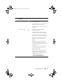
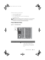
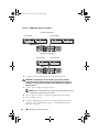
book.book Page 1 Monday, December 7, 2009 4:51 PM
Dell™ PowerVault™
MD1200 and MD1220
Storage Enclosures
Hardware Owner’s
Manual
Regulatory Model: E03J Series and E04J Series
Regulatory Type: E03J001 and E04J001
book.book Page 2 Monday, December 7, 2009 4:51 PM
Notes, Cautions, and Warnings
NOTE: A NOTE indicates important information that helps you make better use of
your computer.
CAUTION: A CAUTION indicates potential damage to hardware or loss of data if
instructions are not followed.
WARNING: A WARNING indicates a potential for property damage, personal
injury, or death.
____________________
Information in this document is subject to change without notice.
© 2009 Dell Inc. All rights reserved.
Reproduction of these materials in any manner whatsoever without the written permission of Dell Inc.
is strictly forbidden.
Trademarks used in this text: Dell, the DELL logo, OpenManage, PowerEdge, and PowerVault are
trademarks of Dell Inc.
Other trademarks and trade names may be used in this document to refer to either the entities claiming
the marks and names or their products. Dell Inc. disclaims any proprietary interest in trademarks and
trade names other than its own.
Regulatory Model: E03J Series and E04J Series
Regulatory Type: E03J001 and E04J001
October 2009
Rev. A00
book.book Page 3 Monday, December 7, 2009 4:51 PM
Contents
1
About Your Enclosure
. . . . . . . . . . . . . . . .
7
Front-Panel Features and Indicators
. . . . . . . . . . .
7
Front-Bezel Features and Indicators
. . . . . . . . . . .
9
Hard-Drive Indicator Patterns .
. . . . . . . . . . . . .
11
. . . . . . . . . .
12
. . . . . . . . . . . .
13
Back-Panel Features and Indicators
Enclosure Management Module
Enclosure Failover When Two EMMs are
Installed . . . . . . . . . . . . . . . . . .
. . . . .
16
. . . . . . . . . . . . .
16
Enclosure Alarms .
. . . . . . . . . . . . . . . . .
16
Power Indicator Codes
. . . . . . . . . . . . . . . . .
17
. . . . . . . . . . . .
18
EMM Thermal Shutdown .
Other Information You May Need
2
Operating Your Storage Enclosure
Before You Begin
. . . . .
19
. . . . . . . . . . . . . . . . . . . .
19
. . . . . . . . . . . . . . . . .
19
Cabling Your Enclosure
Connecting the Enclosure .
. . . . . . . . . . . . . . .
20
. . . . . .
25
. . . . . . . . . . .
26
Changing Your Enclosure’s Operating Mode
Managing Your Storage Enclosure
Contents
3
book.book Page 4 Monday, December 7, 2009 4:51 PM
Downloading Firmware
3
. . . . . . . . . . . . . . . . .
Installing Enclosure Components
. . . . . . . . . . . . . . . . . .
27
Front Bezel (Optional)
. . . . . . . . . . . . . . . . . .
27
. . . . . . . . . . . . .
27
. . . . . . . . . . . . . .
28
. . . . . . . . . . . . . . . . . . . . . . .
29
Installing the Front Bezel
Hard Drives .
Removing a Drive Blank.
. . . . . . . . . . . . . .
29
Installing a Drive Blank .
. . . . . . . . . . . . . .
31
Removing a Hard Drive
. . . . . . . . . . . . . . .
31
Installing a Hard Drive
. . . . . . . . . . . . . . .
32
Removing a Hard Drive From a Hard-Drive
Carrier . . . . . . . . . . . . . . . . . . . .
. . . .
33
Installing a Hard Drive Into a Drive Carrier .
. . . .
35
. . . . . . . . . . . .
35
. . . . . . . . . . . . .
35
Enclosure Management Module.
Removing an EMM Blank .
. . . . . . . . . . . . . .
36
Removing an EMM
. . . . . . . . . . . . . . . . .
37
Installing an EMM.
. . . . . . . . . . . . . . . . .
39
. . . . . . . . . . .
39
Removing a Power Supply/Cooling Fan Module
. .
39
Installing a Power Supply/Cooling Fan Module
. .
41
. . . . . . . . . . . . . . . . . . . . . .
42
Removing the Control Panel
. . . . . . . . . . . .
42
Installing the Control Panel .
. . . . . . . . . . . .
44
. . . . . . . . . . . . . . . . . . . . . . . .
44
Installing an EMM Blank
Power Supply/Cooling Fan Module
Control Panel .
Backplane
Removing the Backplane .
Contents
27
Recommended Tools .
Removing the Front Bezel .
4
. . . . .
26
. . . . . . . . . . . . .
44
book.book Page 5 Monday, December 7, 2009 4:51 PM
Installing the Backplane
4
. . . . . . . . . . . . . .
Troubleshooting Your Enclosure
. . . . . . .
49
Safety First—For You and Your Enclosure
. . . . . . .
49
Troubleshooting Enclosure Startup Failure .
. . . . . .
49
. . . . . . . .
49
. . . . . . . . .
49
Troubleshooting Loss of Communication
Troubleshooting External Connections
Troubleshooting Power Supply/Cooling Fan Module .
Troubleshooting Enclosure Cooling Problems
.
50
. . . . .
51
Troubleshooting Enclosure Management Modules .
Troubleshooting Hard Drives
. .
52
. . . . . . . . . . . . . .
53
. . . . . . . .
54
. . . . . . . . . . .
54
Troubleshooting Enclosure Connections
Troubleshooting a Wet Enclosure .
Troubleshooting a Damaged Enclosure .
5
47
. . . . . . . .
55
. . . . . . . . . . . . . . . . . . . . . .
57
. . . . . . . . . . . . . . . . . . . . .
57
. . . . . . . . . . . . . . . . . . . . . . . . . . . . .
59
. . . . . . . . . . . . . . . . . . . . . . . . . . . . . . .
69
Getting Help .
Contacting Dell
Glossary
Index
Contents
5
book.book Page 6 Monday, December 7, 2009 4:51 PM
6
Contents
book.book Page 7 Monday, December 7, 2009 4:51 PM
About Your Enclosure
Front-Panel Features and Indicators
Figure 1-1.
Front-Panel Features and Indicators—Dell™ PowerVault™ MD1200
1
2
3
4
5
6
Figure 1-2. Front-Panel Features and Indicators—Dell PowerVault MD1220
1
2
3
4
5
6
About Your Enclosure
7
book.book Page 8 Monday, December 7, 2009 4:51 PM
Item
Indicator, Button, or
Connector
1
Enclosure status LED
Icon
Description
The enclosure status LED lights when
the enclosure power is on.
Lights blue during normal operation and
when the host server is identifying
the enclosure.
Blinks blue when a host server is
identifying the enclosure or when the
system identification button is pressed.
Lights amber when the enclosure is
turned on or is reset.
Blinks amber when the enclosure is in
the fault state.
2
Power LED
The power LED lights when at least one
power supply is supplying power to
the enclosure.
3
Split mode LED
The split mode LED lights when
the enclosure is in a split-mode
configuration.
If the LED is not lit, it indicates that
the enclosure is in a unified-mode
configuration.
4
8
System identification
button
About Your Enclosure
The system identification button on the
front control panel can be used to locate
a particular enclosure within a rack.
When the button is pushed, the system
status indicators on the control panel
and the EMM blinks blue until the
button is pushed again.
book.book Page 9 Monday, December 7, 2009 4:51 PM
Item
Indicator, Button, or
Connector
5
Hard drives
Icon
Description
PowerVault MD1200—Up to 12 3.5-inch
SAS hot-swappable hard drives.
PowerVault MD1220—Up to 24 2.5-inch
SAS hot-swappable hard drives.
6
Enclosure mode
switch
When set in the top position, the
enclosure is configured in unified mode.
When set in the bottom position, the
enclosure is configured in split mode.
Front-Bezel Features and Indicators
Figure 1-3. Front-Bezel Features and Indicators
1
2
3
About Your Enclosure
9
book.book Page 10 Monday, December 7, 2009 4:51 PM
Item
Indicator, Button, or
Connector
1
Enclosure status LED
Icon
Description
The enclosure status LED lights when
the enclosure power is on.
Lights blue during normal operation and
when the host server is identifying
the enclosure.
Blinks blue when a host server is
identifying the enclosure or when the
system identification button is pressed.
Lights amber when the enclosure is
turned on or is reset.
Blinks amber when the enclosure is in
the fault state.
2
Power LED
The power LED lights when at least one
power supply is supplying power to
the enclosure.
3
Split mode LED
The split mode LED lights when
the enclosure is in a split-mode
configuration.
If the LED is not lit, it indicates that
the enclosure is in a unified-mode
configuration.
10
About Your Enclosure
book.book Page 11 Monday, December 7, 2009 4:51 PM
Hard-Drive Indicator Patterns
Figure 1-4.
Hard Drive Indicators
1
1
hard-drive activity indicator (green)
2
2
hard-drive status indicator (green
and amber)
Drive-Status Indicator Pattern (RAID Only) Condition
Blinks green two times per second
Identify drive/preparing for removal
Off
Drive ready for insertion or removal
NOTE: The drive status indicator remains
off until all hard drives are initialized after
system power is turned on. Drives are not
ready for insertion or removal during this
time. The Dell PowerEdge™ RAID controller
PERC H800 may take up to a minute to
discover and initialize all the hard drives.
About Your Enclosure
11
book.book Page 12 Monday, December 7, 2009 4:51 PM
Drive-Status Indicator Pattern (RAID Only) Condition
Blinks green, amber, and off
Drive predicted failure
Blinks amber four times per second
Drive failed
Blinks green slowly
Drive rebuilding
Steady green
Drive online
Blinks green three seconds, amber
three seconds, and off six seconds.
Rebuild aborted
Back-Panel Features and Indicators
Figure 1-5. Back-Panel Features and Indicators
1
Item Indicator, Button, or
Connector
1
2
3
12
2
Icon
3
4
5
Description
Power supply/cooling PS 1
fan module
600 W power supply.
Primary enclosure
EMM 0
management module
(EMM)
The EMM provides:
Secondary EMM
• enclosure management functions for your
enclosure.
EMM 1
About Your Enclosure
For more information, see "Power Indicator
Codes" on page 17.
• a data path between the enclosure and the
host server.
book.book Page 13 Monday, December 7, 2009 4:51 PM
Item Indicator, Button, or
Connector
Icon
Description
4
Power switches (2)
The power switch controls the power supply
output to the enclosure.
5
Power supply/cooling PS 2
fan module
600 W power supply.
For more information, see "Power Indicator
Codes" on page 17.
Enclosure Management Module
Each EMM provides the following data path and enclosure management
functions for your enclosure:
•
Monitoring and controlling enclosure environment elements such as
temperature, fan, power supplies, and enclosure LEDs.
•
Controlling access to hard drives.
•
Communicating enclosure attributes and states to the host server.
NOTE: At least one EMM must be installed in the enclosure. If only one EMM is
installed in the enclosure, it must be installed in the primary EMM bay and a blank
must be installed in the secondary EMM bay. See "Installing an EMM Blank" on
page 36.
About Your Enclosure
13
book.book Page 14 Monday, December 7, 2009 4:51 PM
Figure 1-6. Enclosure Management Module
1
2
3
4
Item
Indicator, Button, or
Connector
Icon
1
System status
indicator
Blinks blue when the system
identification button is pushed. You can
identify a particular enclosure in a rack
using the system identification indicator.
2
Debug port
For engineering use only.
3
SAS port (In)
4
In port link status
IN
5
6
7
Description
Provides SAS connections for cabling the
host or an upchain expansion enclosure
(unified mode only).
Lights green when all the links to the
port are connected.
Lights amber when one or more links to
the port are not connected.
The LED remains off if enclosure is not
connected.
5
SAS port (Out)
OUT
Provides SAS connections for cabling to
the next down chain expansion enclosure
in a daisy chain (unified mode only).
NOTE: The SAS port Out is disabled if the
enclosure is running in a split-mode
configuration.
14
About Your Enclosure
book.book Page 15 Monday, December 7, 2009 4:51 PM
Item
Indicator, Button, or
Connector
6
Out port link status
Icon
Description
Lights green when all the links out of the
port are connected.
Lights amber when one or more links out
of the port are not connected.
The LED remains off if enclosure is not
connected.
7
EMM status LED
Lights green when the EMM is
functioning properly.
Lights amber when the enclosure does
not boot or is not properly configured.
Blinks green (On 250 ms* Off 250 ms)
when a firmware download is in progress.
Blinks green (On 1000 ms** Off 1000
ms) when a peer auto-update is in
progress.
Blinks amber (On 250 ms Off 250 ms
[two times]; Off 1000 ms) when the
enclosure is unable to communicate with
enclosure devices.
Blinks amber (On 250 ms *Off 250 ms
[four times]; Off 1000 ms) when a
firmware update fails.
Blinks amber (On 250 ms Off 250 ms
[five times]; Off 1000 ms) when the
firmware versions are different between
two EMMs in an enclosure.
*indicates that the LED blinks fast.
**indicates that the LED blinks slowly.
About Your Enclosure
15
book.book Page 16 Monday, December 7, 2009 4:51 PM
Enclosure Failover When Two EMMs are Installed
If two EMMs are installed, a certain degree of failover is offered. Control and
monitoring of the enclosure elements can be transferred from one EMM to
another in the event of an EMM failure. A failover occurs whenever
communication is lost between an EMM and its peer.
In the event of a peer EMM failure, the surviving EMM activates the amber
status LED of the failed EMM. The surviving EMM then takes over the
responsibility of enclosure management, which includes monitoring and
control of the audible alarm, enclosure LEDs, power supplies, and fans.
Failover does not include providing connectivity to the drives controlled by
the failed EMM. When a failed EMM is replaced, enclosure management
functions do not automatically return to the replaced EMM unless an
additional failure occurs that triggers another failover event. The new EMM
only restores the data path to the hard drives controlled by the failed EMM.
EMM Thermal Shutdown
If critical internal temperatures are reached, the enclosure shuts down
automatically through either a thermal shutdown command issued by the
EMM firmware or through a command from Dell™ OpenManage™ Server
Administrator.
Enclosure Alarms
An audible alarm is activated if any of the fault conditions listed below occur.
The alarm sounds continuously if:
16
•
More than one fan has failed or a power supply/cooling fan module is not
installed.
•
One or more temperature sensors are in critical range.
About Your Enclosure
book.book Page 17 Monday, December 7, 2009 4:51 PM
The alarm sounds every 10 seconds if:
•
One power supply has failed.
•
One cooling fan has failed.
•
One or more temperature sensors are in warning range.
•
One EMM has failed.
NOTE: The alarm is disabled by default. To enable the alarm, you must change the
default setting in Server Administrator. For more information, see the Server
Administrator documentation at support.dell.com/manuals.
Power Indicator Codes
Figure 1-7.
Power Indicator Codes
1
2
3
Item
LED Type
1
DC power
Icon
Description
The LED lights green when the DC
output voltage is within the limit.
If this LED is off, it indicates that the
DC output voltages are not within the
limit.
About Your Enclosure
17
book.book Page 18 Monday, December 7, 2009 4:51 PM
Item
LED Type
2
Power supply/cooling
fan fault
Icon
Description
The LED lights amber when the DC
output voltage is not within the limit or
a fault with the fan is detected.
If this LED is off, it indicates that no
fault condition is present.
3
AC power
The LED lights green when the AC
input voltage is within the limit.
If this LED is off, it indicates either
there is no power or the AC input voltage
is not within the limit.
Other Information You May Need
WARNING: See the safety and regulatory information that shipped with your
system. Warranty information may be included within this document or as a
separate document.
•
The rack documentation included with your rack solution describes how to
install your system into a rack.
•
The Getting Started Guide provides an overview of system features, setting
up your system, and technical specifications.
•
The OpenManage Server Administrator documentation provides
information about managing your storage solution using the storage
management service within the server administrator.
•
The Dell PowerEdge RAID Controller (PERC) H700 and H800 User’s
Guide provides information about configuring RAID.
•
Any media that ships with your system that provides documentation and
tools for configuring and managing your system, including those
pertaining to the operating system, system management software, system
updates, and system components that you purchased with your system.
NOTE: Always check for updates on support.dell.com/manuals and read the
updates first because they often supersede information in other documents.
18
About Your Enclosure
book.book Page 19 Monday, December 7, 2009 4:51 PM
Operating Your Storage Enclosure
Before You Begin
Before connecting your storage enclosure, ensure that the following are
available:
•
Power cables
•
SAS cables
•
Rail kit
•
Dell Systems Management Tools and Documentation media
•
Documentation
–
Getting Started Guide
–
Rack Installation Instructions
–
Safety instructions
Cabling Your Enclosure
You can cable your enclosure in either a unified-mode configuration or in a
split-mode configuration.
•
In a unified-mode configuration your enclosure is connected to one host,
for example, a server with a controller card. Your enclosure can be one of
up to four enclosures daisy-chained to a single port on the controller card
in your host server. The enclosure can also be connected in a redundant
path mode with two connections to single host server. See Figure 2-2 and
Figure 2-3 for cabling diagrams of a unified mode configuration.
•
In a split-mode configuration, your enclosure is connected to two separate
controller cards. The controller cards may reside in the same server or in
two different servers. The enclosure bus is logically split in half where the
first half of the enclosure is managed by one controller and the second half
of the enclosure is managed by the second controller. Table 2-1 lists the
Operating Your Storage Enclosure
19
book.book Page 20 Monday, December 7, 2009 4:51 PM
drives that are controlled by each enclosure management module (EMM)
in a split-mode configuration. See Figure 2-4 for a cabling diagram of a
split-mode configuration.
Table 2-1. Split-Mode Configuration
Enclosure
EMM 0
EMM 1
Dell PowerVault MD1200 Drives 6 to 11
Drives 0 to 5
Dell PowerVault MD1220 Drives 12 to 23
Drives 0 to 11
NOTE: Clustering is not supported on PowerVault MD1200 and
PowerVault M1220 enclosures.
The operating mode is selected using the enclosure mode switch on the front
panel of the enclosure.
NOTE: The enclosure mode switch must be set to either unified mode or split mode
before the enclosure is turned on. Changing the configuration mode after turning on
the enclosure has no effect on the enclosure configuration until the enclosure
is rebooted.
Connecting the Enclosure
1 Ensure that the latest version of Dell OpenManage™ Server Administrator
is installed. For installation instructions and supported operating systems,
see the Server Administrator documentation.
NOTE: The minimum version of Server Administrator supported on your
enclosure is 6.2.
2 Turn off the host system and all attached devices.
3 Connect the SAS cable(s) to the EMM SAS connector on the storage
enclosure and to the RAID controller on the host system. Push the cable
into the connector until it clicks into place. See Figure 2-1.
NOTE: Connectors on both ends of the SAS cable are universally keyed. You
can connect either end of the cable to the EMM or the RAID controller.
NOTE: To remove the SAS cable, you must pull the pull-tab to release the
cable from the connector on the EMM and the host system. See Figure 2-1.
20
Operating Your Storage Enclosure
book.book Page 21 Monday, December 7, 2009 4:51 PM
Figure 2-1. Connecting a SAS Cable
1
1
SAS cable
2
2
pull-tab
NOTE: In a unified-mode configuration, connect the host to the first EMM
module (EMM 0). See Figure 2-2. For unified-mode configurations utilizing
redundant paths, connect the host to the second EMM module (EMM1). See
Figure 2-3.
See your RAID controller documentation to ensure that the controller is
properly installed.
•
If you are configuring your enclosure in a unified-mode configuration,
connect the SAS cable from the host controller to the In port on the
EMM module of the first enclosure in the daisy chain. See Figure 2-2.
Attach subsequent storage enclosures in the daisy chain to the Out
port on the first upchain storage enclosure.
•
If you are configuring your enclosure in a split-mode configuration,
attach the SAS cable from the first host controller to the In port on
the primary EMM module and the SAS cable from the second host
controller port to the In port on the secondary EMM. See Figure 2-4.
NOTE: In a split-mode configuration, you can cable the enclosure to operate
in either a two-host or single-host configuration.
Operating Your Storage Enclosure
21
book.book Page 22 Monday, December 7, 2009 4:51 PM
Figure 2-2. EMM Cabling Diagram in Unified Mode
host controller
22
Operating Your Storage Enclosure
book.book Page 23 Monday, December 7, 2009 4:51 PM
Figure 2-3.
EMM Cabling Diagram in Unified Mode (Redundant Path)
host controller
Operating Your Storage Enclosure
23
book.book Page 24 Monday, December 7, 2009 4:51 PM
Figure 2-4. EMM Cabling Diagram in Split Mode
two-host configuration
host controller
host controller
single-host configuration
host controller
host controller
4 Using the enclosure mode switch, select the operating mode.
CAUTION: To safeguard your storage enclosure against power problems,
connect the AC power cable to a protected power supply, such as a UPS, line
conditioner, or surge protector. If possible, connect the two power supplies to
different circuits.
5 Connect power supplies to the power source.
NOTE: Before connecting the power supplies, ensure that the power switch
on both power supplies is in the OFF position.
6 Turn on the power switches on all power supply/cooling fan modules.
7 Turn on the host system.
8 Check the LED indicators on the front and back panel of the storage
enclosure. If any of the LEDs are amber, see "Troubleshooting Your
Enclosure" on page 49.
24
Operating Your Storage Enclosure
book.book Page 25 Monday, December 7, 2009 4:51 PM
Changing Your Enclosure’s Operating Mode
If you decide to change the operating mode of your enclosure after initial
configuration, you must:
1 Back up all data contained in the enclosure and store the data in a
secure location.
2 When changing the operating mode from:
•
Unified mode to split mode—If existing virtual disks span physical
disks that are split by changing from unified to split mode, remove the
virtual disk configuration.
•
Split mode to unified mode—Some virtual disks may appear as foreign
if the configuration is not deleted before turning the enclosure back on.
These disks must be imported or cleared using either Server
Administrator or the BIOS configuration utility before they can be used.
NOTE: Split-mode configurations do not support daisy-chaining of enclosures
and redundant paths.
3 Turn off the host system.
4 Turn off the enclosure by turning off both power supply/cooling fan modules.
5 Change the position of the enclosure mode switch.
6 Rearrange the disks in the enclosure as necessary.
7 Turn on the enclosure by turning on both power supply/cooling fan modules.
8 Turn on the host system.
9 If required, recreate virtual disks in the enclosure.
Operating Your Storage Enclosure
25
book.book Page 26 Monday, December 7, 2009 4:51 PM
Managing Your Storage Enclosure
Disk storage within the enclosure can be configured using either the BIOS
configuration utility or Server Administrator. For optimal management and
serviceability of your enclosure, it is recommended that you use Server
Administrator.
NOTE: Online configuration, enclosure status, and active event notification is only
supported with Server Administrator version 6.2 or later.
Server Administrator provides a comprehensive server/storage management
solution with an integrated graphical view and command line interface. It
enables online configuration and management for both internal storage and
externally attached storage.
Server Administrator obtains information about physical storage devices, disk
enclosures, virtual disks/RAID arrays, and logical devices and displays the
information in both physical and logical views. Using Server Administrator
you can:
•
create and manage RAID storage configurations
•
display storage information
•
customize event reporting
•
view logged events
For more information, see the Server Administrator documentation at
support.dell.com/manuals.
Downloading Firmware
You can download firmware updates for your storage enclosure using the Dell
Update Package available at support.dell.com.
26
Operating Your Storage Enclosure
book.book Page 27 Monday, December 7, 2009 4:51 PM
Installing Enclosure Components
Recommended Tools
You may need the following items to perform the procedures in this section:
•
Key to the system keylock
•
#2 Phillips screwdriver
•
Wrist grounding strap
Front Bezel (Optional)
Removing the Front Bezel
1 Using the system key, unlock the front bezel (if locked).
2 Lift up the release latch next to the keylock.
3 Rotate the left end of the bezel away from the front panel.
4 Unhook the right end of the bezel and pull the bezel away from
the system.
Installing Enclosure Components
27
book.book Page 28 Monday, December 7, 2009 4:51 PM
Figure 3-1.
Removing and Installing the Front Bezel
1
2
3
4
1
bezel
2
keylock
3
release latch
4
hinge tab
Installing the Front Bezel
1 Hook the right end of the bezel onto the chassis.
2 Fit the free end of the bezel onto the system.
3 Secure the bezel with the keylock. See Figure 3-1.
28
Installing Enclosure Components
book.book Page 29 Monday, December 7, 2009 4:51 PM
Hard Drives
SAFETY: Models AMT, E03J, and E04J
Models AMT, E03J, and E04J are intended for installation only in restricted
access locations as defined in cl 1.2.7.3 of IEC 60950-1:2005.
Depending on your configuration, your enclosure either supports up to 24
2.5-inch SAS hard drives or up to 12 3.5-inch SAS hard drives in internal drive
bays. Hard drives are connected to a backplane through hard-drive carriers
and can be configured as hot-swappable.
CAUTION: Do not turn off or reboot your enclosure while the drive is being
formatted. Doing so can cause a drive to fail.
When you format a hard drive, allow enough time for the formatting to
complete. High-capacity hard drives can take a number of hours to format.
Removing a Drive Blank
CAUTION: To maintain proper system cooling, all empty hard-drive bays must
have drive blanks installed.
1 If installed, remove the front bezel. See "Removing the Front Bezel" on
page 27.
2 Press the release tab and slide the drive blank out until it is free of the
drive bay. See Figure 3-2 for PowerVault MD1200 and Figure 3-3 for
PowerVault MD1220.
Installing Enclosure Components
29
book.book Page 30 Monday, December 7, 2009 4:51 PM
Figure 3-2. Removing and Installing a 3.5-Inch Hard-Drive Blank
1
1
2
drive blank
2
release tab
Figure 3-3. Removing and Installing a 2.5-Inch Hard-Drive Blank
1
1
30
2
drive blank
Installing Enclosure Components
2
release tab
book.book Page 31 Monday, December 7, 2009 4:51 PM
Installing a Drive Blank
1 If installed, remove the front bezel. See "Removing the Front Bezel" on
page 27.
2 Insert the drive blank into the drive bay until the blank is fully seated.
3 Close the handle to lock the blank in place.
4 If applicable, replace the front bezel. See "Installing the Front Bezel" on
page 28.
Removing a Hard Drive
CAUTION: Many repairs may only be done by a certified service technician.
You should only perform troubleshooting and simple repairs as authorized in
your product documentation, or as directed by the online or telephone service
and support team. Damage due to servicing that is not authorized by Dell is not
covered by your warranty. Read and follow the safety instructions that came with
the product.
1 If installed, remove the front bezel. See "Removing the Front Bezel" on
page 27.
2 From the management software, prepare the drive for removal. Wait until
the hard-drive indicators on the drive carrier signal that the drive can be
removed safely. For more information, see your controller documentation
for information about hot-swap drive removal.
If the drive has been online, the green activity/fault indicator flashes as
the drive is powered down. When the drive indicators are off, the drive is
ready for removal.
3 Press the release button to open the drive carrier release handle. See
Figure 3-4.
4 Slide the hard drive out until it is free of the drive bay.
CAUTION: To maintain proper system cooling, all empty hard-drive bays must have
drive blanks installed.
5 Insert a drive blank in the empty drive bay. See "Installing a Drive Blank"
on page 31.
6 If applicable, replace the front bezel. See "Installing the Front Bezel" on
page 28.
Installing Enclosure Components
31
book.book Page 32 Monday, December 7, 2009 4:51 PM
Figure 3-4. Removing and Installing a Hard Drive
1
2
1
release button
2
hard-drive carrier handle
Installing a Hard Drive
CAUTION: Many repairs may only be done by a certified service technician.
You should only perform troubleshooting and simple repairs as authorized in
your product documentation, or as directed by the online or telephone service
and support team. Damage due to servicing that is not authorized by Dell is
not covered by your warranty. Read and follow the safety instructions that came
with the product.
CAUTION: Use only hard drives that have been tested and approved for use with
the SAS backplane.
CAUTION: When installing a hard drive, ensure that the adjacent drives are fully
installed. Inserting a hard-drive carrier and attempting to lock its handle next to a
partially installed carrier can damage the partially installed carrier's shield spring
and make it unusable.
1 If applicable, remove the front bezel. See "Removing the Front Bezel" on
page 27.
2 If applicable, remove the drive blank from the bay. See "Removing a Drive
Blank" on page 29.
3 Press the release button to open the drive carrier release handle.
32
Installing Enclosure Components
book.book Page 33 Monday, December 7, 2009 4:51 PM
4 Insert the hard-drive carrier into the drive bay until the carrier contacts the
backplane.
5 Close the handle to lock the drive in place.
Removing a Hard Drive From a Hard-Drive Carrier
Remove the screws from the slide rails on the hard-drive carrier and separate
the hard drive from the carrier. See Figure 3-5 for PowerVault MD1200 and
Figure 3-6 for PowerVault MD1220.
Figure 3-5. Removing and Installing a Hard Drive Into a 3.5-Inch Drive Carrier
4
1
3
2
Installing Enclosure Components
33
book.book Page 34 Monday, December 7, 2009 4:51 PM
1
screws (4)
2
drive carrier
3
SAS screw hole
4
hard drive
Figure 3-6.
Removing and Installing a Hard Drive Into a 2.5-Inch Drive Carrier
4
1
3
2
34
1
screws (4)
2
drive carrier
3
SAS screw hole
4
hard drive
Installing Enclosure Components
book.book Page 35 Monday, December 7, 2009 4:51 PM
Installing a Hard Drive Into a Drive Carrier
1 Insert the hard drive into the hard-drive carrier with the connector end
of the drive at the back. See Figure 3-5.
2 Align the screw holes on the hard drive with the back set of holes on the
hard-drive carrier.
When aligned correctly, the back of the hard drive is flush with the back of
the hard-drive carrier.
3 Attach the four screws to secure the hard drive to the hard-drive carrier.
Enclosure Management Module
An enclosure with redundant enclosure management contains two enclosure
management modules (EMM) and can be configured in either unified mode
or split mode. An enclosure with non-redundant enclosure management
consists of only one EMM in unified mode. If only one EMM is installed in
your enclosure, it must be installed in EMM 0. You must install the EMM
blank in EMM 1.
CAUTION: EMMs can be removed and installed without turning off the enclosure.
It is recommended that you do not remove the EMM while data is being
transferred. Replacing or installing an EMM that is connected to a host server
causes it to loose communication with the enclosure and requires a reboot of the
host server.
Removing an EMM Blank
CAUTION: To maintain proper system cooling, you must install an EMM blank in
the empty slot.
1 Turn off the enclosure and host server.
2 Disconnect all the power cables connected to the enclosure.
3 Remove EMM 0. See "Removing an EMM" on page 37.
4 To remove the EMM blank, press down on the release latch and pull the
blank away from the enclosure. See Figure 3-7.
5 Install an EMM in EMM 0 and EMM 1. See "Installing an EMM" on
page 39.
Installing Enclosure Components
35
book.book Page 36 Monday, December 7, 2009 4:51 PM
6 Connect all the power cables to the enclosure.
7 Turn on the enclosure and the host server.
Figure 3-7. Removing and Installing an EMM Blank
1
1
release latch
2
2
EMM blank
Installing an EMM Blank
To install an EMM blank, align the blank with the EMM bay and insert the
blank into the chassis until it clicks into place.
36
Installing Enclosure Components
book.book Page 37 Monday, December 7, 2009 4:51 PM
Removing an EMM
CAUTION: Many repairs may only be done by a certified service technician.
You should only perform troubleshooting and simple repairs as authorized in
your product documentation, or as directed by the online or telephone service
and support team. Damage due to servicing that is not authorized by Dell is not
covered by your warranty. Read and follow the safety instructions that came
with the product.
CAUTION: If you remove an EMM from an enclosure operating in split mode
while connected to a host server, you lose connection to the physical disks
attached to the removed EMM.
1 Disconnect the cables connected to the EMM.
2 Push down on the release tab and pull the release lever away from the
chassis. See Figure 3-8.
3 Grasp the release lever and pull the module away from the chassis.
NOTE: To avoid damage to the sensitive EMI contacts on the EMM, do not
stack EMMs.
Installing Enclosure Components
37
book.book Page 38 Monday, December 7, 2009 4:51 PM
Figure 3-8. Removing and Installing an EMM
3
2
1
38
1
EMM
3
release lever
Installing Enclosure Components
2
release tab
book.book Page 39 Monday, December 7, 2009 4:51 PM
Installing an EMM
CAUTION: Many repairs may only be done by a certified service technician. You
should only perform troubleshooting and simple repairs as authorized in your
product documentation, or as directed by the online or telephone service and
support team. Damage due to servicing that is not authorized by Dell is not covered
by your warranty. Read and follow the safety instructions that came with the
product.
1 Insert the EMM into the EMM bay until it seats into place.
2 Push the release lever toward the chassis until it clicks into place.
3 Connect all the cables to the EMM.
4 If applicable, update the firmware for the EMM. For information about
the latest firmware, see the Dell Support website at support.dell.com.
NOTE: If two EMMs are installed in the enclosure, you must ensure that both
the EMMs have the same firmware version installed. You can verify if both the
enclosures use the same firmware version by checking the LEDs on the
enclosure or by using Server Administrator.
For more information about EMM connections and cabling, see "Operating
Your Storage Enclosure" on page 19.
Power Supply/Cooling Fan Module
Your enclosure supports two hot-swappable power supply/cooling fan
modules. While the enclosure can operate temporarily with one module, both
the modules must be present for cooling the enclosure.
CAUTION: A single power supply/cooling fan module can be removed from a
powered-on enclosure for a maximum period of five minutes. Beyond that time, the
enclosure may automatically shut down to prevent damage.
Removing a Power Supply/Cooling Fan Module
NOTE: If you remove a fully functioning power supply/cooling fan module, the fan
speed in the remaining module increases significantly to provide adequate cooling.
The fan speed decreases gradually when a new power supply/cooling fan module
is installed.
1 Turn off the power supply/cooling fan module.
2 Disconnect the power cable from the power source.
Installing Enclosure Components
39
book.book Page 40 Monday, December 7, 2009 4:51 PM
3 Remove the Velcro straps that secure the power cable and then disconnect
the power cable from the power supply/cooling fan module.
WARNING: The power supply/cooling fan modules are heavy. Use both hands
while removing the module.
4 Press the release tab and pull the power supply out of the chassis.
Figure 3-9. Removing and Installing a Power Supply/Cooling Fan Module
OU
T
OU
T
1
2
3
40
1
power supply
3
power supply handle
Installing Enclosure Components
2
release tab
book.book Page 41 Monday, December 7, 2009 4:51 PM
Installing a Power Supply/Cooling Fan Module
1 Slide the power supply/cooling fan module into the chassis until it is fully
seated and the release tab clicks into place. See Figure 3-9.
2 Connect the power cable to the power supply/cooling fan module and plug
the cable into a power outlet.
3 Secure the power cable using the Velcro strap. See Figure 3-10.
Figure 3-10.
Securing the Power Cable
1
1
Velcro strap
CAUTION: When connecting the power cable, secure the cable with the Velcro
strap.
NOTE: If the enclosure is powered on, all the power supply LEDs remain off until
the AC power cable is connected to the power supply/cooling fan module and the
power switch is turned on.
4 Turn on the power supply/cooling fan module.
Installing Enclosure Components
41
book.book Page 42 Monday, December 7, 2009 4:51 PM
Control Panel
Removing the Control Panel
1 Turn off the enclosure and host server.
2 Disconnect all the power cables connected to the enclosure.
3 Remove the hard drives from:
–
slots 0 to 2 in PowerVault MD1200
–
slots 0 to 5 in PowerVault MD1220
See "Removing a Hard Drive" on page 31.
NOTE: Mark each hard drive with it’s slot position as you remove it.
4 Slide the control panel out of the chassis after:
42
–
Pushing the release tab toward the front of the enclosure in
PowerVault MD1200. See Figure 3-11.
–
Pulling the release pin toward the front of the enclosure in PowerVault
MD1220. See Figure 3-12.
Installing Enclosure Components
book.book Page 43 Monday, December 7, 2009 4:51 PM
Figure 3-11.
Removing and Installing the Control Panel—PowerVault MD1200
1
1
2
control panel
Figure 3-12.
2
release tab
Removing and Installing the Control Panel—PowerVault MD1220
2
1
1
control panel
2
release pin
Installing Enclosure Components
43
book.book Page 44 Monday, December 7, 2009 4:51 PM
Installing the Control Panel
1 Align the control panel with the slot on the enclosure.
2 Slide the control panel into the enclosure until:
–
The release tab clicks into place in PowerVault MD1200. See
Figure 3-11.
–
The release pin clicks into place in PowerVault MD1220. See
Figure 3-12.
3 Replace the hard drives in their respective slots. See "Installing a Hard
Drive" on page 32.
4 Connect all the power cables to the enclosure.
5 Turn on the enclosure and the host server.
Backplane
WARNING: Whenever you need to lift the enclosure, get others to assist you. To
avoid injury, do not attempt to lift the enclosure by yourself.
CAUTION: Many repairs may only be done by a certified service technician.
You should only perform troubleshooting and simple repairs as authorized in
your product documentation, or as directed by the online or telephone service
and support team. Damage due to servicing that is not authorized by Dell is not
covered by your warranty. Read and follow the safety instructions that came
with the product.
Removing the Backplane
1 Turn off the enclosure and disconnect it from the electrical outlet.
2 Disconnect all the cables connected to the enclosure.
3 Remove the hard drives. See "Removing a Hard Drive" on page 31.
4 Remove the EMMs. "Removing an EMM" on page 37.
5 Remove the power supply/cooling fan modules. See "Removing a Power
Supply/Cooling Fan Module" on page 39.
6 Remove the control panel. See "Removing the Control Panel" on page 42.
7 Remove the screws that secure the EMM/power supply cage to the chassis.
44
Installing Enclosure Components
book.book Page 45 Monday, December 7, 2009 4:51 PM
8 Grasp the cage removal ring at the bottom center of the enclosure and pull
the EMM/power supply cage toward the back of the chassis. See
Figure 3-13.
9 Lift the EMM/power supply cage away from the chassis. See Figure 3-13.
10 Loosen the captive screw that secures the backplane to the chassis. See
Figure 3-14 for PowerVault MD1200 or Figure 3-15 for PowerVault
MD1220.
11 Remove the screws that secure the backplane and pull the backplane out
of the enclosure. See Figure 3-14 for PowerVault MD1200 or Figure 3-15
for PowerVault MD1220.
Figure 3-13.
Removing and Installing the EMM/Power Supply Cage
2
1
EMM/power supply cage
1
2
screws (6)
Installing Enclosure Components
45
book.book Page 46 Monday, December 7, 2009 4:51 PM
Figure 3-14. Removing and Installing the Backplane—PowerVault MD1200
1
2
3
1
screws (5)
3
captive screw
2
backplane
Figure 3-15. Removing and Installing the Backplane—PowerVault MD1220
1
2
3
46
1
screws (4)
3
captive screw
Installing Enclosure Components
2
backplane
book.book Page 47 Monday, December 7, 2009 4:51 PM
Installing the Backplane
1 Align the holes on the backplane with the holes on the enclosure.
2 Tighten the captive screw to secure the backplane to the chassis.
See Figure 3-14 for PowerVault MD1200 or Figure 3-15 for
PowerVault MD1220.
3 Replace the screws that secure the backplane to the chassis.
See Figure 3-14 for PowerVault MD1200 or Figure 3-15 for
PowerVault MD1220.
4 Align the slots on the EMM/power supply cage with the tabs on the
chassis. See Figure 3-13.
5 Push the EMM/power supply cage toward the front of the enclosure.
6 Replace the screws that secure the EMM/power supply cage to the chassis.
7 Replace the control panel. See "Installing the Control Panel" on page 44.
8 Replace the power supply/cooling fan modules. See "Installing a Power
Supply/Cooling Fan Module" on page 41.
9 Replace the hard drives. See "Installing a Hard Drive" on page 32.
10 Connect all the cables to the enclosure.
11 Turn on the enclosure and the host server.
Installing Enclosure Components
47
book.book Page 48 Monday, December 7, 2009 4:51 PM
48
Installing Enclosure Components
book.book Page 49 Monday, December 7, 2009 4:51 PM
Troubleshooting Your Enclosure
Safety First—For You and Your Enclosure
CAUTION: Many repairs may only be done by a certified service technician.
You should only perform troubleshooting and simple repairs as authorized in
your product documentation, or as directed by the online or telephone service
and support team. Damage due to servicing that is not authorized by Dell is not
covered by your warranty. Read and follow the safety instructions that came
with the product.
Troubleshooting Enclosure Startup Failure
If your system halts during startup, check if:
•
The enclosure emits a series of beeps. See "Enclosure Alarms" on page 16.
•
The enclosure fault LEDs are lit. See "Enclosure Management Module" on
page 13.
•
A message is displayed on the screen. See the Dell™ OpenManage™ Server
Administrator documentation.
•
There is a constant scraping or grinding sound when you access the hard
drive. See "Getting Help" on page 57.
Troubleshooting Loss of Communication
For information about troubleshooting loss of communication, see
"Troubleshooting Enclosure Management Modules" on page 52.
Troubleshooting External Connections
•
Verify that the cables are connected to the correct ports before
troubleshooting any external devices. For the location of the back-panel
connectors on your enclosure, see Figure 1-5.
•
Ensure that all the cables are securely attached to the external connectors
on your enclosure.
Troubleshooting Your Enclosure
49
book.book Page 50 Monday, December 7, 2009 4:51 PM
Troubleshooting Power Supply/Cooling Fan
Module
CAUTION: Many repairs may only be done by a certified service technician.
You should only perform troubleshooting and simple repairs as authorized in
your product documentation, or as directed by the online or telephone service
and support team. Damage due to servicing that is not authorized by Dell is not
covered by your warranty. Read and follow the safety instructions that came
with the product.
CAUTION: It is recommended that you turn off the host server before turning off
the enclosure to prevent loss of data.
1 Locate the faulty power supply and determine the status of the LEDs.
•
If the AC power LED is not lit, check the power cord and power source
into which the power supply is plugged.
•
Connect another device to the power source to verify if it is
working.
•
Connect the cable to a different power source.
•
Replace the power cable.
If the problem is not resolved, see "Getting Help" on page 57.
•
If the DC power LED is not lit, verify that the power switch is turned
on. If the power switch is turned on, see step 2.
•
If the power supply’s fault indicator is lit, see "Getting Help" on
page 57.
CAUTION: Power supply/cooling fan modules are hot-swappable. The enclosure
can operate on a single power supply; however both modules must be installed to
ensure proper cooling. A single power supply/cooling fan module can be removed
from a powered-on enclosure for a maximum period of five minutes. Beyond that
time, the enclosure may automatically shut down to prevent damage.
50
Troubleshooting Your Enclosure
book.book Page 51 Monday, December 7, 2009 4:51 PM
2 Reseat the power supply by removing and reinstalling it. See "Power
Supply/Cooling Fan Module" on page 39.
NOTE: After installing a power supply, allow several seconds for the
enclosure to recognize the power supply and to determine if it is working
properly.
If the problem is not resolved, see "Getting Help" on page 57.
3 If all LEDs on the power supply/cooling fan module are off and if the
enclosure is powered on, you must update the firmware. For information
about updating the firmware, see "Downloading Firmware" on page 26.
Troubleshooting Enclosure Cooling Problems
CAUTION: Many repairs may only be done by a certified service technician.
You should only perform troubleshooting and simple repairs as authorized in
your product documentation, or as directed by the online or telephone service
and support team. Damage due to servicing that is not authorized by Dell is not
covered by your warranty. Read and follow the safety instructions that came
with the product.
Ensure that none of the following conditions exist:
•
Enclosure cover or drive blank is removed.
•
Ambient temperature is too high. See "Technical Specifications" in the
Getting Started Guide.
•
External airflow is obstructed.
•
The power supply/cooling fan module is removed or has failed. See
"Troubleshooting Power Supply/Cooling Fan Module" on page 50.
If the problem is not resolved, see "Getting Help" on page 57.
Troubleshooting Your Enclosure
51
book.book Page 52 Monday, December 7, 2009 4:51 PM
Troubleshooting Enclosure Management
Modules
CAUTION: Many repairs may only be done by a certified service technician.
You should only perform troubleshooting and simple repairs as authorized in
your product documentation, or as directed by the online or telephone service
and support team. Damage due to servicing that is not authorized by Dell is not covered
by your warranty. Read and follow the safety instructions that came with the product.
CAUTION: It is recommended that you turn off the host server before turning off the
enclosure to prevent loss of data.
•
If the EMM status LED is solid or blinking amber (2 or 4 times per sequence):
a
Turn off the server.
b
Remove the EMM and verify that the pins on backplane and EMM are
not bent. See "Removing an EMM" on page 37.
c
Reinstall the EMM and wait for 30 seconds. See "Installing an EMM" on
page 39.
d
Turn on the server.
e
Check the EMM status LED.
If the problem is not resolved, see "Getting Help" on page 57.
•
If EMM status LED is blinking amber (5 times per sequence), update the
firmware to the latest supported firmware on both the EMMs. For more
information about downloading the latest firmware, see "Downloading
Firmware" on page 26.
•
If the link status LEDs are not green:
a
Turn off the server.
b
Reseat the cables on the storage enclosure and the server.
c
Restart the storage enclosure and wait until enclosure is fully booted.
d
Turn on the server.
e
Check the link status LED. If the link status LED is not green, proceed to
the next step.
f
Replace the cables.
If the problem is not resolved, see "Getting Help" on page 57.
52
Troubleshooting Your Enclosure
book.book Page 53 Monday, December 7, 2009 4:51 PM
Troubleshooting Hard Drives
CAUTION: Many repairs may only be done by a certified service technician.
You should only perform troubleshooting and simple repairs as authorized in
your product documentation, or as directed by the online or telephone service
and support team. Damage due to servicing that is not authorized by Dell is not
covered by your warranty. Read and follow the safety instructions that came
with the product.
1 Remove the hard drive from the enclosure. See "Removing a Hard Drive"
on page 31.
NOTE: You must ensure that you check the hard drive indicators before
removing the faulty hard drive from the enclosure.
2 Check the hard drives and the backplane to ensure that the connectors are
not damaged.
3 Reinstall the hard drive.
4 Reboot the host server.
If the problem is not resolved, proceed to step 5.
5 Verify that the EMM port link status LED and the EMM status LED are
solid green for each port that is connected to a cable. If the LEDs are not
solid green, see "Enclosure Management Module" on page 13.
6 Ensure that all the cables are attached correctly according to the enclosure
mode you selected. For more information on enclosure modes, see
"Operating Your Storage Enclosure" on page 19.
7 If you reseated the cables, reboot the host server.
If the problem persists, see "Troubleshooting Loss of Communication" on
page 49 or see "Getting Help" on page 57.
Troubleshooting Your Enclosure
53
book.book Page 54 Monday, December 7, 2009 4:51 PM
Troubleshooting Enclosure Connections
1 Verify that the EMM port link status LED and the EMM status LED are
solid green for each port that is connected to a cable. If the LEDs are not
solid green, see "Enclosure Management Module" on page 13.
2 Ensure that all the cables are attached correctly according to enclosure
mode you selected. For more information about enclosure modes, see
"Operating Your Storage Enclosure" on page 19.
3 If you reseated cables, reboot the host server.
NOTE: You must turn off the host server before reseating the cables on
the enclosure.
If the problem is not resolved, see "Getting Help" on page 57.
Troubleshooting a Wet Enclosure
CAUTION: Many repairs may only be done by a certified service technician.
You should only perform troubleshooting and simple repairs as authorized in
your product documentation, or as directed by the online or telephone service
and support team. Damage due to servicing that is not authorized by Dell is not
covered by your warranty. Read and follow the safety instructions that came
with the product.
1 Turn off the enclosure and disconnect all the cables.
2 Remove the following components from the enclosure. See "Installing
Enclosure Components" on page 27.
•
Hard drives
•
Enclosure Management Modules (EMMs)
•
Power supply/cooling fan modules
•
Control panel
•
Backplane
3 Let the system dry thoroughly for at least 24 hours.
4 Reinstall the components you removed in step 2.
5 Connect all the cables and turn on the enclosure.
If the enclosure does not start properly, see "Getting Help" on page 57.
54
Troubleshooting Your Enclosure
book.book Page 55 Monday, December 7, 2009 4:51 PM
Troubleshooting a Damaged Enclosure
CAUTION: Many repairs may only be done by a certified service technician.
You should only perform troubleshooting and simple repairs as authorized in
your product documentation, or as directed by the online or telephone service
and support team. Damage due to servicing that is not authorized by Dell is not
covered by your warranty. Read and follow the safety instructions that came
with the product.
1 Ensure that the following components are properly installed:
•
Hard drives
•
EMMs
•
Power supply/cooling fan modules
•
Control panel
•
Backplane
2 Ensure that all the cables are properly connected and that there are no
damaged pins in the connectors.
3 Run diagnostics available in Server Administrator.
If the test fails, see "Getting Help" on page 57.
Troubleshooting Your Enclosure
55
book.book Page 56 Monday, December 7, 2009 4:51 PM
56
Troubleshooting Your Enclosure
book.book Page 57 Monday, December 7, 2009 4:51 PM
Getting Help
Contacting Dell
For customers in the United States, call 800-WWW-DELL (800-999-3355).
NOTE: If you do not have an active Internet connection, you can find contact
information on your purchase invoice, packing slip, bill, or Dell product catalog.
Dell provides several online and telephone-based support and service options.
Availability varies by country and product, and some services may not be
available in your area. To contact Dell for sales, technical support, or
customer service issues:
1 Visit support.dell.com.
2 Verify your country or region in the Choose A Country/Region drop-down
menu at the bottom of the page.
3 Click Contact Us on the left side of the page.
4 Select the appropriate service or support link based on your need.
5 Choose the method of contacting Dell that is convenient for you.
Getting Help
57
book.book Page 58 Monday, December 7, 2009 4:51 PM
58
Getting Help
book.book Page 59 Monday, December 7, 2009 4:51 PM
Glossary
A — Ampere(s).
AC — Alternating current.
ACPI — Advanced Configuration and Power Interface. A standard interface for
enabling the operating system to direct configuration and power management.
ambient temperature — The temperature of the area or room where the system is
located.
ANSI — American National Standards Institute. The primary organization for
developing technology standards in the U.S.
asset tag — An individual code assigned to a system, usually by an administrator, for
security or tracking purposes.
backup — A copy of a program or data file. As a precaution, back up your system’s
hard drive(s) on a regular basis.
blade — A module that contains a processor, memory, and a hard drive. The modules
are mounted into a chassis that includes power supplies and fans.
BMC — Baseboard management controller.
bootable media — A CD, diskette, or USB memory key that is used to start your
system if the system does not boot from the hard drive.
BTU — British thermal unit.
bus — An information pathway between the components of a system. Your system
contains an expansion bus that allows the processor to communicate with controllers
for the peripheral devices connected to the system. Your system also contains an
address bus and a data bus for communications between the processor and RAM.
C — Celsius.
cache — A fast storage area that keeps a copy of data or instructions for quick data
retrieval.
cm — Centimeter(s).
COMn — The device names for the serial ports on your system.
control panel — The part of the system that contains indicators and controls, such as
the power button and power indicator.
controller — A chip or expansion card that controls the transfer of data between the
processor and memory or between the processor and a peripheral device.
coprocessor — A chip that relieves the system’s processor of specific processing tasks.
A math coprocessor, for example, handles numeric processing.
Glossary
59
book.book Page 60 Monday, December 7, 2009 4:51 PM
CPU — Central processing unit. See processor.
DC — Direct current.
DDR — Double-data rate. A technology in memory modules that potentially doubles
the data rate by transferring data on both the rising and falling pulses of a clock cycle.
device driver — A program that allows the operating system or some other program to
interface correctly with a peripheral.
DHCP — Dynamic Host Configuration Protocol. A method of automatically
assigning an IP address to a client system.
diagnostics — A comprehensive set of tests for your system.
DIMM — Dual in-line memory module. See also memory module.
DNS — Domain Name System. A method of translating Internet domain names, such
as www.example.com, into IP addresses, such as 208.77.188.166.
DRAM — Dynamic random-access memory. A system’s RAM is usually made up
entirely of DRAM chips.
driver — See device driver.
DVD — Digital versatile disc or digital video disc.
ECC — Error checking and correction.
EMI — Electromagnetic interference.
ERA — Embedded remote access. ERA allows you to perform remote, or "out-ofband," server management on your network server using a remote access controller.
ESD — Electrostatic discharge.
ESM — Embedded server management.
expansion bus — Your system contains an expansion bus that allows the processor to
communicate with controllers for peripherals, such as NICs.
expansion card — An add-in card, such as a NIC or SCSI adapter, that plugs into an
expansion-card connector on the system board. An expansion card adds some
specialized function to the system by providing an interface between the expansion
bus and a peripheral.
expansion-card connector — A connector on the system board or riser board for
plugging in an expansion card.
F — Fahrenheit.
FAT — File allocation table. The file system structure used by MS-DOS to organize
and keep track of file storage. The Microsoft® Windows® operating systems can
optionally use a FAT file system structure.
Fibre Channel — A high-speed network interface used primarily with networked
60
Glossary
book.book Page 61 Monday, December 7, 2009 4:51 PM
storage devices.
flash memory — A type of electronic chip that can be programmed and
reprogrammed using a software utility.
FSB — Front-side bus. The FSB is the data path and physical interface between the
processor and the main memory (RAM).
FTP — File transfer protocol.
g — Gram(s).
G — Gravities.
Gb — Gigabit(s); 1024 megabits or 1,073,741,824 bits.
GB — Gigabyte(s); 1024 megabytes or 1,073,741,824 bytes. However, when referring
to hard-drive capacity, the term is usually rounded to 1,000,000,000 bytes.
graphics mode — A video mode that can be defined as x horizontal by y vertical pixels
by z colors.
host adapter — A controller that implements communication between the system’s
bus and the peripheral device, typically a storage device.
hot-plug — The ability to insert or install a device, typically a hard drive or an internal
cooling fan, into the host system while the system is powered on and running.
Hz — Hertz.
I/O — Input/output. A keyboard is an input device, and a monitor is an output device.
In general, I/O activity can be differentiated from computational activity.
IDE — Integrated drive electronics. A standard interface between the system board
and storage devices.
iDRAC — Internet Dell Remote Access Controller. A remote access controller that
uses the Internet SCSI protocol.
InfiniBand —
IP — Internet Protocol.
IPv6 — Internet Protocol version 6.
IPX — Internet package exchange.
IRQ — Interrupt request. A signal that data is about to be sent to or received by a
peripheral device travels by an IRQ line to the processor. Each peripheral connection
must be assigned an IRQ number. Two devices can share the same IRQ assignment,
but you cannot operate both devices simultaneously.
iSCSI — Internet SCSI (see SCSI). A protocol that enables SCSI device
communication across a network or the Internet.
jumper — Small blocks on a circuit board with two or more pins emerging from them.
Glossary
61
book.book Page 62 Monday, December 7, 2009 4:51 PM
Plastic plugs containing a wire fit down over the pins. The wire connects the pins and
creates a circuit, providing a simple and reversible method of changing the circuitry in
a board.
K — Kilo-; 1000.
Kb — Kilobit(s); 1024 bits.
KB — Kilobyte(s); 1024 bytes.
Kbps — Kilobit(s) per second.
KBps — Kilobyte(s) per second.
kg — Kilogram(s); 1000 grams.
kHz — Kilohertz.
KVM — Keyboard/video/mouse. KVM refers to a switch that allows selection of the
system from which the video is displayed and for which the keyboard and mouse are
used.
LAN — Local area network. A LAN is usually confined to the same building or a few
nearby buildings, with all equipment linked by wiring dedicated specifically to the
LAN.
LCD — Liquid crystal display.
LED — Light-emitting diode. An electronic device that lights up when a current is
passed through it.
LGA — Land grid array.
local bus — On a system with local-bus expansion capability, certain peripheral
devices (such as the video adapter circuitry) can be designed to run much faster than
they would with a traditional expansion bus. See also bus.
LOM — LAN on motherboard.
LVD — Low voltage differential.
m — Meter(s).
mA — Milliampere(s).
MAC address — Media Access Control address. Your system’s unique hardware
number on a network.
mAh — Milliampere-hour(s).
Mb — Megabit(s); 1,048,576 bits.
MB — Megabyte(s); 1,048,576 bytes. However, when referring to hard-drive capacity,
the term is often rounded to mean 1,000,000 bytes.
Mbps — Megabits per second.
62
Glossary
book.book Page 63 Monday, December 7, 2009 4:51 PM
MBps — Megabytes per second.
MBR — Master boot record.
memory address — A specific location, usually expressed as a hexadecimal number, in
the system’s RAM.
memory module — A small circuit board containing DRAM chips that connects to the
system board.
memory — An area in your system that stores basic system data. A system can contain
several different forms of memory, such as integrated memory (ROM and RAM) and
add-in memory modules (DIMMs).
memory key — A portable flash memory storage device integrated with a USB
connector.
MHz — Megahertz.
mirroring — A type of data redundancy in which a set of physical drives stores data
and one or more sets of additional drives stores duplicate copies of the data. Mirroring
functionality is provided by software. See also striping and RAID.
mm — Millimeter(s).
ms — Millisecond(s).
NAS — Network Attached Storage. NAS is one of the concepts used for implementing
shared storage on a network. NAS systems have their own operating systems,
integrated hardware, and software that are optimized to serve specific storage needs.
NIC — Network interface controller. A device that is installed or integrated in a
system to allow connection to a network.
NMI — Nonmaskable interrupt. A device sends an NMI to signal the processor about
hardware errors.
ns — Nanosecond(s).
NVRAM — Nonvolatile random-access memory. Memory that does not lose its
contents when you turn off your system. NVRAM is used for maintaining the date,
time, and system configuration information.
parity — Redundant information that is associated with a block of data.
parity stripe — In RAID arrays, a striped hard drive containing parity data.
partition — You can divide a hard drive into multiple physical sections called
partitions with the fdisk command. Each partition can contain multiple logical drives.
You must format each logical drive with the format command.
PCI — Peripheral Component Interconnect. A standard for local-bus
implementation.
Glossary
63
book.book Page 64 Monday, December 7, 2009 4:51 PM
PDU — Power distribution unit. A power source with multiple power outlets that
provides electrical power to servers and storage systems in a rack.
peripheral — An internal or external device, such as a diskette drive or keyboard,
connected to a system.
pixel — A single point on a video display. Pixels are arranged in rows and columns to
create an image. A video resolution, such as 640 x 480, is expressed as the number of
pixels across by the number of pixels up and down.
POST — Power-on self-test. Before the operating system loads when you turn on your
system, the POST tests various system components such as RAM and hard drives.
processor — The primary computational chip inside the system that controls the
interpretation and execution of arithmetic and logic functions. Software written for
one processor must usually be revised to run on another processor. CPU is a synonym
for processor.
PXE — Preboot eXecution Environment. A way of booting a system via a LAN
(without a hard drive or bootable diskette).
RAC — Remote access controller.
RAID — Redundant array of independent disks. A method of providing data
redundancy. Some common implementations of RAID include RAID 0, RAID 1, RAID
5, RAID 10, and RAID 50. See also mirroring and striping.
RAM — Random-access memory. The system’s primary temporary storage area for
program instructions and data. Any information stored in RAM is lost when you turn
off your system.
R-DIMM — A registered DDR3 memory module.
readme file — A text file, usually shipped with software or hardware, that contains
information supplementing or updating the product’s documentation.
read-only file — A read-only file is one that you are prohibited from editing or
deleting.
ROM — Read-only memory. Your system contains some programs essential to its
operation in ROM code. A ROM chip retains its contents even after you turn off your
system. Examples of code in ROM include the program that initiates your system’s
boot routine and the POST.
ROMB — RAID on motherboard.
SAN — Storage Area Network. A network architecture that enables remote networkattached storage devices to appear to a server to be locally attached.
SAS — Serial-attached SCSI.
SATA — Serial Advanced Technology Attachment. A standard interface between the
64
Glossary
book.book Page 65 Monday, December 7, 2009 4:51 PM
system board and storage devices.
SCSI — Small computer system interface. An I/O bus interface with faster data
transmission rates than standard ports.
SD card — Secure digital flash memory card.
SDRAM — Synchronous dynamic random-access memory.
sec — Second(s).
serial port — A legacy I/O port with a 9-pin connector that transfers data one bit at a
time and is most often used to connect a modem to the system.
service tag — A bar code label on the system used to identify it when you call Dell for
technical support.
SMART — Self-Monitoring Analysis and Reporting Technology. Allows hard drives to
report errors and failures to the system BIOS and then display an error message on the
screen.
SMP — Symmetric multiprocessing. Used to describe a system that has two or more
processors connected via a high-bandwidth link and managed by an operating system,
where each processor has equal access to I/O devices.
SNMP — Simple Network Management Protocol. A standard interface that allows a
network manager to remotely monitor and manage workstations.
striping — Disk striping writes data across three or more disks in an array, but only
uses a portion of the space on each disk. The amount of space used by a "stripe" is the
same on each disk used. A virtual disk may use several stripes on the same set of disks
in an array. See also guarding, mirroring, and RAID.
SVGA — Super video graphics array. VGA and SVGA are video standards for video
adapters with greater resolution and color display capabilities than previous standards.
system board — As the main circuit board, the system board usually contains most of
your system’s integral components, such as the processor(s), RAM, controllers for
peripherals, and various ROM chips.
system configuration information — Data stored in memory that tells a system what
hardware is installed and how the system should be configured for operation.
system memory — See RAM.
System Setup program — A BIOS-based program that allows you to configure your
system’s hardware and customize the system’s operation by setting features such as
password protection. Because the System Setup program is stored in NVRAM, any
settings remain in effect until you change them again.
TCP/IP — Transmission Control Protocol/Internet Protocol.
termination — Some devices (such as the last device at each end of a SCSI cable)
Glossary
65
book.book Page 66 Monday, December 7, 2009 4:51 PM
must be terminated to prevent reflections and spurious signals in the cable. When
such devices are connected in a series, you may need to enable or disable the
termination on these devices by changing jumper or switch settings on the devices or
by changing settings in the configuration software for the devices.
TOE — TCP/IP offload engine.
U-DIMM — An unregistered (unbuffered) DDR3 memory module.
uplink port — A port on a network hub or switch used to connect to other hubs or
switches without requiring a crossover cable.
UPS — Uninterruptible power supply. A battery-powered unit that automatically
supplies power to your system in the event of an electrical failure.
USB — Universal Serial Bus. A USB connector provides a single connection point for
multiple USB-compliant devices, such as mice and keyboards. USB devices can be
connected and disconnected while the system is running.
USB memory key — See memory key.
utility — A program used to manage system resources—memory, disk drives, or
printers, for example.
V — Volt(s).
VAC — Volt(s) alternating current.
VDC — Volt(s) direct current.
VGA — Video graphics array. VGA and SVGA are video standards for video adapters
with greater resolution and color display capabilities than previous standards.
video adapter — The logical circuitry that provides (in combination with the monitor)
your system’s video capabilities. A video adapter may be integrated into the system
board or may be an expansion card that plugs into an expansion slot.
video memory — Most VGA and SVGA video adapters include memory chips in
addition to your system’s RAM. The amount of video memory installed primarily
influences the number of colors that a program can display (with the appropriate video
drivers and monitor capabilities).
video resolution — Video resolution (800 x 600, for example) is expressed as the
number of pixels across by the number of pixels up and down. To display a program at
a specific graphics resolution, you must install the appropriate video drivers and your
monitor must support the resolution.
virtualization — The ability via software to share the resources of a single computer
across multiple environments. A single physical system may appear to the user as
multiple virtual systems able to host multiple operating systems.
W — Watt(s).
66
Glossary
book.book Page 67 Monday, December 7, 2009 4:51 PM
WH — Watt-hour(s).
XML — Extensible Markup Language. XML is a way to create common information
formats and to share both the format and the data on the World Wide Web, intranets,
and elsewhere.
ZIF — Zero insertion force.
Glossary
67
book.book Page 68 Monday, December 7, 2009 4:51 PM
68
Glossary
book.book Page 69 Monday, December 7, 2009 4:51 PM
Index
A
E
alarms, 16
enclosure
managing, 26
backplane
installing, 47
removing, 44
enclosure mode
cabling, 19
changing, 25
split, 19
unified, 19
C
F
cabling
split mode, 20
unified mode, 20
firmware
downloading, 26
B
contacting Dell, 57
control panel
installing, 44
removing, 42
front bezel
installing, 28
removing, 27
front panel
features, 7
D
H
Dell
contacting, 57
hard drive
drive carrier, 33
installing, 32
removing, 31
drive carrier
hard drive, 33
I
indicators
Index
69
book.book Page 70 Monday, December 7, 2009 4:51 PM
hard drive, 31
hard drive from a drive carrier, 33
power supply/cooling fan
module, 39
power, 7
installing
backplane, 47
control panel MD1200, 44
drive blank, 31
EMM, 39
EMM blank, 36
front bezel, 28
hard drive, 32
hard drives, 32
power supply/cooling fan
module, 41
S
safety, 49
support
contacting Dell, 57
T
M
telephone numbers, 57
managing
storage enclosure, 26
thermal shutdown, 16
P
phone numbers, 57
power indicators, 7
R
recommended tools, 27
removing
backplane, 44
control panel MD1200, 42
drive blank, 29
EMM, 37
EMM blank, 35
front bezel, 27
troubleshooting, 49
connections, 54
cooling problems, 51
damaged enclosure, 55
external connections, 49
hard drives, 53
loss of communication, 49
power supply/cooling fan
module, 50
startup failure, 49
wet enclosure, 54
W
warranty, 18
Index
70