1
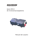
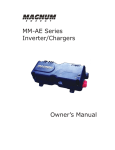
M a in t e n a n ce a n d Tr ou ble sh oot in g
4 .0 M a in t e n a n ce a n d Tr ou ble sh oot in g
The following information is provided to help you keep your ME Series inverter/charger in optimum
operational condition.
4 .1
Re com m e n de d I n ve r t e r a n d Ba t t e r y Ca r e
The ME Series inverter/charger is designed to provide you with years of trouble-free service. Even
though there are no user-serviceable parts, it is recommended that every 6 months you perform the
following maintenance steps to ensure optimum performance and extend the life of your batteries.
W ARN I N G: Prior to performing the following checks, switch OFF both the AC and
DC circuits.
•
Visually inspect the batteries for cracks, leaks, or swelling—replace if necessary.
•
Use baking soda to clean and remove any electrolyte spills or buildups.
•
Check and tighten all battery hold down clamps (if applicable).
•
Clean and tighten all battery terminals and connecting cables [10 to 12 ft lbf
(13.6 to 16.3 N-m)].
•
Check and fill battery water levels (Liquid Lead Acid batteries only).
•
Check individual battery voltages (load test those that have a voltage difference of more
than 0.3 VDC from each other)—replace if necessary.
•
Check all cable runs for signs of chafing—replace if necessary.
•
Check the inverter’s cooling vents—clean as necessary.
•
Check and tighten the inverter’s internal AC terminal block connections
[16 in lbf (1.8 N-m)].
4 .2
St or a ge for M obile I n st a lla t ion s
When placing the RV, boat, or truck into storage, it is recommended that you perform the following
to ensure the system is properly shut down (or properly configured for storage). This is especially
important for maintaining the batteries.
•
Perform the recommended maintenance steps listed in Section 4.1.
•
Fully charge the batteries.
•
Connect AC power (if available) and verify the breaker to the inverter’s input is switched
ON (to allow battery charging).
•
Verify the inverter is switched OFF.
•
Switch OFF all unnecessary AC and DC loads.
•
Disable the AGS (if installed) when the RV, boat, or truck is in a confined storage area.
W ARN I N G: If an AGS were to start and run the generator for an extended period
of time in a confined area, a potentially fatal level of carbon monoxide (CO) could
accumulate.
Page 48
© 2012 Magnum Energy, Inc
M a in t e n a n ce a n d Tr ou ble sh oot in g
4 .3
Tr ou ble sh oot in g
The ME Series inverter/charger is a fairly simple device to troubleshoot. The following chart is
designed to help you quickly pinpoint the most common inverter failures.
Ta ble 4 - 1 , Ba sic Tr ou ble sh oot in g
Sym pt om
Possible Ca u se
N o o u t p u t p o w e r. Inverter is switched OFF
Inverter LED is OFF
Battery voltage is too low. The battery
voltage level has dropped below the
Low Battery Cutout (LBCO) set-point
for more than one minute.
Re com m e n de d Solu t ion
Switch the inverter ON.
Check fuses/circuit-breakers and cable connections.
Check battery voltage at the inverter’s terminals. Your
batteries may need to be charged, this fault condition
will automatically clear when the battery voltage exceeds
the LBCI voltage.
The battery voltage is too high. The
inverter automatically resets and
resumes operation when the battery
voltage drops to the HBCI voltage or
lower.
This condition usually only occurs when an additional
charging source (alternator, solar panels, or other
external charging sources) is used to charge the battery
bank. Reduce or turn off any other charger to the inverter
batteries to allow the voltage level to drop.
Over-temperature condition: The
internal temperature of the inverter has
risen above acceptable limits; caused
by loads too great for the inverter to
operate continuously, or by lack of
ventilation to the inverter. When the
unit has cooled, it will automatically
reset and resume operation.
Reduce the number of electrical loads that you are
operating, this will avoid a repeat over-temp shutdown if
the cause was too many loads for the ambient conditions.
Check ventilation around the inverter, ensure cool air is
available to pass-thru the inverter (refer to the ventilation
requirements in Section 2.1.3).
AC overload condition: The inverter Reduce the AC loads connected to the inverter, or remove
has turned off because the connected all AC output wiring and restart the inverter.
loads are larger than the inverter’s
output capacity, or the output wires
are shorted.
Internal fault: This fault occurs when To clear this fault, an inverter reset is required. Remove
an internal fault is detected.
DC power to the inverter, or press and hold down the
power switch on the inverter for 15 seconds (until the
green Status LED comes on). If this fault does not clear,
the unit will need to be serviced.
N o o u t p u t p o w e r. Unit is in Search mode, which means Turn on a load greater than 5 watts to bring inverter to
Green LED is flashing. load is too small for Search mode full output power, or turn off search with remote.
circuit detection.
Low output or surge Loose or corroded battery cables.
power. Green LED is
Low batteries.
flashing.
Loose AC output connections.
Clean and tighten all cables.
Recharge or replace batteries.
Tighten AC output connections.
Battery cables are the wrong length Verify recommended cable lengths and gauges from the
or gauge.
manual. Replace cables as necessary.
L o w c h a r g i n g ra t e Charge rate set too low.
when connected to AC
Low AC voltage (< 90 VAC).
power.
Adjust charge rate or SHORE settings on remote.
Check AC input wiring.
Low charging rate when Generator output is too low to power Reduce the load, increase the generator’s RPMs.
using a generator.
both load and charger.
Check the SHORE settings (if remote connected).
C h a r g e r d o e s n o t Loose or corroded battery cables.
charge.
Defective batteries.
While charging, the
DC charge voltage is
higher or lower than
expected.
Clean and tighten battery cables.
Replace batteries.
Wrong charger settings.
Adjust the charger settings, ensure the unit is not in
charger standby.
Wrong AC input voltage.
Verify proper AC input voltage and frequency.
If the Battery Temperature Sensor This is normal; see Section 3.5 (Battery Temperature
(BTS) is installed, the DC voltage will Sensor Operation) for more information.
increase or decrease depending on the
temperature around the BTS.
© 2012 Magnum Energy, Inc.
Page 49
M a in t e n a n ce a n d Tr ou ble sh oot in g
4 .4
Pe r for m in g a n I n ve r t e r Re se t
Certain faults require the inverter to be reset. To perform an inverter reset (also known as a soft
reset), press and hold the Power ON/OFF button (see Figure 4-1) for approximately fifteen (15)
seconds until the Charging/Inverting Status LED comes on and flashes rapidly. Once the rapid
flashing has begun, release the Power ON/OFF button. The Status LED will go off after the button
is released.
After the inverter reset is completed, press the Power ON/OFF button to turn the inverter ON.
Some older inverter models do not allow an inverter reset. If the inverter reset fails, you will need
to perform a power reset using the procedure below. In either case, if an internal fault does not
clear, the inverter will require repair at a Magnum Authorized Service Center (ASC).
I n fo: The Power ON/OFF pushbutton is a small momentary type switch which operates
by lightly pressing and releasing. Be careful not to apply too much force when pushing
or the switch might break.
1. Press and hold the Power
ON/OFF pushbutton.
2. Watch the Charging/Inverting
Status LED, after approximately
15 seconds it should come on
and flash rapidly to indicate the
inverter has reset. The Status LED
will go off after the pushbutton is
released.
Figu r e 4 - 1 , Pe r for m in g a n I n ve r t e r Re se t
4 .5
Pe r for m in g a Pow e r Re se t
To
1.
2.
3.
perform a power reset (also known as a hard reset):
Remove all AC power (utility or generator power) to the inverter.
Open all the inverter DC disconnects (or disconnect the positive battery cable to the inverter).
Ensure the inverter(s) and the remote are disconnected from all AC and DC power (the
remote display will be blank).
4. After the inverter(s) has been disconnected from all power for 30 seconds, reconnect the
inverter DC disconnects (or reconnect the positive battery cable) and resume operation.
I n fo: If DC disconnects are not used, there may be a momentary spark when the
positive battery cable is connected to the inverter’s terminal. This is normal and
indicates that the inverter’s internal capacitors are being charged.
Page 50
© 2012 Magnum Energy, Inc