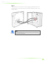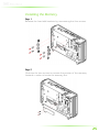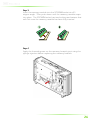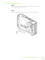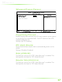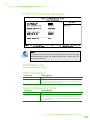
1
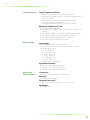
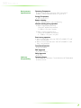
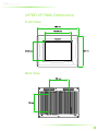
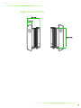
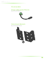
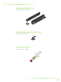
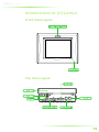
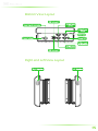
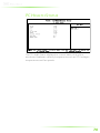
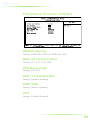
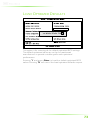
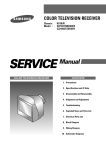
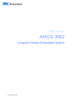
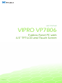
user manual
VIPRO VP7806
Fanless Panel PC with
6.5” TFT LCD and Touch Screen
Revision 1.0
100-04122010-1958
Copyright and Trademarks
Copyright © 2010 VIA Technologies Incorporated. All rights reserved.
No part of this document may be reproduced, transmitted, transcribed, stored in a
retrieval system, or translated into any language, in any form or by any means, electronic,
mechanical, magnetic, optical, chemical, manual or otherwise without the prior written
permission of VIA Technologies, Incorporated.
All trademarks are the property of their respective holders.
PS/2 is a registered trademark of IBM Corporation.
Disclaimer
No license is granted, implied or otherwise, under any patent or patent rights of VIA
Technologies. VIA Technologies makes no warranties, implied or otherwise, in regard to
this document and to the products described in this document. The information provided
in this document is believed to be accurate and reliable as of the publication date of this
document. However, VIA Technologies assumes no responsibility for the use or misuse of
the information in this document and for any patent infringements that may arise from the
use of this document. The information and product specifications within this document are
subject to change at any time, without notice and without obligation to notify any person
of such change.
Regulatory Compliance
FCC-A Radio Frequency Interference Statement
This equipment has been tested and found to comply with the limits for a class A digital
device, pursuant to part 15 of the FCC rules. These limits are designed to provide
reasonable protection against harmful interference when the equipment is operated in a
commercial environment. This equipment generates, uses, and can radiate radio
frequency energy and, if not installed and used in accordance with the instruction manual,
may cause harmful interference to radio communications. Operation of this equipment in a
residential area is likely to cause harmful interference, in which case the user will be
required to correct the interference at his personal expense.
Notice 1
The changes or modifications not expressly approved by the party responsible for
compliance could void the user's authority to operate the equipment.
Notice 2
Shielded interface cables and A.C. power cord, if any, must be used in order to comply
with the emission limits.
Tested To Comply
With FCC Standards
FOR HOME OR OFFICE USE
Battery Recycling and Disposal
Only use the appropriate battery specified for this product.
Do not re-use, recharge, or reheat an old battery.
Do not attempt to force open the battery.
Do not discard used batteries with regular trash.
Discard used batteries according to local regulations.
II
Safety Precautions
Do’s
o
Always read the safety instructions carefully.
o
Keep this User's Manual for future reference.
o
All cautions and warnings on the equipment should be
noted.
o
Keep this equipment away from humidity.
o
Lay this equipment on a reliable flat surface before setting
it up.
o
Make sure the voltage of the power source and adjust
properly 110/220V before connecting the equipment to the
power inlet.
o
Place the power cord in such a way that people cannot
step on it.
o
Always unplug the power cord before inserting any add-on
card or module.
o
If any of the following situations arises, get the equipment
checked by authorized service personnel:
o
The power cord or plug is damaged.
o
Liquid has penetrated into the equipment.
o
The equipment has been exposed to moisture.
o
The equipment has not worked well or you cannot
get it work according to User's Manual.
o
The equipment has dropped and damaged.
o
The equipment has obvious sign of breakage.
Don’ts
o
Do not leave this equipment in an environment
unconditioned or in a storage temperature above 60°C
(140°F). The equipment may be damaged.
o
Never pour any liquid into the opening. Liquid can cause
damage or electrical shock.
o
Do not place anything over the power cord.
o
Do not cover the ventilation holes. The openings on the
enclosure protect the equipment from overheating
III
Box Contents and Ordering Information
Model Number
VIPRO VP7806-R1N13A1
Description
Standard
d kit
Standar
1 x VIPRO VP7806 unit
1 x Software driver and utility CD
2 x Wall-mount bracket
2 x Panel-mount bracket
1 x package of panel/wall mounting screw
1 x 0.5cc Thermally Conductive Dispensable Gel
in tube syringe
1 x Power cable, 2-pole Phoenix plug to DC-Jack
Optional Accessories
External ACAC-toto-DC Adapter and Power Cable
Model Number
Description
99G63-020186
AC-to-DC adapter, DC 19V/90W with 2-pole Phoenix
power plug
99G33-02058C
Power cable, 180 cm, USA type
99G33-02057C
Power cable, 180 cm, Europe type
99G33-02092C
Power cable, 180 cm, Japan Type
IV
TABLE OF CONTENTS
1 Product Overview............................................................................................... 1
Key Features........................................................................................................... 3
Specifications ......................................................................................................... 4
VIPRO VP7806 Dimensions ........................................................................... 8
Front View......................................................................................................... 8
Back View .......................................................................................................... 8
Right and Left View....................................................................................... 9
Accessories............................................................................................................10
Power cable 2-pole Phoenix...................................................................10
Panel-mount Brackets ................................................................................10
Wall-mount Brackets ..................................................................................11
Panel/Wall-mounting Screws ................................................................11
Heatsink Grease ............................................................................................11
2 VIPRO VP7806 Hardware Functionality ...................................................13
Introduction of I/O Layout ...........................................................................14
Front View Layout.......................................................................................14
Top View Layout ..........................................................................................14
Bottom View Layout...................................................................................15
Right and Left View Layout.....................................................................15
I/O Connector Functionality........................................................................16
Power Button.................................................................................................16
Power Input Connector............................................................................16
USB Ports: USB Port 1 ~ Port 4 ..............................................................16
COM Port Connectors ...............................................................................17
LED Indicators................................................................................................18
VGA Connector ............................................................................................18
LVDS Connector: LVDS2..........................................................................19
LAN ports: Gigabit Ethernet Port 1 and 2........................................20
3 Hardware Installation and Upgrade .......................................................21
Basic Installation .................................................................................................22
Opening the Chassis ..................................................................................22
Installing the Memory ................................................................................25
Installing the SATA 2.5” hard disk.........................................................28
Installing the CompactFlash Card........................................................30
Installing Panel mounting kit ..................................................................31
Installing Wall mounting kit (optional) ..............................................34
V
Setting Up the Jumpers..................................................................................36
Jumper Settings.............................................................................................36
CLEAR_CMOS: Clear CMOS jumper...................................................37
AT/ATX Power mode Select ...................................................................39
PVDD2_SEL: LCD power jumper.........................................................40
4 BIOS Setup............................................................................................................41
Entering the BIOS Setup Menu ..................................................................42
Control Keys .........................................................................................................42
Navigating the BIOS Menus ........................................................................43
Getting Help ........................................................................................................43
Main Menu ...........................................................................................................44
Standard CMOS Features.........................................................................44
Advanced BIOS Features .........................................................................44
Advanced Chipset Features....................................................................44
Integrated Peripherals................................................................................44
FreeDOS Configuration ............................................................................44
Power Management Setup.....................................................................44
PnP/PCI Configurations.............................................................................45
PC Health Status............................................................................................45
Frequency/Voltage Control....................................................................45
Load Optimized Defaults..........................................................................45
Set Supervisor Password ...........................................................................45
Set User Password .......................................................................................45
Save & Exit Setup ..........................................................................................45
Exit Without Saving.....................................................................................45
Standard CMOS Features..............................................................................46
Date ....................................................................................................................46
Time ....................................................................................................................46
Video ..................................................................................................................46
Halt On..............................................................................................................46
IDE Channels .......................................................................................................47
Advanced BIOS Features...............................................................................48
Virus Warning................................................................................................48
CPU L1 & L2 Cache.....................................................................................48
CPU L2 Cache ECC Checking................................................................48
Quick Power On Self-Test.........................................................................49
First/Second/Third Boot Device............................................................49
Boot Other Device.......................................................................................49
Boot Up NumLock Status.........................................................................49
Typematic Rate Setting ..............................................................................49
Typematic Rate (Chars/Sec) ....................................................................49
Typematic Delay (Msec)............................................................................50
Security Option..............................................................................................50
MPS Version Control for OS....................................................................50
VI
OS Select for DRAM > 64 MB.................................................................50
HDD S.M.A.R.T Capability .........................................................................50
Video BIOS Shadow ...................................................................................50
Full Screen Logo Show .............................................................................50
Summary Screen Show.............................................................................50
CPU Feature.........................................................................................................51
Thermal Management...............................................................................51
Thermal Monitor Bus Ratio......................................................................51
Thermal Monitor Bus VID ........................................................................51
Hard Disk Boot Priority....................................................................................52
Advanced Chipset Features.........................................................................53
Memory Hole .................................................................................................53
System BIOS Cacheable ............................................................................53
Video RAM Cacheable ..............................................................................53
GFX & PCIE VGA Co-Exist ........................................................................53
Internal VGA Control.......................................................................................54
VGA Share Memory Size ..........................................................................54
Direct Frame Buffer.....................................................................................54
Select Display Device..................................................................................54
Panel Type .......................................................................................................54
CPU & PCI Bus Control ...................................................................................55
PCI Master 0 WS Write ..............................................................................55
PCI Delay Transaction ................................................................................55
VIA PWR Management.............................................................................55
Integrated Peripherals.....................................................................................56
VIA OnChip IDE Device .................................................................................57
CF Card ATA66 .............................................................................................57
SATA Controller.............................................................................................57
IDE DMA Transfer Access ........................................................................57
OnChip IDE Channel 1 .............................................................................57
IDE Prefetch Mode ......................................................................................57
Secondary Master PIO ...............................................................................57
Secondary Slave PIO...................................................................................57
Secondary Master UDMA ........................................................................58
Secondary Slave UDMA............................................................................58
IDE HDD Block Mode ................................................................................58
VIA OnChip PCI Device..................................................................................59
Azalia HDA Controller................................................................................59
OnBoard LAN Boot ROM ........................................................................59
SuperIO Device...................................................................................................60
Onboard Parallel Port.................................................................................60
Parallel Port Mode........................................................................................60
Watch Dog Timer Select ..........................................................................60
SuperIO COM Ports (UARTs)........................................................................61
VII
Onboard Serial Port 1 ................................................................................61
COM1 RS232/422/485 Type .................................................................61
Onboard Serial Port 2 ................................................................................61
COM2 RS232/422/485 Type .................................................................61
Onboard Serial Port 3 ................................................................................61
Onboard Serial Port 4 ................................................................................61
USB Device Setting ...........................................................................................62
USB 1.0 Controller .......................................................................................62
USB 2.0 Controller .......................................................................................62
USB Operation Mode ................................................................................62
USB Keyboard Function............................................................................62
USB Mouse Function .................................................................................62
USB Storage Function................................................................................63
USB Wireless LAN Support......................................................................63
FreeDOS Configuration .................................................................................64
Boot into FreeDOS ......................................................................................64
Power Management Setup..........................................................................65
ACPI Suspend Type .....................................................................................65
Power Management Option..................................................................65
HDD Power Down .....................................................................................65
Suspend Mode ..............................................................................................65
Video Off Option..........................................................................................66
Video Off Method........................................................................................66
MODEM Use IRQ .........................................................................................66
Soft-Off by PWRBTN....................................................................................66
Run VGABIOS if S3 Resume....................................................................66
AC Loss Auto Restart ..................................................................................66
Wakeup Event Detect.....................................................................................67
PowerOn by PCI Card ...............................................................................67
RTC Alarm Resume ......................................................................................67
Date (of Month)............................................................................................67
Resume Time (hh:mm:ss) .........................................................................67
PnP/PCI Configurations..................................................................................68
Init Display First..............................................................................................68
PNP OS Installed ...........................................................................................68
Reset Configuration Data.........................................................................68
Resources Controlled By...........................................................................69
PCI/VGA Palette Snoop ............................................................................69
Assign IRQ for VGA.....................................................................................69
Assign IRQ for USB ......................................................................................69
Maximum Payload Size..............................................................................69
PC Health Status.................................................................................................70
Frequency/Voltage Control.........................................................................71
DRAM Frequency ........................................................................................71
VIII
DDR CAS Latency Control .......................................................................71
DDR Burst Length........................................................................................71
DDR 1T Command Rate ...........................................................................71
DRDY Table .....................................................................................................71
ODT.....................................................................................................................71
Spread Spectrum ..........................................................................................72
Load Optimized Defaults...............................................................................73
Set Supervisor/User Password ....................................................................74
Save & Exit Setup ...............................................................................................75
Exit Without Saving ..........................................................................................76
5 Driver Installation...............................................................................................77
Driver Utilities.......................................................................................................78
Getting Started ..............................................................................................78
Running the Driver Utilities CD .............................................................78
CD Content ..........................................................................................................79
IX
X
1
Product Overview
1
The VIPRO VP7806 Fanless Panel PC is an embedded panel
computer with a 6.5” TFT LCD and Five-Wire Resistive Touch
Screen. It has a default 2.0 megapixel camera, stereo speakers, and
MIC-in that makes it good for multimedia applications. Its LCD
offers wide viewing angles; high contrast and high brightness
which can operate up to 700 nits (cd/m²) of brightness. The
VIPRO VP7806 also comes with robust housing design that
withstands shock and vibration. Its IP65 compliant front panel
protects against water and dust.
The VIPRO VP7806 accepts a wide range of DC power input
voltages (from DC 7V – 36V). It provides multiple external I/O
connectors such as Gigabit Ethernet ports, USB 2.0 ports,
configurable COM ports, LVDS port and VGA port. Storage can be
integrated into its 2.5-inch internal HDD drive bay and external
Compact Flash socket. It also includes a variety of mounting
options that make it a flexible system to install.
The VIPRO VP7806 system is based on the Em-ITX mainboard
form factor and powered by a VIA Nano 1.3 GHz processor —
making it an ideal solution for applications that require low power
consumption, and fanless, noise-free operation.
These features make the VIPRO VP7806 Fanless Panel PC suitable
for a wide variety of embedded, multimedia, and industrial HMI
(Human Machine Interface) applications including factory
automation systems, precision machinery, production process
control, terminal information systems, entertainment management
systems, and car park automation systems…etc. The VIPRO VP7806
is a reliable, cost-effective solution that can shorten your
application development time.
2
KEY FEATURES
Fanless and Ultra Low Power Consumption
VIA Nano 1.3 GHz Ultra Low Power processor.
Noise free and fanless operation.
Compact and Robust
Robust Housing Design
Aluminum sealed construction.
Special cushioned hard disk bay design that absorbs
vibration to ensure maximum reliability under harsh
conditions.
Multiple I/O Integration and Networking Function
Supports four USB 2.0 ports, enabling access to USB
peripherals such as storage subsystems, security ID devices,
card readers, bar code scanners, multifunction printers and
scanners individually dedicated or shared among users via
the network, making the best of USB device investments.
The VP7806 has two Gigabit Ethernet, and four serial ports
(two RS-232 and two RS-232/422/485 serial ports) that
enable communication and control at field level for
measurement and operator control of diverse automations,
such as Embedded Device Servers for storage, image
printing, medical applications, as well as security and access
control for POI/POS/Kiosk.
Water and Dust Resistant Front Panel
IP65 compliant front panel protects against water and dust.
Empowered Multimedia
Multimedia Capabilities
Built-in 3D/2D performance graphics engine with MPEG-2/4
WMV9 decoding accelerator.
Wide Range of Power Source
Wide range of DC 7V~36V power source offers flexibility of
power input for various automation environments.
Panel/Wall Mountable
Mountable
Multiple mounting options make it easy to install anywhere,
including Panel mount and Wall mount.
3
SPECIFICATIONS
Processor Core
Logic System
CPU
• VIA Nano 1.3 GHz Processor
• NanoBGA2 package: compact 21 mm x 21 mm
• 800 MHz Front Side Bus speed
• 1 MB L2 Cache memory
System Chipset
• VIA VX800 Unified Digital Media IGP chipset
BIOS
• Award BIOS
• 8Mbit SPI Flash BIOS
• Supports Diskless Boot to BIOS ROM (Free DOS
operating system environment)
System Power Management
• Times Power On
• ACPI Supported
System Memory
Technology
• One 200-pin SODIMM socket support DDR2 533/667
SDRAM
Maximum Capacity
• Supports memory sizes up to 2 GB
Graphic
Controller
• Integrated VIA Chrome9 HC3 DX9 3D/2D graphics engine
with MPEG-2/4 WMV9 video decoding acceleration built-in
VIA VX800 Unified Digital Media IGP chipset
Display Memory
• Optimized shared memory architecture, supports up to
256 MB frame buffer using system memory
External Display Interface
• Supports one external VGA port by a DB-9 connector
• Supports one 24-bit single-channel LVDS interface by a
DB-26 connectors
LCD Display
LCD Type
• 6.5” color TFT LCD panel, LED driving
Resolution/Color
• Supports up to 640 x 480 @ 262K
Pixel Pitch
• 0.207 mm x 0.207 mm
Viewing Angle
• 80˚ (right), 80˚ (left), 70˚ (up) and 70˚ (down)
Luminance:
Luminance:
• 700 cd/m²
LED Backlight MTBF
• 50,000 hours (typical)
4
Touch Screen
Type
• Fire-Wire Analog resistive
Transparency
• 80% ± 3%
Controller:
• Built-in system a EETI ETP-CP-S5XU, USB interface controller
Software Driver:
• Supports Windows XP and Windows 7
Test)::
Durabuility (Knock Test)
• 35 million
Gigabit Ethernet
Controller
• Two VIA VT6130 Gigabit Ethernet controllers
Interface
• Support two RJ45 connectors
• Supports Wake On LAN (WOL)
• Supports Preboot Execution Environment (PXE)
Audio
Controller
• VIA VT1708B High Definition Audio Codec
External Speakers
• Supports left and right speakers on front bezel
External Microphone
• Supports microphone on front bezel
Serial
Interface
• Supports four USB 2.0 ports
• USB 2.0 compliant
• Support 4 COM ports
• Two RS-232/422/485 configurable via BIOS setup
• Two RS-232
Storage
Serial ATA HDD
• Supports a hard disk drive bay space for 2.5-inch of SATA
Hard Disk Drive.
CompactFlash
• One socket support type I/II CompactFlash disk
System Indicator
Power Status LED
• One green color LED
HDD Activity LED
• One red color LED
Camera
BuiltBuilt-in a 2.0
2.0 megapi
egapixel
pixel CMOS camera
camera on the front bezel
Watchdog Timer
Output
• System reset
Interval
• Programmable 1~255 sec.
5
System I/O ports
Top I/O Coastline on PC Unit
• One DB-9 connector for a VGA/CRT interface
• One DB-26 connectors for a 24-bit single channel LVDS
interface (LVDS2)
• Two RJ-45 connectors for dual Gigabit Ethernet
connection (LAN1 and LAN2)
• Two USB mini-DIN connectors (USB3 and USB4)
Bottom I/O Coastline on PC Unit
• One HDD and PWR LED
• Two RS-232/422/485 COM port connectors (COM 1 and
COM2)
• Two RS-232 COM port connectors (COM3 and COM4)
• Two USB mini-DIN connectors (USB1 and USB2)
• One Phoenix 2-pole power input connector
• One ATX power On/Off switch button
Power Supply
Input Voltage
• Built-in onboard DC-to-DC converter
• Accept wide range of Power Input of 7VDC ~ 36VDC
• Typical Power Input
• 7 VDC @ 2.64 A
• 12 VDC @ 1.54 A
• 16 VDC @ 1.15 A
• 19 VDC @ 0.97 A
• 24 VDC @ 0.77 A
• 36 VDC @ 0.51 A
• Support AT and ATX mode
Input Power Protection
• Supports over voltage protection
• Supports over current protection
• Supports under voltage protection
Mechanical
Characteristics
Construction
• Aluminum mixed with heavy-duty steel
Mounting
• Panel/wall mountable
Dimension
Dimension (W x H x D)
• 203 mm x 165 mm x 78.42 mm (7.9” x 6.5” x 3”)
Net Weight
• 3 kg (6.6 lbs)
6
Environment
Specifications
Operating Temperature
• With CompactFlash disk only: -20°C up to 60 °C
• With 2.5-inch hard disk drive: 0°C up to 45 °C
Storage Temperature
• -20°C up to 70 °C
Relative Humidity
• 0% ~ 90% @ 45% °C, non-condensing
Vibration loading during operation
• With CompactFlash disk only:
5Grms, IEC 60068-2-64, random,
5~500Hz, 1 Oct./min, 1hr/axis
• With 2.5-inch hard disk drive:
1Grms, IEC 60068-2-64, random
5 ~ 500Hz, 1 Oct./min, 1hr/axis
Shock during operation
• With CompactFlash disk only: 50G, IEC 60068-2-27, half
sine, 11ms duration
• With 2.5-inch hard disk drive: 20G, IEC 60068-2-27, half
sine, 11ms duration
Front Panel Protection
• IP65 compliant
EMC Approved
Approved
• CE/FCC Class A
Software
Compatibility
Safety Approved
• UL, CCC
Operating System
• Windows XP, Windows 7 and Windows XP Embedded
• Ubuntu Linux
7
VIPRO VP7806 DIMENSIONS
Front View
Back View
8
Right and Left View
9
ACCESSORIES
Power cable 2-pole Phoenix
Part # 99G33-250073
Panel-mount Brackets
Part # 99G42-091536-A1
10
Wall-mount Brackets
Part # 99G42-091376-A1
Panel/Wall-mounting Screws
Part # 99G44-010395
Heatsink Grease
Part # 99G26-110022
11
12
2
VIPRO VP7806
Hardware
Functionality
This chapter provides information about the VIPRO VP7806’s
external I/O connectors, switches, LED indicators and its
functionality.
Section includes:
Introduction of I/O Layout
I/O Connectors Functionality
13
INTRODUCTION OF I/O LAYOUT
Front View Layout
Top View Layout
14
Bottom View Layout
Right and Left View Layout
15
I/O CONNECTOR FUNCTIONALITY
Power Button
The VIPRO VP7806 comes with a dual function Power On/Off
button on the bottom I/O side that supports Soft Power -On/Off
(i.e., Instant off or 4-Second Delay) and Suspend.
Power Input Connector
The VIPRO VP7806 comes with a Phoenix connector on the
bottom I/O side that carries 7 ~ 36VDC external power input.
Pin
Signal
1
2
GND
7VDC ~ 36VDC
USB Ports: USB Port 1 ~ Port 4
The VIPRO VP7806 provides four USB 2.0 interface connectors
(USB1 ~ USB4). The USB1 and USB2 connectors are located on
bottom I/O side while USB3 and USB4 are located on top I/O side.
Each USB port supports Plug & Play and hot swapping for external
devices. The USB interface complies with USB UHCI, Rev. 2.0.
The USB-interface connector is used for connecting any device
that conforms to the USB interface. Many recent digital devices
conform to this standard. The USB interface supports Plug and
Play, which enables you to connect or disconnect a device
whenever you want, without turning off the computer
Pin
Signal
1
2
3
4
VCC
USB_P0USB_P0+
GND
16
COM Port Connectors
The VIPRO VP7806 provides four D-Sub 9-pin connectors: COM1,
COM2, COM3 and COM4.
COM1 and COM2 ports
The VIPRO VP7806 provides two D-Sub 9-pin connectors (COM1
and COM2) for RS-232/422/485 serial communications on bottom
I/O side.
Pin
RS-232
Signal
RS-422
Signal
RS-485
Signal
1
2
3
4
5
6
7
8
9
DCD
RxD
TxD
DTR
GND
DSR
RTS
CTS
RI
TxTx+
Rx+
RxGND
NC
NC
NC
NC
DATADATA+
NC
NC
GND
NC
NC
NC
NC
The default setting of COM1 and COM2 is RS-232, both COM1
and COM2 can be configured to operate in RS-232, RS-422 or RS485 mode by changing the settings in the BIOS setup menu. See
page 65 for details.
Note:
NC represents “No Connection”
17
COM3 and COM4 ports
The VIPRO VP7806 provides two D-Sub 9-pin connectors on the
bottom I/O side, which offers standard RS-232 serial
communications interface.
Refer to the table list below for the pin assignments of COM3 and
COM4.
Pin
Signal
1
2
3
4
5
6
7
8
9
DCD
RxD
TxD
DTR
GND
DSR
RTS
CTS
RI
LED Indicators
There are two LEDs on the VIPRO VP7806 bottom I/O side for
indicating system status:
• PWR LED is for power status and flashes in green
• HDD LED is for hard disk and compact flash disk status, and
flashes in red.
VGA Connector
The VIPRO VP7806 provides a high resolution VGA interface on
the top I/O side through a D-sub 15-pin connector to support a
VGA CRT monitor. It supports resolutions up to 1920 x 1200. The
pin assignments for the VGA display are listed below.
Pin
Signal
1
2
3
4
5
6
7
8
9
10
11
12
13
14
15
Red
Green
Blue
NC
GND
GND
GND
GND
NC
GND
NC
NC
H-SYNC
V-SYNC
NC
18
LVDS Connector: LVDS2
The VIPRO VP7806 supports one external 24-bit single channel
LVDS interface connector using D-Sub 26-pin connector on top
I/O side. The connector also carries the inverter control signals.
Built in LCD Backlight On/Off and Brightness
control signals
LVDS2 connector includes the following control signals: BLON,
and BRIGHTNESS_CTL. In addition +12V, +5V and Ground Pin
signals are also included, allowing developers and applications to
connect these signals to the LCD Inverter to implement the LCD
backlight On/Off control and brightness control.
• Provides the “BLON” signal that the inverter module requires for
controlling the Backlight On/Off feature.
• Provides 12V and 5V as the Inverter Power Source.
• Provides the “BRIGHTNESS_CTL” signal pin that can be connected
to LCD’s Inverter that allow applicant to implement brightness
adjustment through customer’s software utility.
LVDS2
Pin
Signal
Pin
Signal
1
2
3
4
5
6
7
8
9
10
11
12
13
+LCLK2
-LCLK2
GND
+LD2C2
-LD2C2
GND
+LD2C0
-LD2C0
SPCLK2
PVDD2
IVDD2_12V
BLON2
IVDD2_5V
14
15
16
17
18
19
20
21
22
23
24
25
26
GND
+LD2C3
-LD2C3
GND
GND
+LD2C1
-LD2C1
GND
SPD2
PVDD2
IVDD2_12V
BRIGHTNESS_CTL2
IVDD2_5V
Onboard LCD signal power 3.3V/5V switch
The system also provides jumper header (PVDD2_SEL) onboard
for selecting the LCD signal power of 3.3V or 5V for LVDS2. The
default setting of PVDD2 is 3.3V.
19
LAN ports: Gigabit Ethernet Port 1 and 2
The VIPRO VP7806 system is equipped with two VIA VT6130 PCIe
Gigabit Ethernet controllers on the mainboard. The controllers
provide support for two Gigabit Ethernet RJ-45 ports (LAN1 and
LAN2) on top I/O side. Both are fully compliant with IEEE 802.3
(10BASE-T), 802.3u (100BASE-TX), and 802.3ab (1000BASE-T)
standards. The pin assignments of LAN1 and LAN2 ports are listed
below.
LAN1
LAN2
Pin
Signal
Pin
Signal
1
2
3
4
5
6
7
8
LAN1_TD0+
LAN1_TD0LAN1_TD1+
LAN1_TD1LAN1_TD2+
LAN1_TD2LAN1_TD3+
LAN1_TD3-
1
2
3
4
5
6
7
8
LAN2_TD0+
LAN2_TD0LAN2_TD1+
LAN2_TD1LAN2_TD2+
LAN2_TD3LAN2_TD3+
LAN2_TD3-
Both LAN1 and LAN2 are equipped with 2 individual LED
indicators to show its Active/Link status and Speed status.
LAN LED Status
Active
Link
Speed_10Mbit
Speed_100 Mbit
Speed_1000 Mbit
Link LED
Active LED
(Left LED on RJ-45 connector)
(Right LED on RJ-45 connector)
The LED always On in
different color, and it
depends on different of LAN
connection speed
The LED always On in
different color, and it
depends on different of LAN
connection speed
The LED is always On in
Orange color
The LED is always On in
Green color
The LED is always On in Red
color
Flash in Orange color
LED is off
Flash in Orange color
Flash in Orange color
Flash in Orange color
20
3
Hardware
Installation and
Upgrade
This chapter provides information about hardware installation
procedures. It is recommended to use a grounded wrist strap
before handling computer components. Electrostatic discharge
(ESD) can damage some components.
Section includes:
Basic Installation
Setting Up the Jumpers
21
BASIC INSTALLATION
Opening the Chassis
Step 1
Remove the two screws from the top I/O side.
Step 2
Then remove the two screws from the bottom I/O side.
22
Step 3
Slide the panel upward until the display panel is released from
locking mechanism.
Step 4
Lift the display panel a little bit perpendicularly from the main body
of VIPRO 7806.
23
Step 5
Then disconnect connector A and connector B cables from the
connectors on the main body of the VIPRO 7806 as show in the
figure below.
Note:
You can disconnect the connectors either from the main body
or from back of the panel.
24
Installing the Memory
Step 1
Remove the hard disk brackets by unscrewing the four screws.
Step 2
Unscrew the two screws to remove the portion of the memory
heatsink in order to locate the memory slot.
25
Step 3
Insert the memory module into the SODIMM socket at a 45
degree angle. Then push down until the memory module snaps
into place. The SODIMM socket has two locking mechanisms that
will click once the memory module has been fully inserted.
Step 4
Apply the thermal grease on the memory heatsink joint using the
syringe injection before replacing the memory heatsink.
26
Step 5
Peel the protective layers off of the memory thermal pad on the
bottom of the memory heatsink.
Step 6
Reinstall the memory heatsink and secure it with two screws.
27
Installing the SATA 2.5” hard disk
Step 1
Remove the SATA 2.5” hard disk mounting brackets.
Step 2
Prepare the hard disk screws and rubber washer. Align the
mounting holes on the SATA 2.5” hard disk with the mounting
holes on the hard disk mounting brackets. Secure the hard disk in
place with four hard disk screws.
Note:
Use the shorter screws when installing the brackets onto the
hard disk drive.
28
Step 3
Align the mounting brackets with the mounting holes on the hard
disk plate. Secure the brackets in place with four screws. Then
connect the SATA power and data cables of the hard disk, also
connect the other ends of the cables to the SATA port and SATA
power port onto the board.
29
Installing the CompactFlash Card
Step 1
Locate the CompactFlash access cover on the top I/O side of the
VIPRO VP7806 and remove the screw to remove the access cover.
Step 2
Ensure the proper orientation of the CompactFlash card with the
CompactFlash slot before inserting.
Step 3
Replace the CompactFlash access cover. Secure the
CompactFlash access cover with the screw.
30
Installing Panel mounting kit
Panel mounting should be used in situations where only the front
and bezel of the VIPRO VP7806 will be visible.
Step 1
Prepare and cutout a designated space on the wall for
embedding the VIPRO VP7806. A recommended cutout
dimension is shown below.
Note:
The cutout shown above is for embedding the VIPRO VP7806
directly into the wall without an additional chassis. If using a
chassis to mount the VIPRO VP7806, ensure the cutout is
sufficient for the chassis.
31
Step 2
Once the cutout has been prepared, slide the VIPRO VP7806
backwards into the panel opening.
Step 3
From the other side of the panel, align the panel mounting
brackets on the rear side of VIPRO VP7806 and attach the four
screws.
32
Step 4
Secure the VIPRO VP7806 to the wall with four screws.
33
Installing Wall mounting kit (optional)
Wall mounting should be used when the VIPRO VP7806 cannot
be embedded into the wall. When wall mounting, the entire
system will be exposed.
For details on the assembly of the wall mounting kit, refer to the
installation guide provided with the wall mounting kit.
Step 1
Position the wall mounting brackets on sides of the chassis with
four screws.
34
Step 2
Secure the both mounting brackets to the wall with four wallmounting screws.
35
SETTING UP THE JUMPERS
This section will explain how to configure the VIPRO VP7806 to
match the needs of your application by setting the jumpers.
Jumper Settings
The VIPRO VP7806 internal board provides a jumper for setting
some system hardware functions. The jumper is the simplest kind
of electrical switch. It consists of two metal pins and a small metal
clip. It is often protected by a plastic cover that slides over the pins
to connect them. In order to “close” a jumper, you should connect
the pins with the clip. And remove the clip in order to “open” the
jumper. Sometimes a jumper will have three pins which labeled 1,
2, and 3. In this case, you would connect either pins 1 and 2 or
pins 2 and 3.
Note:
A pair of needle nose pliers may be helpful when setting up the
jumpers. If you have any doubts about the proper hardware
configuration for your application, contact your local distributor
or sales representative before you make any changes.
36
CLEAR_CMOS: Clear CMOS jumper
The CMOS RAM of VIPRO VP7806 system internal motherboard
stores system configuration data and has an onboard battery
power supply.
Step 1
Remove the front bezel by following the procedures in Opening
the Chassis.
Step 2
Locate the 3-pin CLEAR_CMOS jumper by removing the bezel’s
left slide bracket, hard disk drive plate, memory heatsink and the
main heatsink. The following sequences are shown in the figure
below.
37
Step 3
To reset the CMOS settings, set the jumper on pin 2 and 3 while
the system is off. Return the jumper to pin 1 and 2 afterwards.
Setting the jumper while the system is on will damage the
mainboard.
Setting
1
2
3
Normal Operation (default)
Clear CMOS setting
ON
OFF
ON
ON
OFF
ON
Caution:
Except when clearing the RTC RAM, never remove the
CLEAR_CMOS jumper cap from the default position. Removing
the cap will cause system boot failure. Avoid clearing the CMOS
while the system is on; it will damage the mainboard.
38
AT/ATX Power mode Select
The VIPRO VP7806 supports two kinds of power modes: ATX
(default) and AT. The ATX mode requires a standby power
connection and a power supply on signal to turn on the main
power supply. The AT mode does not require a standby power
connection but needs to be connected to ground to boot up
properly. The power mode can be set by changing the jumper
position on the 3-pin AT/ATX pin header. Default setup support
ATX mode.
Setting
1
2
3
AT mode
ATX mode (default)
ON
OFF
ON
ON
OFF
ON
39
PVDD2_SEL: LCD power jumper
The VIPRO VP7815 system internal motherboard provides an
onboard jumper named “PVDD2_SEL” for setting the LCD signal
power to either 5V or 3.3V. When connecting the LVDS LCD Panel
display to LVDS2 on the top I/O side, the setting of PVDD2_SEL
must match the power requirements of the connected LVDS Panel
display. The default setting of PVDD2_SEL is 3.3V.
Step 1
Remove the daughter board (EMIO-1410) to access the
PVDD2_SEL jumper.
Step 2
The PVDD2_SEL setting can be set by changing the jumper position.
Setting
1
2
3
+3.3V (default)
+5V
ON
OFF
ON
ON
OFF
ON
40
4
BIOS Setup
This chapter gives a detailed explanation of the BIOS setup
functions.
41
ENTERING THE BIOS SETUP MENU
Power on the computer and press <Delete
Delete>
Delete during the beginning
of the boot sequence to enter the BIOS setup menu. If you missed
the BIOS setup entry point, restart the system and try again.
CONTROL KEYS
Keys
Description
Up
Down
Left
Right
Enter
Esc
Move to the previous item
Move to the next item
Move to the item in the left side
Move to the item in the right side
Select the item
Jumps to the Exit menu or returns to the main menu
from a submenu
Increase the numeric value or make changes
Decrease the numeric value or make changes
Increase the numeric value or make changes
Decrease the numeric value or make changes
General help, only for Status Page Setup Menu and
Option Page Setup Menu
Restore the previous CMOS value from CMOS, only for
Option Page Setup Menu
Load the default CMOS value from Fail-Safe default
table, only for Option Page Setup Menu
Load Optimized defaults
Save all the CMOS changes and exit
Page up
Page down
+ (number pad)
- (number pad)
F1
F5
F6
F7
F10
42
NAVIGATING THE BIOS MENUS
The main menu displays all the BIOS setup categories. Use the
<Left
Left>/<Right
Up>/<Down
Left Right>
Right and <Up
Up Down>
Down arrow keys to select any item
or sub-menu. Descriptions of the selected/highlighted category
are displayed at the bottom of the screen.
The small triangular arrowhead symbol next to a field indicates
that a sub-menu is available (see figure below). Press <Enter
Enter>
Enter to
display the sub-menu. To exit the sub-menu, press <Esc
Esc>.
Esc
GETTING HELP
The BIOS setup program provides a “General
General Help”
Help screen. You
can display this screen from any menu/sub-menu by pressing
<F1
F1>.
F1 The help screen displays the keys for using and navigating
the BIOS setup. Press <Esc
Esc>
Esc to exit the help screen.
43
MAIN MENU
The Main Menu contains thirteen setup functions and two exit
choices. Use arrow keys to select the items and press <Enter
Enter>
Enter to
accept or enter Sub-menu.
Standard CMOS Features
Use this menu to set basic system configurations.
Advanced BIOS Features
Use this menu to set the advanced features available on your
system.
Advanced Chipset Features
Use this menu to set chipset specific features and optimize system
performance.
Integrated Peripherals
Use this menu to set onboard peripherals features.
FreeDOS Configuration
Use this menu to set FreeDOS configuration.
Power Management Setup
Use this menu to set onboard power management functions.
44
PnP/PCI Configurations
Use this menu to set the PnP and PCI configurations.
PC Health Status
This menu shows the PC health status.
Frequency/Voltage Control
Use this menu to set the system frequency and voltage control.
Load Optimized Defaults
Use this menu option to load BIOS default settings for optimal and
high performance system operations.
Set Supervisor Password
Use this menu option to set the BIOS supervisor password.
Set User Password
Use this menu option to set the BIOS user password.
Save & Exit Setup
Save BIOS setting changes and exit setup.
Exit Without Saving
Discard all BIOS setting changes and exit setup.
45
STANDARD CMOS FEATURES
Date
The date format is [Day, Month, Date, Year]
Time
The time format is [Hour : Minute : Second]
Video
Settings: [EGA/VGA, CGA 40, CGA 80, MONO]
Halt On
Set the system’s response to specific boot errors. Below is a table
that details the possible settings.
Settings
Description
All Errors
No Errors
All, But Keyboard
System halts when any error is detected
System does not halt for any error
System halts for all non-key errors
46
IDE CHANNELS
The specifications of your drive must match with the drive table.
The hard disk will not work properly if you enter incorrect
information in this category. Select “Auto
Auto”
Auto whenever possible. If
you select “Manual
Manual”,
Manual make sure the information is from your hard
disk vendor or system manufacturer.
Below is a table that details required hard drive information when
using the “Manual
Manual”
Manual mode.
Settings
Description
IDE Channel
The name of this match the name of the menu.
Settings: [None, Auto, Manual]
Settings: [CHS, LBA, Large, Auto]
Formatted size of the storage device
Number of cylinders
Number of heads
Write precompensation
Cylinder location of the landing zone
Number of sectors
Access Mode
Capacity
Cylinder
Head
Precomp
Landing Zone
Sector
47
ADVANCED BIOS FEATURES
Virus Warning
Allows you to choose the VIRUS warning feature for IDE Hard Disk
boot sector protection.
Settings
Description
Enabled
Disabled
Turns on hard disk boot sector virus protection
Turns off hard disk boot sector virus protection
Note:
If this function is enabled and someone attempt to write data
into this area, BIOS will show a warning message on the screen
and alarm beep.
CPU L1 & L2 Cache
Settings
Description
Disabled
Enabled
Turns off CPU L1 & L2 cache
Turns on CPU L1 & L2 cache
CPU L2 Cache ECC Checking
Settings: [Enabled, Disabled]
48
Quick Power On Self-Test
Shortens Power On Self-Test (POST) cycle to enable shorter boot
up time.
Settings
Description
Disabled
Enabled
Standard Power On Self Test (POST)
Shorten Power On Self Test (POST) cycle and boot up time
First/Second/Third Boot Device
Set the boot device sequence as BIOS attempts to load the disk
operating system.
Settings
Description
LS120
Hard Disk
CDROM
ZIP100
USB-FDD
USB-ZIP
USB-CDROM
Legacy LAN
Disabled
Boot from LS120
Boot from the HDD
Boot from CDROM
Boot from ZIP100
Boot from USB Floppy
Boot from USB ZIP drive
Boot from USB CDROM
Boot from network drive
Disable the boot device sequence
Boot Other Device
Enables the system to boot from alternate devices if the system fails
to boot from the “First/Second/Third Boot Device” lists.
Settings
Description
Disabled
Enabled
No alternate boot device allowed
Enable alternate boot device
Boot Up NumLock Status
Set the NumLock status when the system is powered on.
Settings
Description
Off
On
Forces keypad to behave as arrow keys
Forces keypad to behave as 10-key
Typematic Rate Setting
Enable “Typematic Rate” function.
Settings: [Disabled, Enabled]
Typematic Rate (Chars/Sec)
This item sets the rate (characters/second) at which the system
retrieves a signal from a depressed key.
Settings: [6, 8, 10, 12, 15, 20, 24, 30]
49
Typematic Delay (Msec)
This item sets the delay between, when the key was first pressed
and when the system begins to repeat the signal from the
depressed key.
Settings: [250, 500, 750, 1000]
Security Option
Selects whether the password is required every time the System
boots, or only when you enter Setup.
Settings
Description
Setup
Password prompt appears only when end users try to
run BIOS Setup
Password prompt appears every time when the
computer is powered on and when end users try to run
BIOS Setup
System
MPS Version Control for OS
Settings: [1.1, 1.4]
OS Select for DRAM > 64 MB
Settings: [Non-OS2, OS2]
HDD S.M.A.R.T Capability
Settings: [Disabled, Enabled]
Video BIOS Shadow
Settings: [Disabled, Enabled]
Full Screen Logo Show
Show full screen logo during BIOS boot up process.
Settings: [Disabled, Enabled]
Summary Screen Show
Show summary screen.
Settings: [Disabled, Enabled]
50
CPU FEATURE
Thermal Management
This item sets CPU’s thermal control rule to protect CPU from overheat.
Settings
Description
Thermal Monitor 1
Thermal Monitor 2
Thermal Monitor 3
Disabled
On-die throtting
Ratio & VID transition
Dynamic Ratio & VID transition
Disable the thermal monitor
Thermal Monitor Bus Ratio
This item sets the frequency (bus ratio) of the throttled
performance that will be initiated when one on die sensor goes
from not hot to hot.
Key in a DEC number.
Settings: [Min = 0, Max = 255]
Thermal Monitor Bus VID
This item sets the voltage of the throttled performance that will be
initiated when the on die sensor goes from not hot to hot.
Settings: [0.700V, 0.716V, 0.732V, 0.748V, 0.764V, 0.780V, 0.796V,
0.812V, 0.828V, 0.844V, 0.860V, 0.876V, 0.892V, 0.908V, 0.924V,
0.940V, 0.956V, 0.972V, 0.988V, 1.004V, 1.020V, 1.036V, 1.052V,
1.068V, 1.084V, 1.100V, 1.116V, 1.132V, 1.148V, 1.164V, 1.180V,
1.196V, 1.212V, 1.228V, 1.244V, 1.260V, 1.276V, 1.292V, 1.308V,
1.324V, 1.340V, 1.356V, 1.372V, 1.388V, 1.404V, 1.420V, 1.436V,
1.452V, 1.468V, 1.484V, 1.500V, 1.516V, 1.532V, 1.548V, 1.564V,
1.580V, 1.596V, 1.612V, 1.628V, 1.644V, 1.660V, 1.676V, 1.692V,
1.708]
51
HARD DISK BOOT PRIORITY
This is for setting the priority of the hard disk boot order when the
“Hard Disk” option is selected in the “[First/Second/Third] Boot
Device” menu item.
52
ADVANCED CHIPSET FEATURES
Caution:
The Advanced Chipset Features menu is used for optimizing the
chipset functions. Do not change these settings unless you are
familiar with the chipset.
Memory Hole
Settings: [Disabled, 15M – 16M]
System BIOS Cacheable
Settings: [Disabled, Enabled]
Video RAM Cacheable
Settings: [Disabled, Enabled]
GFX & PCIE VGA Co-Exist
Settings: [Disabled, Enabled]
53
INTERNAL VGA CONTROL
VGA Share Memory Size
This setting allows you to select the amount of system memory
that is allocated to the integrated graphics processor.
Settings: [Disabled, 64M, 128M, 256M]
Direct Frame Buffer
Settings: [Disabled, Enabled]
Select Display Device
This setting refers to the type of display being used with the system.
Settings: [CRT, LCD, DVI, LCD2, CRT+LCD, CRT+DVI, CRT+LCD2,
LCD+LCD2, LCD+DVI]
Panel Type
This setting refers to the native resolution of the display being used
with the system.
Settings:
00: 640 x 480
08: 800 x 480
01: 800 x 600
09: 1024 x 600
02: 1024 x 768
0A: 1366 x 768
03: 1280 x 768
0B: 1600 x 1200
04: 1280 x 1024
0C: 1680 x 1050
05: 1400 x 1050
0D: 1920 x 1200
06: 1440 x 900
0E: 640 x 240
07: 1280 x 800
0F: 1024 x 576
54
CPU & PCI BUS CONTROL
PCI Master 0 WS Write
Settings: [Disabled, Enabled]
PCI Delay Transaction
Settings: [Disabled, Enabled]
VIA PWR Management
Settings: [Disabled, Enabled]
55
INTEGRATED PERIPHERALS
56
VIA ONCHIP IDE DEVICE
CF Card ATA66
Settings: [Disabled, Enabled]
SATA Controller
Settings: [Disabled, Enabled]
IDE DMA Transfer Access
Settings: [Disabled, Enabled]
OnChip IDE Channel 1
Settings: [Disabled, Enabled]
IDE Prefetch Mode
Settings: [Disabled, Enabled]
Secondary Master PIO
Settings: [Auto, Mode 0, Mode 1, Mode 2, Mode 3, Mode 4]
Secondary Slave PIO
Settings: [Auto, Mode 0, Mode 1, Mode 2, Mode 3, Mode 4]
57
Secondary Master UDMA
Settings: [Disabled, Auto]
Secondary Slave UDMA
Settings: [Disabled, Auto]
IDE HDD Block Mode
Settings: [Disabled, Enabled]
58
VIA ONCHIP PCI DEVICE
Azalia HDA Controller
Settings: [Disabled, Auto]
OnBoard LAN Boot ROM
Settings: [Enabled, Disabled]
59
SUPERIO DEVICE
Onboard Parallel Port
Settings: [Disabled, 378/IRQ7, 278/IRQ5, 3BC/IRQ7]
Parallel Port Mode
Settings: [SPP, EPP, ECP, ECP+EPP]
Watch Dog Timer Select
Settings: [Disabled, 10 Sec, 20 Sec, 30 Sec, 40 Sec, 1 Min, 2 Min, 4
Min]
60
SUPERIO COM PORTS (UARTS)
Onboard Serial Port 1
Settings: [Disabled, 3F8/IRQ4, 2F8/IRQ4, 3E8/IRQ4, 2E8/IRQ4]
COM1 RS232/422/485 Type
Settings: [By Default, RS232, RS422, RS485]
Onboard Serial Port 2
Settings: [Disabled, 3F8/IRQ4, 2F8/IRQ4, 3E8/IRQ4, 2E8/IRQ4]
COM2 RS232/422/485 Type
Settings: [By Default, RS232, RS422, RS485]
Onboard Serial Port 3
Settings: [Disabled, 3F8/IRQ4, 2F8/IRQ4, 3E8/IRQ4, 2E8/IRQ4]
Onboard Serial Port 4
Settings: [Disabled, 3F8/IRQ4, 2F8/IRQ4, 3E8/IRQ4, 2E8/IRQ4]
61
USB DEVICE SETTING
USB 1.0 Controller
Enable or disable Universal Host Controller Interface for Universal
Serial Bus.
Settings: [Disabled, Enabled]
USB 2.0 Controller
Enable or disable Enhanced Host Controller Interface for Universal
Serial Bus.
Settings: [Disabled, Enabled]
USB Operation Mode
Auto decide USB device operation mode.
Settings
Description
Full/Low Speed
High Speed
All of USB Device operated on full/low speed mode
If USB device was high speed device, then it operated on
high speed mode.
USB Keyboard Function
Enable or disable Legacy support of USB Keyboard.
Settings: [Disabled, Enabled]
USB Mouse Function
Enable or disable Legacy support of USB Mouse.
Settings: [Disabled, Enabled]
62
USB Storage Function
Enable or disable Legacy support of USB Mass Storage.
Settings: [Disabled, Enabled]
USB Wireless LAN Support
Settings: [Disabled, Enabled]
63
FREEDOS CONFIGURATION
Boot into FreeDOS
The system will boot to FreeDOS.
Settings: [Disabled, Enabled]
64
POWER MANAGEMENT SETUP
ACPI Suspend Type
Settings
Description
S1(POS)
S1/Power On Suspend (POS) is a low power state. In this
state, no system context (CPU or chipset) is lost and
hardware maintains all system contexts.
S3/Suspend To RAM (STR) is a power-down state. In this
state, power is supplied only to essential components such
as main memory and wakeup-capable devices. The system
context is saved to main memory, and context is restored
from the memory when a "wakeup" event occurs.
Depends on the OS to select S1 or S3.
S3(STR)
S1 & S3
Power Management Option
Settings: [User Define, Min Saving, Max Saving]
HDD Power Down
Set the length of time for a period of inactivity before powering
down the hard disk.
Settings: [Disable, 1 Min, 2 Min, 3 Min, 4 Min, 5 Min, 6 Min, 7 Min,
8 Min, 9 Min, 10 Min, 11 Min, 12 Min, 13 Min, 14 Min, 15 Min]
Suspend Mode
Settings: [Disabled, 1 Min, 2 Min, 4 Min, 6 Min, 8 Min, 10 Min, 20
Min, 30 Min, 40 Min, 1 Hour]
65
Video Off Option
Select whether or not to turn off the screen when system enters
power saving mode, ACPI OS such as Windows XP will override this
option.
Settings
Description
Always On
Screen is always on even when system enters power
saving mode
Screen is turned off when system enters power saving mode
Suspend -> Off
Video Off Method
Settings: [Blank Screen, V/H SYNC + Blank, DPMS Support]
MODEM Use IRQ
Settings: [NA, 3, 4, 5, 7, 9, 10, 11]
Soft-Off by PWRBTN
Settings
Description
Delay 4 Sec
System is turned off if power button is pressed for more
than four seconds.
Power button functions as a normal power-on/-off button.
Instant-Off
Run VGABIOS if S3 Resume
Select whether to run VGA BIOS if resuming from S3 state. This is
only necessary for older VGA drivers.
Settings: [Auto, Yes, No]
AC Loss Auto Restart
The field defines how the system will respond after an AC power
loss during system operation.
Settings
Description
Off
On
Former-Sts
Keeps the system in an off state until the power button is pressed
Restarts the system when the power is back
Former-Sts
66
WAKEUP EVENT DETECT
PowerOn by PCI Card
Enables activity detected from any PCI card to power up the system
or resume from a suspended state. Such PCI cards include LAN,
onboard USB ports, etc.
Settings: [By OS, Enabled]
RTC Alarm Resume
Set a scheduled time and/or date to automatically power on the
system.
Settings: [Disabled, Enabled]
Date (of Month)
This field can only be set if “RTC Alarm Resume” is enabled. The
field specifies the date for “RTC Alarm Resume”.
Resume Time (hh:mm:ss)
This field can only be set if “RTC Alarm Resume” is enabled. The
field specifies the time for “RTC Alarm Resume”.
67
PNP/PCI CONFIGURATIONS
Note:
This section covers some very technical items and it is strongly
recommended to leave the default settings as is unless you are
an experienced user.
Init Display First
Settings: [Onboard, PCIEx]
PNP OS Installed
Settings
Description
No
Yes
BIOS will initialize all the PnP cards
BIOS will only initialize the PnP cards used for booting
(VGA, IDE, SCSI). The rest of the cards will be initialized
by the PnP operating system
Reset Configuration Data
Settings
Description
Disabled
Enabled
Default setting
Resets the ESCD (Extended System Configuration Data)
after exiting BIOS Setup if a newly installed PCI card or
the system configuration prevents the operating system
from loading
68
Resources Controlled By
Enables the BIOS to automatically configure all the Plug-and-Play
compatible devices.
Settings
Description
Auto(ESCD)
BIOS will automatically assign IRQ, DMA and memory
base address fields
Unlocks “IRQ Resources” for manual configuration
Manual
PCI/VGA Palette Snoop
Settings: [Disabled, Enabled]
Assign IRQ for VGA
Assign IRQ for VGA devices.
Settings: [Disabled, Enabled]
Assign IRQ for USB
Assign IRQ for USB devices.
Settings: [Disabled, Enabled]
Maximum Payload Size
This options sets the maximum TLP payload size in bytes for PCI
Express devices.
Settings: [128, 256, 512, 1024, 2048, 4096]
69
PC HEALTH STATUS
The PC Health Status displays the current status of all of the
monitored hardware devices/components such as CPU voltages,
temperatures and fan speeds.
70
FREQUENCY/VOLTAGE CONTROL
DRAM Frequency
Settings: [DDR2-400, DDR2-533, DDR2-667, SPD]
DDR CAS Latency Control
Settings: [2T, 3T, 4T, 5T, 6T, SPD]
DDR Burst Length
Settings: [4, 8, SPD]
DDR 1T Command Rate
Settings: [Disabled, Enabled]
DRDY Table
Settings: [Slowest, Optimize]
ODT
Settings: [Disabled, Enabled]
71
Spread Spectrum
When the mainboard's clock generator pulses, the extreme values
(spikes) of the pulses create EMI (Electromagnetic Interference). The
Spread Spectrum function reduces the EMI generated by
modulating the pulses so that the spikes of the pulses are reduced
to flatter curves.
Settings: [Disabled, +/- 0.1%, +/- 0.2%, +/- 0.3%, +/- 0.4%, +/- 0.5%,
+/- 0.6%, +/- 0.7%, +/- 0.8%, +/- 0.9%]
72
LOAD OPTIMIZED DEFAULTS
This option is for restoring all the default optimized BIOS settings.
The default optimized values are set by the mainboard
manufacturer to provide a stable system with optimized
performance.
Entering “Y
Y” and press <Enter
Enter>
Enter to load the default optimized BIOS
values. Entering ”N
N” will cancel the load optimized defaults request.
73
SET SUPERVISOR/USER PASSWORD
This option is for setting a password for entering BIOS Setup.
When a password has been set, a password prompt will be
displayed whenever BIOS Setup is run. This prevents an
unauthorized person from changing any part of your system
configuration.
There are two types of passwords you can set. A supervisor
password and a user password. When a supervisor password is
used, the BIOS Setup program can be accessed and the BIOS
settings can be changed. When a user password is used, the
BIOS Setup program can be accessed but the BIOS settings cannot
be changed.
To set the password, type the password (up to eight characters in
length) and press <Enter
Enter>.
Enter The password typed now will clear any
previously set password from CMOS memory. The new password
will need to be reentered to be confirmed. To cancel the process
press <Esc
Esc>.
Esc
To disable the password, press <E
Enter>
nter when prompted to enter a
new password. A message will show up to confirm disabling the
password. To cancel the process press <Esc
Esc>.
Esc
Additionally, when a password is enabled, the BIOS can be set to
request the password each time the system is booted. This would
prevent unauthorized use of the system. See “Security
Security Option”
Option in
the “Advanced
Advanced BIOS Features”
Features section for more details.
74
SAVE & EXIT SETUP
Entering “Y
Y” saves any changes made, and exits the program.
Entering “N
N” will cancel the exit request.
75
EXIT WITHOUT SAVING
Entering “Y
Y’ discards any changes made, and exits the program.
Entering “N
N” will cancel the exit request.
76
5
Driver Installation
This chapter gives you brief descriptions of each mainboard driver
and application. You must install the VIA chipset drivers first before
installing other drivers such as VGA drivers. The applications will
only function correctly if the necessary drivers are already installed.
77
DRIVER UTILITIES
Getting Started
The VIPRO VP7806 includes a driver CD that contains the drivers
and software for enhancing the performance of the system. The
drivers can also be downloaded from http://www.via.com.tw.
Note:
The driver utilities and software are updated from time to time.
The latest updated versions are available at
http://www.via.com.tw
Running the Driver Utilities CD
To start using the CD, insert the CD into the CD-ROM or DVDROM drive. The CD should run automatically after closing the CDROM or DVD-ROM drive. The driver utilities and software menu
screen should then appear on the screen. If the CD does not run
automatically, click on the “Start” button and select “Run…” Then
type: "D:\Setup.exe".
For Linux drivers, click the right button on mouse and click open.
Linux drivers are located in the "Driver" folder.
Note:
D: might not be the drive letter of the CD-ROM/DVD-ROM in
your system.
78
CD CONTENT
VIA Hyperion Pro Driver
Compatible with all current VIA chipsets
Includes support for INF, AGP, V-RAID, and IDE
VIA Graphics Driver
Enhances the onboard VIA graphic chip.
Windows XP and Linux drivers are provided.
VIA Audio Driver
Enables access to the onboard VIA HD audio codec.
VIA USB 2.0 Driver
Enhances VIA USB 2.0 ports.
VIA LAN Driver
Enhances the onboard VIA VT6130 PCIe Gigabit Ethernet
Chipsets.
79