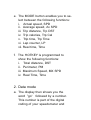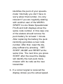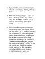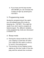
1
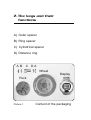
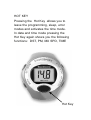
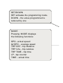
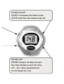
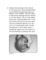
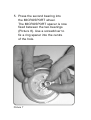
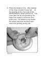
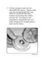
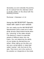
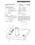
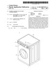
ENGLISH MICROSPORT ® In-Line Skate Speedometer PLUS Operating Instructions 1. Components of the MICROSPORT In-Line Skate Speedometer 2. The keys and their functions 3. Installation 3.1. Installing the wheel 3.2. Display and Perimeter 4. Operating the PLUS Speedometer 4.1. Operating the Display 5. Changing the Batteries 5.1. Changing the display battery 5.2. Changing the battery in the computer puck 6. Trouble Shooting 7. Remarks Important Information Thank you for choosing the MICROSPORT In-Line Skate Speedometer. This speedometer is recommended because of the easy installation and handling as well as its outstanding accuracy. Dont expose your Speedometer to direct sunlight for long periods and protect the display from extreme cold and hot temperatures. Handle your display carefully and keep it clean and dry. Before you start using your Speedometer please read this operating manual carefully. The actual installation procedure should take no longer than 10 minutes. Attention: 1. MICROSPORTs In-Line Skate Speedometer uses some small components which can be swallowed and can cause death by suffocation. 2. Always check your equipment before skating. Check the bearings and the fitting of the axle to avoid blocking or loosening of a wheel. 3. Skating accidents can always happen, even to experienced skaters. To avoid serious damage always wear the complete protective gear. 4. Skating needs the full attention of the skater, so dont let the MICROSPORT In-Line Skate Speedometer distract you from the traffic around you. 1. Components of the MICROSPORT In-Line Skate Speedometer Before you start please check the completeness of your speedometer package. Your speedometers consists of: a) A watch like display b) An orange wheel with a built in magnet c) A puck, housing the skate computer. The puck is approximately 1 cm high and has a 5 cm diameter d) Two kinds of spacers, one is cylindrical the other one looks like a thick ring. e) One additional distance ring f) Two outer spacers to fit the MICROSPORT wheel in wider frames. The different components of your speedometer are shown in picture 1. 2. The keys and their functions A) Outer spacer B) Ring spacer C) Cylindrical spacer D) Distance ring A B C DA Wheel Display Puck Picture 1 Content of the packaging HOT KEY Pressing the Hot Key allows you to leave the programming, sleep, error modes and activates the time mode. In data and time mode pressing the Hot Key again shows you the following functions: DST, PM, MX SPD, TIME Hot Key SET/DOWN SET activates the programming mode. DOWN - the value programmed is reduced by one MODE Pressing MODE displays the following functions: SPD - actual speed AV SPD - average speed TRP DST - trip distance TRP CAL - trip calories TRP TIME - trip time LP - lap counter TIME - actual time START/STOP START activates the data mode. STOP switches the data mode off. Hot Key RESET/UP RESET erases all data except the total distance and the time UP - the value programmed is increased by one. 3. Installation 3.1. Installing the wheel First you have to replace one of your current wheels with the MICROSPORT wheel. In principal it does not matter which wheel of your skates you replace, but we recommend that you chose the second or third wheel. This guarantees the best protection of you speedometer by the frame of your skate. Also we recommend you replace a wheel on the left skate if you want to wear the display on the right wrist and vice versa. Note: Please use adequate equipment to replace the wheel, eg. a special skate tool (not included in this package). 1. Disassemble the axle to replace the wheel. The wheel is normally fixed to the frame of your skates by two screws to the left and the right of the frame. These screws form the axle. While you turn out one screw keep an eye on the other screw as well. If the other screw begins to turn freely please hold it firm with you hand or another tool. Store the two screws carefully (Picture 2) for reassembling. Picture 2 2. Extract the bearings of the wheel. In the wheel you have disassembled you will find two bearings and one spacer in the middle. You now have to take these bearings and the spacer out of the wheel. This is most easily done with a special skate tool. If you dont have such a tool you can also use the cylindrical spacer (C in picture 1) in combination with a small screwdriver. If your skate uses a cylindrical spacer you can push out the first bearing by placing the cylin- Picture 3 drical MICROSPORT spacer on top of the original spacer (Picture 3) and pressing. The second bearing can then be pushed out from the inside (Picture 4). If your skate is operating with ring spacers (B in picture 1) put the screwdriver through the cylindrical MICROSPORT spacer and insert it almost halfway into the wheels hole intended for the axle. By bending the screwdriver to the side you can extract the first bearing. Again the second bearing can then be Picture 4 pushed out from the inside without problem. Store the bearings carefully. 3. Install the first of the bearings into the MICROSPORT wheel. Use your fingers to push one bearing into the hole of the orange MICROSPORT wheel (Picture 5). Picture 5 4. Place the correct spacer into the orange MICROSPORT wheel. Decide which of the MICROSPORT spacers you need. Principally if your original spacer looks cylindrical you will need the cylindrical MICROSPORT spacer. If your original spacer is a 1 cm thick ring you will need the 3 mm MICROSPORT ring spacer. Now place the MICROSPORT spacer into the MICROSPORT wheel (Pictures 6+7). Picture 6 5. Press the second bearing into the MICROSPORT wheel. The MICROSPORT spacer is now fixed between the two bearings (Picture 8). Use a screwdriver to fix a ring spacer into the centre of the hole. Picture 7 Picture 8 6. Place the distance ring (the smallest of the rings included in your kit) on the bearing of the inner side of the MICROSPORT wheel (Picture 9). The inner side can be recognised by the large hole ready to house the computer puck. The distance ring avoids the wheel and puck touching each other and grinding during use. Picture 9 7. Put the computer puck into the MICROSPORT wheel. Please make sure that the MICROSPORT logo which is a stylish M with transmission waves faces the outside (Picture 10). The wheel is now prepared for reassembly into your skate. Replace the complete wheel back into the frame. Picture 10 8. Stick the long axle screw through the frame and the MICROSPORT wheel and fix it with the second, smaller screw on the other side of the frame (Picture 11). Attention: If the wheel moves after tightening the screws in the direction of the axle, unscrew the axle one more time and place one or two of the Picture 11 outer spacers in front of the puck and behind the wheel to cover the spare space (Picture 12). Now the axle can be put in again. 9. Check that the puck does not turn with the wheel but keeps its fixed position while the wheel is spinning freely. Picture 12 You have completed the installation of the wheel. You do not need any technical skills for the further steps. In just two minutes you can start your first trip. 3.2. Display (wrist watch) and Perimeter The bracelet of the display is equipped with an elastic section under the actual watchcase which allows you to lengthen the bracelet. You can choose between wearing the display directly on the wrist or over the recommended wrist pads. Determining the perimeter of new wheels The following list helps you to find the perimeter of your wheel. Ø Ø Ø Ø Ø 72 74 76 78 80 mm mm mm mm mm <=> <=> <=> <=> <=> PM PM PM PM PM 226 232 239 245 251 mm mm mm mm mm Attention! The perimeter programmed into the display always has to correspond to the MICROSPORT wheel (the wheel size is printed on the packaging). The display in the packaging is preset to a 239 mm perimeter corresponding to a 76 mm diameter wheel. If you have bought your speedometer with a different wheel you have to adjust the perimeter in the programming mode before you start skating. Generally you can calculate the perimeter of a wheel from the diameter which is usually written on the wheel with the following formula: Perimeter = Diameter x 3,14 Using the MICROSPORT Speedometer with used or worn wheels You can easily use the MICROSPORT Speedometer with a used set of other skate wheels. Most skate brands allow the rockering of the skate wheels. This feature is meant to assemble wheels of different sizes into one frame. You can determine the ability of your skates by dismantling one wheel. When taking out the axle you can see a small plastic or metal part called washer with the hole for the axle. This hole is not in the centre of the washer so it depends on the instal- lation of the washer at which height the axle is built into the frame. If your MICROSPORT wheel is bigger than the others you have to built in the axle close to the boot. If your MICROSPORT wheel is smaller, the axle should be close to the ground. If rockering is not possible with your skates please use the next bigger MICROSPORT wheel. The extra exposure of this wheel will soon be worn down by the higher pressure on this wheel. The bigger size of the wheel does not effect the accuracy of the measurement. Make sure that you always program the perimeter of the MICROSPORT wheel in the display and not the perimeter of your other wheels. Adjusting the wear out function The MICROSPORT In-Line Skate Speedometers are equipped with an automatic wear out function. The computer takes into account the reduction of the wheel perimeter over time. This guarantees the accuracy of the measurement even if the wheels are already used. The built in wear out function is based on the statistical normal use of skates. The real perimeter reduction may differ individually due to the conditions of the ground usually skated on as well as the weight and technique of the skater. If you get the feeling that the displayed perimeter differs from the real perimeter, you should reprogram the watch with the actual value to guarantee the precision of the measurement. 4. Operating the PLUS Speedometer The PLUS version of the MICROSPORT In-Line Skate Speedometer has additional features such as a watch, a lapand a calorie-counter. These functions have to be programmed before usage. How to measure the actual perimeter of the wheel. To measure the actual perimeter of your wheel, make a dot on the outer surface of your MICROSPORT wheel. Start to roll your wheel over a piece of paper. Mark the paper where the dot of the wheel touches the paper. Go ahead rolling untill the dot touches the paper again. Mark this point again. The distance between the two marks is the required perimeter in [mm]. The calorie function is based on research of the University of Massachusetts. To improve the accuracy of the measurement MICROSPORT also integrates the number of skating steps in the individual calorie calculation. 1. Setting the perimeter To enter the programming mode press SET. The LCD displays the actual perimeter and the icon PM . The pre-programmed perimeter is 239 which is equivalent to a 76mm diameter wheel. The first digit of the perimeter is blinking. By pressing the UP and DOWN buttons you can switch to the correct value. Press MODE to confirm the programming. Proceed with the 2nd and 3rd digit as described above. After confirming the 3rd digit with MODE the display switches to the weight unit selection area. 2. You can chose between kilograms (kg) and pound (Lbs) for the unit of the weight. Press UP or DOWN to select the preferred value and confirm with MODE. 3. Enter your weight for the caloriecounter in the unit chosen before. This procedure is equivalent to the programming of the perimeter. Confirm each digit with the MODE button. 4. Select kilometres or miles After confirming the weight with MODE you can select between showing the results in kilometres (km) or miles (M). Switch between the units with the UP and DOWN buttons and confirm with MODE. 5. Time setting Finally you can program the watch. Please note that the time can only be programmed using the 24 hour clock, even when the time is displayed in am and pm during the usage of the speedometer. Switch to the correct values by pressing UP or DOWN and confirm each digit with MODE. The display is now programmed and the actual time will be displayed. If you have selected the weight unit to be pounds (Lbs) the time will be displayed in am and pm otherwise in 24 hour mode. Attention! If your weight is less than 100 kg (or 100 Lbs) please program a 0 for the first digit. For example 65 kg is equivalent to 065 kg. After confirming the last digit with MODE you can select between kilometres and miles. 4.1 Operating the PLUS Display The black, central button of the PLUS display will be referred to as HOTKEY. This chapter explains the usage and the effects of the different buttons of your PLUS Speedometer. In the PLUS version four different display modes can be separated (see next page). 1. Time mode You can use your PLUS Speedometer as a normal watch. Additionally you can browse through the d ifferent stored values of your last trip. 2. Data mode This mode has to be activated during skating to record your speed and distance information. 3. Programming mode You can set the wheel perimeter, weight and time. You can also select between the units of kilometres and miles as well as kilograms and pound. 4. Sleep mode Switches off the display. The values are stored and the watch works normally in the background. 1. Time mode a. The display shows the actual time. If you dont press any button for 2 hours the display automatically switches to sleep mode. b. The SET button activates the programming mode c. The START button activates the data mode d. The RESET button resets the internal buffer to zero for the following values: i. Average speed, Av SPD ii. Maximum speed, Mx SPD iii. Trip distance, Trp DST iv. Trip time, Trp Time v. Trip calories, Trp Cal vi. Lap counter, LP e. The MODE button enables you to select between the following functions: i. Actual speed, SPD ii. Average speed, Av SPD iii. Trip distance, Trp DST iv. Trip calories, Trp Cal v. Trip time, Trp Time vi. Lap counter, LP vii. Real time, Time f. The HOTKEY is programmed to show the following functions: i. Total distance, DST ii. Perimeter, PM iii. Maximum Speed, MX SPD iv. Real Time, Time 2. Data mode a. The display then shows you the word go followed by a number. This number is part of the digital coding of your speedometer and identifies the puck of your speedometer. Normally you dont have to worry about that number, it is only relevant if you are regularly skating with another user of the MICROSPORT In-Line Skate Speedometer PLUS and both displays show the same code number. In this case one of the skaters should remove his puck battery for at least 1 minute. After replacing the battery the puck randomly generates a new code number. After that, reset the display software by pressing SET, START, MODE and RESET at the same time. The next time you press START after the reset the display will identify the next puck transmission with its code as the new transmitter. b. If a correct signal is received the display shows you the actual speed. c. If you dont receive a correct signal after 10 seconds the display shows Err . d. While the display shows go or Err all other modes are frozen. Only the HOTKEY enables you to change immediately to the time mode. e. If the normal reception is interrupted (missing data) the display shows you the word Err until the connection is restored. If the missing data status lasts longer then 10 seconds the display changes to the time mode after pressing the HOTKEY. Please try to establish the connection again by pressing START. If you still cannot get the signal please check whether a) the display is correctly coded to your puck or b) the batteries are used up. f. During normal operation and data transmission the different buttons have the following functions: i. STOP -> Change to time mode. The actual function keeps being displayed. ii. SET -> Locked in the data mode iii. RESET -> Resets the internal buffer to zero. iv. MODE -> Shows you the following functions: SPD, Av SPD, Trp DST, Trp Cal, Trp Time, LP, Time v. HOTKEY -> Shows you the following functions: DST, PM, Mx SPD, Time Note: If the display does not reply to any of your inputs, reset the display software by pressing SET, START, MODE and RESET at the same time. This will reboot your display software. vi. If you have set the lap counter with MODE you can increase the number of laps by pressing the HOTKEY. 3. Programming mode During the programming of the watch you can always leave this mode by pressing the HOTKEY. This might be useful if you dont want to program all features again. The different variables in the programming mode are discussed in Section 3.2. 4. Sleep mode a. During the sleep mode the LCD of your display is switched off while your data and the watch continue to work in the background. b. The pushing of any display button wakes up the time mode of the display and the actual time is shown. Coding The In-Line Skate Speedometer PLUS has two independent coding techniques: a time code and a digital identification code. This code is set by putting in the puck battery. In order to link your display to your puck properly please take care that there is no other puck present (20 meters) when you activate the display for the first time. Turn the MICROSPORT wheel and press START. If you get a speed reading on the display afterwards the linking of the puck and the display was successful. If you get the Err message press SET, START, MODE and RESET simultaneously and start over again. If you have the feeling that you are getting the data of another skater on your display, you can change your puck code by taking out the puck battery for mode than one minute. When you reinstall the battery a new code is generated automatically. To finish the procedure you have to connect your display to the puck again. 5. Changing the batteries The lifespan of the display battery and the puck battery are the same. If you need to replace the batteries please always change both. The changing of the batteries and the speedometer maintenance is very easy with the MICROSPORT Battery Service Kit . It contains two CR 1632 batteries, o-rings and screws for maintaining the water resistance, a small screwdriver and an instruction manual. You can get the Battery Service Kit in your local sports store or directly from MICROSPORT at www.microsport.de 5.1. Changing the display battery Open the Watch Case Cover and carefully remove the old battery from the battery clip. Dismantle the isolator from the battery if present and attach it to the top (+) of the new battery. Insert the new battery of the type CR 1632 with + facing up and reinstall the battery clip. Close the back cover of the watch with the screws again. To check the successful installation press MODE. 5.2. Changing of the puck battery Remove the wheel from the frame according to your skate manual. Open the four screws of the puck with a small screwdriver. Open the case and remove the CR 1632 battery carefully. Insert the new battery with + facing up and replace cover in the correct position. Fix the cover with the screws. If you are using the Battery Service Kit for changing the batteries we recommend you replace the o-rings of the puck case as well. Also use the small o-rings provided for the screws to improved water resistance. 6. Troubleshooting Problem: Nothing appears on the display. Solution: Press MODE, if the display remains blank replace batteries of watch and electronic puck and press MODE again. Problem: Display readings fade out. Solution: Batteries of watch and elec- tronic puck are running out and have to be replaced. Problem: Slow display response. Solution: The current temperature is higher or lower than the operating temperature of the speedometer (0 °C to 55 °C/ 32 °F to 131 °F). Problem: Black display. Solution: Temperature is too high, perhaps the display has been exposed to direct sunlight for too long. Problem: Grinding of the electronic puck against the wheel. Solution: Your bearings are worn out. Replace bearings. We recommend at least ABEC-1 quality. Problem: The displayed actual speed seems to be unrealistic. Solution: A. The transmission may have been interrupted for a short time. Such an interruption has no significance for the accuracy of the measurement of the overall distance, as long as the interruption is for no longer than 1 kilometre. B. The pre-programmed average wearout function is not equivalent to the real usage of the wheels. Check the perimeter of the MICROSPORT wheel and correct the programming if necessary. C. Your bearings are either extremely good or extremely bad. In this case it can happen, that the skating software returns a distance differing from the real distance by more than 2%. By reprogramming the perimeter of the wheel you can adjust the software to your individual style and equipment. The new value for the perimeter is calculated as: real distance divided by shown distance mu ltiplied by the real perimeter. Problem: The communication between puck and display does not work. Solution: A. The transmitter in the puck is not activated jet. Turning the MICROSPORT wheel activates the transmitter after one turn. Check the connection by pressing START. B. The battery is weak so the distance between puck and display is to big. You can check by bringing puck and display close together and check again. If the signal is ok then you need to replace the batteries. C. The direction of the puck antenna needs to be optimised. The transmission quality can be influenced by the frame of the skates. Loosened the axle screw and turn the puck approx 30° fasten the screw again and check the transmission again. Go on until you have found the best antenna position. 7. Remarks You can get special spare parts and equipment for your MICROSPORT In-Line Skate Speedometer. The Battery Service Kit is a complete maintenance set. It consists of spare screws, new o-rings, a screwdriver, two batteries and an instruction manual, or you can get our Spare Wheels in one of the following sizes and density: 76mm/80A, 78mm/80A, 80mm/82A and 100mm/85A. If you have any other problems or questions please dont hesitate to call our international service at Munich, Germany: +49 89 307 255 99. Warranty MICROSPORT offers the original buyer of this In-Line Skate Speedometer the warranty corresponding to the laws in the country of purchase beginning from the date of the purchase for material and/or manufacturing errors. This warranty does not cover manual damage, damage during commercial usage, usual wear and tear, accident and faults arising from actions which ignore the warnings in this manual. The batteries are not covered by warranty. During the time of warranty MICROSPORT can repair or exchange bone fide claims. Please store the receipt carefully for evidence of purchase. Your MICROSPORT team hopes you enjoy this unique In-Line Skate Speedometer. Comments are always welcome. MICROSPORT GMBH & CO. KG GRÜNTAL 10A D-81925 MÜNCHEN GERMANY E-mail: [email protected] http://www.microsport.de The MICROSPORT In-Line Skate Speedometer fulfils the following requirements for devices in the EU and the USA: The devices comply with the requirements of ETS 300 683 Electro Magnetic Compatibility (EMC) standard for Short Range Devices (SRD) operating on frequencies between 9 kHz and 25 GHz. The devices comply with the requirements of EEC directive 89/336/EEC with regard to Electromagnetic Compatibility and fulfil the requirements of 99/5/EC with regard to Radio Equipment and Systems (RES); Electro Magnetic Compatibility (EMC) standard for Short Range Devices (SRD). FCC-ID: OWUOK622-7 The devices comply with Part 15 of the FCC rules. Operation is subject to the following two conditions: This device may not cause harmful interferences and this device must accept any interference received, including interference that may cause undesired operation.