1
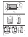
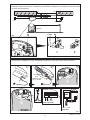
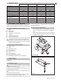
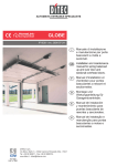
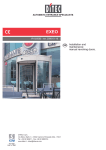
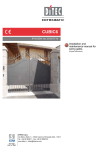
CROSS 5E-7E-7EH-8E
IP1747 - rev. 2005-12-06
DITEC S.p.A.
Via Mons. Banfi, 3 - 21042 Caronno Pertusella (VA) - ITALY
Tel. +39 02 963911 - Fax +39 02 9650314
www.ditec.it - [email protected]
I
Manuale di installazione
e manutenzione per
automazioni per cancelli
scorrevoli.
GB
Installation and
maintenance manual for
sliding gates automatic
system.
F
Manuel d’installation
et d’entretien pour
automatisme pour portails
coulissants.
D
Montage und
Wartungshandbuch
für Schiebtore
Automatisierung.
E
Manual para la instalaciòn
y la manutenciòn para
automatización para
cancelas de corredera.
P
Manual de instalação
e manutenção para
portaõ corrediço sistema
automatico.
Fig. 1
Fig. 2
Cross 5E - 7E - 8E
Cross 7EH
Fig. 3
CROSS5-7-8 - IP1747
2
Istallazione fotocellule all’interno del motoriduttore / Installing the photocells inside the geared motor / Installation de
photocellules dans le motoreducteur / Installation der photozellen im Getriebemotor / Instalacion de las fotocelulas
en el interior del motorreductor.
3.5x9.5
U
RX
U
Fig. 4
Istallazione LuxK7 all’interno del motoriduttore / Installing LuxK7 inside the geared motor / Installation LuxK7 dans
le motoreducteur / Installation LuxK7 im Getriebemotor / Instalacion LuxK7 en el interior del motorreductor.
1
3
2
Fig. 5
3
CROSS5-7-8 - IP1747
GB
manufacture of the motorised door);
draft the EC declaration of conformity in accordance with Annex
II-A of the Machinery Directive and deliver it to the customer;
- affix the CE marking on the power operated door in accordance with point 1.7.3 of Annex I of the Machinery Directive.
For more information consult the “Technical Manual Guidelines”
available on Internet at the following address: www.ditec.it
GENERAL SAFETY PRECAUTIONS
-
This installation manual is intended for professionally
competent personnel only.
Installation, electrical connections and adjustments must be
performed in accordance with Good Working Methods and in
compliance with applicable regulations.
Before installing the product, carefully read the instructions. Bad
installation could be hazardous.
The packaging materials (plastic, polystyrene, etc.) should not
be discarded in the environment or left within reach of children,
as these are a potential source of hazard.
Before installing the product, make sure it is in perfect condition.
Do not install the product in an explosive environment and atmosphere: gas or inflammable fumes are a serious hazard risk.
Before installing the motors, make all structural changes relating
to safety clearances and protection or segregation of all areas
where there is risk of being crushed, cut or dragged, and danger
areas in general.
Make sure the existing structure is up to standard in terms of
strength and stability.
The motor manufacturer is not responsible for failure to use
Good Working Methods in building the frames to be motorised
or for any deformation occurring during use.
The safety devices (photocells, safety edges, emergency stops,
etc.) must be installed taking into account: applicable laws and
directives, Good Working Methods, installation premises, system operating logic and the forces developed by the motorised
door or gate.
The safety devices must protect any areas where the risk exists
of being crushed, cut or gragged, or where there are any other
risks generated by the motorised door or gate. Apply hazard
area notices required by applicable regulations.
Each installation must clearly show the identification details of
the motorised door or gate.
Before making power connections, make sure the plate
details correspond to those of the power mains.
Fit an omnipolar disconnection switch with a contact opening
gap of at least 3 mm. Make sure an adequate residual current
circuit breaker and overcurrent cutout are fitted upstream of the
electrical system.
When necessary, connect the motorised door or gate to a reliable earth system made in accordance with applicable safety
regulations. During installation, maintenance and repair, interrupt
the power supply before opening the lid to access the electrical
parts.
To handle electronic parts, wear earthed antistatic conductive bracelets. The motor manufacturer declines all
responsibility in the event of component parts being fitted that
are not compatible with the safe an correct operation.
For repairs or replacements of products only original spare parts
must be used.
The installer shall provide all information relating to automatic,
manual and emergency operation of the motorised door or gate,
and provide the user with operating instructions.
APPLICATIONS
Service life: 3 (minimum 10÷5 years of working life with 30÷60
cycles a day)
Applications: FREQUENT (For vehicle or pedestrian accesses
to town houses or small condominiums with frequent use).
Service life: 4 (minimum 10÷5 years of working life with 100÷200
cycles a day).
Applications: HEAVY DUTY (For all special applications with
ongoing use such as toll gates and so on).
- Performance characteristics are to be understood as referring to
the recommended weight (approx. 2/3 of maximum permissible
weight). A reduction in performance is to be expected when the
access is made to operate at the maximum permissible weight.
- Service class, running times, and the number of consecutive
cycles are to be taken as merely indicative having been
statistically determined under average operating conditions, and
are therefore not necessarily applicable to specific conditions of
use. During given time spans product performance characteristics
will be such as not to require any special maintenance.
- The actual performance characteristics of each automatic
access may be affected by independent variables such as
friction, balancing and environmental factors, all of which
may substantially alter the performance characteristics of the
automatic access or curtail its working life or parts thereof
(including the automatic devices themselves). When setting
up, specific local conditions must be duly borne in mind and
the installation adapted accordingly for ensuring maximum
durability and trouble-free operation.
DECLARATION BY THE MANUFACTURER
(Directive 98/37/EC, Annex II, sub B)
Manufacturer:
DITEC S.p.A.
Address:
via Mons. Banfi, 3
21042 Caronno P.lla (VA) - ITALY
Herewith declares that the electromechanical automatic system
series Cross5E-7E-8E-7EH.
- is intended to be incorpored into machinery or to be assembled with other machinery to constitute machinery convered
by Directive 98/37/EC;
- is in conformity with the provisions of the following other EEC
directives: Electromagnetic Compatibility Directive 89/336/EEC;
Low Voltage Directive 73/23/EEC; and furthermore declares
that it is not allowed to put the machinery into service until
the machinery into which it is to be incorporated or of which
it is to be a component has been found and declared to be in
conformity with the provisions of Directive 98/37/EC and with
national implementing legislation.
Caronno Pertusella,
Fermo Bressanini
10-09-2003
(President)
MACHINERY DIRECTIVE
Pursuant to Machinery Directive (98/37/EC) the installer who
motorises a door or gate has the same obligations as the manufacturer of machinery and as such must:
- prepare the technical file which must contain the documents
indicated in Annex V of the Machinery Directive; (The technical file must be kept and placed at the disposal of competent
national authorities for at least ten years from the date of
CROSS5-7-8 - IP1747
10
1.
TECHNICAL DATA
Power supply
Absorption
Torque
Condenser
Max. run
Door speed
Max. door weight
Service class
Min. num. of consecutive cycles
Intermittence
Temperature
Degree of protection
Control panel
2.
GB
Cross5E
Cross7E
Cross7EH
Cross8E
230 V~ / 50 Hz
1,5 A
500 N
12,5 µF
20 m
0,18 m/s
400 kg
3 - FREQUENT
20
S2 = 15 min
S3 = 25%
-20 °C/+55 °C
IP24D
E1
230 V~ / 50 Hz
2A
700 N
16 µF
20 m
0,18 m/s
600 kg
4 - HEAVY DUTY
30
S2 = 20 min
S3 = 50%
-20 °C/+55 °C
IP24D
E1A
230 V~ / 50-60 Hz
1,5 A
600 N
20 m
0,12 ÷ 0,20 m/s
600 kg
4 - HEAVY DUTY
50
S2 = 30 min
S3 = 50%
-20 °C/+55 °C
IP24D
73RG
230 V~ / 50 Hz
3A
800 N
22 µF
20 m
0,18 m/s
800 kg
4 - HEAVY DUTY
30
S2 = 20 min
S3 = 50%
-20 °C/+55 °C
IP24D
E1A
any risk of cutting.
To reduce impact force installation of safety devices at gate
ends is recommended.
REFERENCE TO ILLUSTRATIONS
The given operating and performance features can only be guaranteed with the use of DITEC accessories and safety devices.
3.2 Base plate prearrangement
2.1 Standard installation references (fig. 1)
[1]
[2]
[3]
[4]
[5]
[6]
[7]
[8]
-
Radio
Flashing light
Key selector
Geared motor + electrical board
Photocells
Rubber hip / Sensitive hip
Opening and closing stop
Connect power supply to an omni-pole switch with a contact
opening gap of no less that 3 mm (not supplied by us).
Connection to supply mains must be carried out in an
independent raceway separate from control connections
and safety device connections.
-
First, insert the screws into the base plate blocking them
with a low nut [P], then, fold the tang to avoid displacement.
Take out the preformed wall anchors with a downward
movement and with the help of a hammer to ensure proper
anchorage to the concrete.
2.2 Geared motor references (fig. 3)
[9]
[10]
[11]
[12]
[13]
[14]
[15]
[16]
[17]
Geared motor
Carter
Manual lock release
Electrical board
Limit-switch spring
Pinion
Internal photocell
Courtesy light LUXK7 (optional)
BATK7 battery kit (optional, only for Cross7EH)
3.
INSTALLATION
Cross7E-7EH-8E
Unless otherwise specified, all measurements are expressed
in millimetres.
3.1 Preliminary checks
Check for gate stability (derailment and sideways falling),
that the slide wheels are in good condition and that the
top guides do not cause any friction.
The sliding track must be securely anchored to the ground and
fully exposed along its full length.
It must be perfectly smooth so as to avoid jamming of the
gate.
Provide opening and closing stops.
Note: make sure that the gate is securely inserted in the slideway
so that it cannot come out of the slideway and fall.
In case of slits being present on the gate, cover them to avoid
Cross5E
11
CROSS5-7-8 - IP1747
-
Lay a concrete foundation with buried anchoring brackets
and the base plate, making sure that it is perfectly level and
smooth (see figure).
Note: if the cement area is already present you can use the
adjustable SUPCS base.
Attention: the gearmotor must be suitably raised from the
ground to avoid flooding.
3.3 Geared motor installation
-
Release the gearmotor and remove the key. Loosen the
three frontal screws and remove the casing.
Position the gearmotor onto the base plate.
Gearmotor adjustments
Horizontally, by making it slide along the slots of the reduction
base, and vertically, with the four levelling screws [A].
Note: While adjusting vertically, keep the motor slightly
raised above the base plate so as to allow enough space to
secure the rack and to make any subsequent adjustments,
if necessary.
(*) CROSS CRI
X = 40 mm
(*) CROSS CRN
X = 40 mm
(**) CROSS7EHTC
3.4 Rack installation
-
-
-
Release the gearmotor and set the gate in the open position. Place the rack on pinion [14] and move the gate
manually to secure the rack along its full length.
Once the rack has been secured, vertically adjust the
geared motor so as to have a gap of 2 to 3 mm between
the pinion and the rack with screws [A].
Firmly secure the gearmotor by means of nuts [F].
Lubricate the rack and pinion lightly after assembly. Manually move gate to check that it slides freely and smoothly.
Cross7E-7EH-8E
GB
Cross5E
CROSS5-7-8 - IP1747
12
3.5 Adjusting limit switch
3.7 Cross7EHTC installation (only for Cross7EH)
-
Disengage the gearmotor (see OPERATING INSTRUCTIONS).
Remove the pinion [14]. Fix the pinion-holding plate to the
gearmotor. Fit the pinions as shown in the figure. Manually route
the chain through the pinions. Fix the cover plate.
Attention: with chain fitted, the gearmotor direction of rotation
is reversed.
Manually position the door wing completely open and fasten
the limit switch brackets [L] onto the rack so that the lever
limit switch exceeds the bracket’s length by approximately
2/3. Repeat the operation with door wing completely closed.
After having performed a certain number of operations,
adjust the position of the limit switch bracket [L] so that the
gate will stop about 20 mm before the opening and closing
stops.
Note: (Only for Cross7EH) the limit switch kit is optional and it is
used to stop the gate before the opening and closing stops.
When limit switch is present, slow down is carried out at
maximum power to overcome possible friction.
3.8 Chain installation
Set the gate in the open position and fasten brackets [G]
to the wing as shown in figure.
-
-
-
Connect the chain previously installed on the gearmotor to
the tie rod [H] and fasten it to the bracket [G].
Secure the bracket [G] onto the opposite side of the gate.
Connect the chain to the tie rod [H] and secure it to the
bracket [G] (cut off excess chain).
Note: with the gate in complete opening and closing position, check that the distance between the centre of the
pinion [Y] and the tie rod [H] shown in figue is respected.
3.6 Operation by encoder
The Cross7EH does not require limit switches because it has an
encoder. Stops must necessarily be installed. The gate decelerates automatically in proximity of the stops.
Attention: upon reaching the opening or closing limit stop, the
gate performs a brief disengaging maneuver (moving reversal)
to facilitate the manual release of the geared motor.
-
13
Finally, firmly secure the gearmotor by means of nuts [D].
Tighten the chain by means of tie rods [H].
Lightly lubricate the chain and pinion after assembly.
CROSS5-7-8 - IP1747
GB
GB
4.
ELECTRICAL CONNECTION
7.
Electrical wiring and starting are shown in the installation
manual of control panel E1-E1A (Cross5E-7E-8E) and 73RG
(Cross7EH).
230 V cables (power supply, flashing light and external courtesy
light, if any) are to be positioned on the right of the electric control
panel, as it is shown in the figure.
24 V cables (safeties, controls and external antenna, if any) are
to be positioned on the left of the electric control panel, as it is
shown in the figure.
ATTENTION: Connect the yellow-green ground cable to the
clamp already connected to the motor, as it is shown in the figure.
BATK7 [17] BATTERY KIT INSTALLATION
(only Cross7EH)
The BATK7 battery kit permits to operate the gate even in case
of mains power failure.
Note: when not in use, batteries are kept charged by means of
the control circuit.
Fit the batteries inside the geared motor and secure by means of
the appropriate support brackets (see instructions of BatK7).
8.
MAINTENANCE PROGRAM (each 6 month)
Power off and geared motor released (see OPERATING INSTRUCTIONS):
- Visually check that the gate, anchoring bracket and existing
structure are sufficiently sturdy and in good condition.
- Check gate/gearmotor alignment and the distance (2-3 mm)
between the mouth of the pinion and the crest of the rack and
check the distance from the rack to the rack guide bracket
(3 mm), if fitted.
- Clean the wheel sliding tracks, lightly lubricate the pinion,
the rack or the chain. Manually move gate to check that it
slides freely and smoothly.
Power on and geared motor lock (see OPERATING INSTRUCTIONS):
- Check the functioning of the limit switches (the gate must
come to a halt about 20 mm before the stops).
- Check the power adjustments.
- Check the operation of all controls and safety functions.
ATTENTION: For spare parts, see the spares price list.
5.
INSTALLING THE PHOTOCELLS INSIDE THE
GEARED MOTOR (fig. 4)
Additional photocells may be installed inside the gearmotor for
the protection of both opening and closing movement. Fit a receiver (RX) or a transmitter (TX) on the [U] brackets provided.
Installation of the photocells must be carried out in observance
of the standards EN 12453 and EN 12445.
Attention: the photocell receiver (RX) and transmitter (TX) may
also be installed at two different heights, the maximum permissible difference in height being 300 mm.
6.
INSTALLING LUXK7 INSIDE THE GEARED
MOTOR (fig. 5)
The courtesy lamp can be mounted inside the gear motor. For
mounting and connection, carry out the operations shown in
the figure.
ATTENTION: Connect the yellow-green ground cable to the
clamp already connected to the motor, as it is shown in the
figure.
The courtesy lamp can be enabled or disabled by means of a
BixLP4 radio remote control and by storing the CH3 function
(see instructions E1A, 73RG).
All right reserved
All data and specifications have been drawn up and checked
with the greatest care. The manufacturer cannot however take
any responsibility for eventual errors, ommisions or incomplete
data due to technical or illustrative purposes.
CROSS5-7-8 - IP1747
14
OPERATING INSTRUCTION FOR SLIDING GATES CROSS5E-7E-7EH-8E
RELEASE INSTRUCTION
In case of fault or power failure, insert and turn the key
anticlockwise, completely open the cover. Manually open
the gate. To lock the gate again, shut the cover, turn the key
clockwise and remove the key.
Attention: perform locking and lock release operations
with motor cut off.
Attention: with the cover closed and the key in a horizontal
position, the lock release microswitch is open, thus preventing
any operation.
TEAR OFF AND DELIVER TO USER
GENERAL SAFETY PRECAUTIONS
The following precautions are an integral and essential part
of the product and must be supplied to the user.
Read them carefully as they contain important indications for
the safe installation, use and maintenace.
These instruction must be kept and forwarded to all possible
future user of the system.
This product must be used only for that which it has been expressely designed.
Any other use is to be considered improper and therefore dangerous.
The manufacturer cannot be held responsible for possible damage caused by improper, erroneous or unresonable use.
Avoid operating in the proximity of the hinges or moving mechanical parts.
Do not enter the field of action of the motorised door or gate
while in motion.
Do not obstruct the motion of the motorised door or gate as this
may cause a situation of danger.
Do not lean against or hang on to the barrier when it is moving.
Do not allow children to play or stay within the field of action of
the motorised door or gate.
Keep remote control or any other control devices out of the reach
of children, in order to avoid possible involuntary activation of
the motorised door or gate.
In case of breack down or malfunctioning of the product, disconnect from mains, do not attempt to repair or intervene directly
and contact only qualified personnel.
Failure to comply with the above may create a situation of
danger.
All cleaning, maintenance or repair work must be carried out by
qualified personnel.
In order to guarantee that the system works efficiently and
correctly it is indispensable to comply with the manufacturer’s
indications thus having the periodic maintenance of the motorised door or gate carried out by qualified personnel.
In particular regular checks are recommended in order to verify
that the safety devices are operating correctly. All installation,
maintenance and repair work must be documented and made
available to the user.
Installator:
DITEC S.p.A.
Via Mons. Banfi, 3
21042 Caronno Pertusella (VA) - ITALY
Tel. +39 02 963911 - Fax +39 02 9650314
www.ditec.it - [email protected]