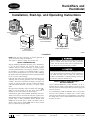
1
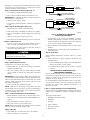
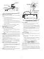
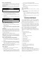
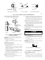
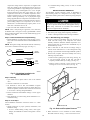
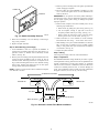
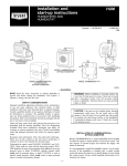
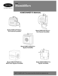
Humidifiers and
Humidistat
Visit www.carrier.com
Installation, Start-Up, and Operating Instructions
MODEL HUMCCLFP1025-A-FAN-POWERED
HUMIDIFIER
MODEL HUMCCSFP1016-A-FAN-POWERED
HUMIDIFIER
MODEL HUMCCLBP2018-A-BYPASS HUMIDIFIER
MODEL HUMCCSBP2017-A--
MODEL HUMCCWTR2019-A-WATER-SAVER
BYPASS HUMIDIFIER
A98362
→ Humidifiers
NOTE: Read the entire instruction in manual applicable to
specific unit before starting the installation.
This symbol → indicates a change since the last issue.
SAFETY CONSIDERATIONS
Improper installation, adjustment, alteration, service, maintenance,
or use can cause explosion, fire, electrical shock, or other
conditions which may cause personal injury or property damage.
Consult a qualified installer, service agency, distributor, or branch
for information or assistance. The qualified installer or agency
must use factory-authorized kits or accessories when modifying
this product. Refer to the individual instructions packaged with the
kits or accessories when installing.
Follow all safety codes. Wear safety glasses and work gloves. Use
quenching cloth for brazing operations. Have fire extinguisher
available. Read these instructions thoroughly and follow all
warnings or cautions attached to the unit. Consult local building
codes and National Electrical Code (NEC) for special requirements.
Recognize safety information. This is the safety-alert symbol
.
When you see this symbol on the unit and in instructions or
manuals, be alert to the potential for personal injury.
Understand the signal words DANGER, WARNING, and CAUTION. These words are used with the safety-alert symbol. DANGER identifies the most serious hazards which will result in severe
personal injury or death. WARNING signifies hazards which
could result in personal injury or death. CAUTION is used to
identify unsafe practices which would result in minor personal
injury or product and property damage.
Before installing or servicing system, always turn off main
power to system. There may be more than 1 disconnect
switch. Turn off accessory heater power if applicable. Electrical shock can cause personal injury or death.
Unit must not be installed where freezing temperatures could
occur. Do not install unit on the furnace or fan coil jacket. Do
not install unit where ends of cooling coil could restrict
airflow to the humidifier. Condensation damage could occur
if home has closed-off, unheated rooms.
INSTALLATION OF HUMCCLBP2018-A-BYPASS HUMIDIFIER
Carrier’s HUMCCLBP2018-A-- bypass humidifier can be installed on either the supply or return plenum of a forced-air system.
This unit requires an external bypass duct between the supply- and
return-air ductwork.
It is recommended to install the humidifier where it can be easily
serviced. If this humidifier is installed with a central cooling
system the bypass duct must have a shutoff damper to close during
the cooling season. Always install humidifier downstream of an
electronic air cleaner.
Manufacturer reserves the right to discontinue, or change at any time, specifications or designs without notice and without incurring obligations.
Book 1 4
PC 101
Catalog No. 03HU-MC1
Printed in U.S.A.
Form HUM-1SI
Pg 1
7-98
Replaces: 49-4SI
Tab 7a 9a
→ Step 1—Inspect Package and Check Equipment
Inspect contents of packaged humidifier. File claim with shipping
company prior to installation if shipment is damaged or incomplete.
The package should contain:
TEMPLATE
1. Humidifier and media assembly
PLENUM
2. Humidistat
LEVEL
3. Template
4. Owner’s Manual
5. Warranty Certificate
6. Solenoid valve with bridge rectifier
7. Saddle valve assembly with adapter
A97096
8. Four sheet metal screws
Fig. 2—Preparing Plenum Opening
9. Foam tape
10. Water noise reducer (use for water pressure over 60 psi)
FOAM TAPE
11. 6-in. damper
SCREWS
12. Worm clamp for field-supplied drain tube
13. Humidifier maintenance instruction sticker
14. Carrier logo label
BYPASS UNITS
"N" COIL
NOTCH
A98364
→ Fig. 3—Mounting the Humidifier
DRILL (2) HOLES
IN DUCT
FOR #8 SHEETMETAL
SCREWS
Step 4—Mount the Humidifier (See Fig. 3.)
1. Attach foam tape on inside of mounting flange.
2. Hook bottom notch of humidifier on opening cut in plenum.
3. Push top of humidifier to plenum aligning screw holes with
flange.
4. Align, level, and secure using top screws first.
5. Insert bottom screws and tighten all screws for air tight seal.
→ Step 5—Install Bypass Duct
BYPASS UNITS ONLY
HORIZONTAL
Attach field-supplied 6-in. diameter duct, elbow, or starting collar
with field-supplied 1/4-in. zip screws. Install supplied 6-in. damper
in 6-in. duct connector.
VERTICAL
A98363
IMPORTANT: On systems with central cooling, the damper
should be closed during cooling season to prevent bypass air.
→ Fig. 1—Installation of HUMCCLBP2018-A-Bypass-Type Humidifier
Step 2—Select Location (See Fig. 1.)
Do not support weight of bypass duct from humidifier —
damage could result.
Humidifier may be installed on either supply or return plenum.
If furnace has air conditioning coil, be sure humidifier does not
interfere with coil ends. Remember to provide clearance for
maintenance and evaporator pad removal.
Step 6—Install Drain Line
→
Step 3—Prepare Plenum Opening (See Fig. 2.)
1. Use template for marking humidifier opening.
1. Use 1/2- or 5/8-in. vinyl tubing (field supplied) to connect
drain on bottom of humidifier housing to an open drain.
2. Use supplied worm clamp to hold drain tubing in position over
drain fitting outlet.
2. Tape in place on plenum making sure template is level.
IMPORTANT: For humidifier to operate properly it must be level
and mounted on a vertical surface.
Unit may leak if drain tubing is misapplied. Do not insert
tubing inside of drain fitting outlet.
3. Drill four 1/8-in. holes in plenum.
4. Cut opening in plenum using heavy solid lines on template as
a guide.
3. Make sure line is free of traps due to sagging and has
sufficient pitch to drain.
2
HUMIDIFIER
1. Inform homeowner of proper operation, maintenance, and
humidistat setting.
HUMIDISTAT
BROWN
24VAC
FURNACE
BROWN
a. If unit is installed during cooling season, close bypass
damper, set humidistat for summer setting (OFF or lowest
setting).
b. If installed during heating season, set unit for normal
operation.
TRANSFORMER
HUMIDISTAT (FIELD SUPPLIED)
HUMIDIFIER
RED
BLU
24V
INSTALLATION OF HUMCCLFP1025-A-FAN POWERED HUMIDIFIER
115V
FIELD
WIRING
Carrier’s HUMCCLFP1025-A-- fan powered humidifier can only
be installed on the supply plenum of a forced-air system. This unit
requires an external 115-vac (fused) plug-in receptacle near the
equipment for proper operation.
It is recommended to install the humidifier where it can be easily
serviced. Pad access can be easily obtained from either the top or
bottom of unit. Always install humidifier downstream of an
electronic air cleaner.
A98365
→ Fig. 4—Installation of Humidistat
on Bypass-Type Humidifier
→ Step 1—Inspect Package and Check Equipment
Step 7—Make Water Connection
Inspect the contents of packaged humidifier. File claim with
shipping company prior to installation if shipment is damaged or
incomplete.
The package should contain:
If garden hose is not used for water supply:
1. Mount saddle valve on water line according to instructions
supplied with valve.
2. Run 1/4-in. diameter (water line grade) tubing from saddle
valve to adapter on solenoid valve and tighten compression
fittings.
1. Humidifier and media assembly
2. Humidistat
3. Template
IMPORTANT: If water pressure is higher than normal (60 psi),
use noise suppression disk included in parts bag. (Read water noise
reducer note located inside package for instructions.) For normal
operation, saddle valve need only be opened 1 full turn to meet
performance requirements.
4. Owner’s Manual
5. Warranty Certificate
6. Solenoid valve
7. Saddle valve assembly with adapter
3. Open valve and check installation for leaks.
→
8. Four sheet metal screws
NOTE: Saddle valve is self piercing on copper lines; 1/4-in. hole
must be drilled in steel or iron pipes. Use only a grounded drill or
a hand drill to avoid shock hazard. Turn off water and drain the
pipe prior to drilling 1/4-in. hole.
10. Water noise reducer (use for water pressure over 60 psi)
Step 8—Install Humidistat and Complete Wiring
12. Humidifier maintenance instruction sticker
9. Foam tape
11. Worm clamp for field-supplied drain tube
1. Mount humidistat on inside wall, or return-air duct in accordance with section INSTALLATION OF HUMIDISTAT on
page 10.
13. Carrier logo label
RED
2. Wire brown low voltage leads to furnace control board, or
install a field-supplied step-down transformer 115vac/24vac
60Hz to power solenoid valve. (See Fig. 4.) Make sure bridge
rectifier is attached to coil of solenoid valve.
"N" COIL
BLUE
NOTE: Wiring must comply with National Electrical Code and
any local codes or ordinances that may apply.
Step 9—Start-Up
1. Open saddle valve to permit water flow to the solenoid.
2. Check all connections for water leaks.
3. Set thermostat to call for heat. Set humidistat for highest
humidity setting making sure contacts are closed. After a few
minutes of operation, check the drain connection for leaks and
to see if water is flowing through humidifier.
VERTICAL
4. Reverse thermostat and humidistat settings to insure proper
shutdown.
HORIZONTAL
A98366
→ Fig. 5—Installation of HUMCCLFP1025-A-Fan-Type Humidifier
5. Reset thermostat to normal setting. Reset humidistat to recommended setting.
Step 2—Select Location (See Fig. 5.)
Step 10—Final Steps
Humidifier must be installed on supply plenum only. If furnace has
air conditioning coil, be sure humidifier does not interfere with coil
ends.
Attach humidifier maintenance instruction sticker to a visible
location.
3
Remember to provide clearance for maintenance and evaporator
pad removal. To access pad remove top or bottom cover to expose
assembly (turn knob counter-clockwise).
HUMIDIFIER
HUMIDISTAT
RED
24VAC
FURNACE
BLU
Step 3—Prepare Plenum Opening (See Fig. 2.)
1. Use template for marking humidifier opening.
115V FIELD WIRING
FAN TYPE UNITS ONLY
2. Tape in place on plenum making sure template is level.
IMPORTANT: For humidifier to operate properly it must be level
and mounted on a vertical surface.
TRANSFORMER
HUMIDISTAT (FIELD SUPPLIED)
HUMIDIFIER
3. Drill four 1/8-in. holes in plenum.
RED
4. Cut opening in plenum using heavy solid lines on template as
a guide.
BLU
Step 4—Mount the Humidifier (See Fig. 3.)
24V
115V
FIELD
WIRING
115V FIELD WIRING
FAN TYPE UNITS ONLY
1. Attach foam tape on inside of mounting flange.
2. Hook bottom notch of humidifier on opening cut in plenum.
A96010
3. Push top of humidifier to plenum aligning screw holes with
flange.
Fig. 6—Installation of Humidistat
on Fan-Type Humidifier
4. Align, level, and secure using top screws first.
3. Set thermostat to call for heat. Set humidistat for highest
humidity setting making sure contacts are closed. After a few
minutes of operation, check the drain connection for leaks and
to see if water is flowing through humidifier.
5. Insert bottom screws and tighten all screws for air tight seal.
→ Step 5—Install Drain Line
1. Use 1/2- or 5/8-in. vinyl tubing (field supplied) to connect
drain on bottom of humidifier housing to an open drain.
4. Reverse thermostat and humidistat settings to insure proper
shutdown.
2. Use supplied worm drain clamp to hold drain tubing in
position over drain fitting outlet.
5. Reset thermostat to normal setting. Reset humidistat to recommended setting.
Step 9—Final Steps
Unit may leak if drain tubing is misapplied. Do not insert
tubing inside of drain fitting outlet.
Attach humidifier maintenance instruction sticker to a visible
location.
3. Make sure line is free of traps due to sagging and has
sufficient pitch to drain.
1. Inform homeowner of proper operation, maintenance, and
humidistat setting.
Step 6—Make Water Connection
a. If unit is installed during cooling season set humidistat for
summer setting (OFF or lowest setting).
If garden hose is not used for water supply:
1. Mount saddle valve on water line according to instructions
supplied with saddle valve.
b. If installed during heating season, set unit for normal
operation.
2. Run 1/4-in. diameter (water line grade) tubing from saddle
valve to adapter on solenoid valve and tighten compression
fittings.
INSTALLATION OF HUMCCSFP1016-A-FAN POWERED HUMIDIFIER
Carrier’s HUMCCSFP1016-A-- fan powered humidifier can only
be installed on the supply plenum of a forced-air system. This unit
requires an external 115-vac (fused) plug-in receptacle near the
equipment for proper operation.
IMPORTANT: If water pressure is higher than normal (60 psi),
use noise suppression disk included in parts bag. (Read water noise
reducer note located inside package for instructions). For normal
operation, saddle valve need only be opened 1 full turn to meet
performance requirements.
It is recommended to install the humidifier where it can be easily
serviced. Pad access door can be easily converted from right to the
left hand side. Always install humidifier downstream of an
electronic air cleaner.
3. Open valve and check installation for leaks.
NOTE: Saddle valve is self piercing on copper lines; 1/4-in. hole
must be drilled in steel or iron pipes. Use only a grounded drill or
a hand drill to avoid shock hazard. Turn off water and drain the
pipe prior to drilling 1/4-in. hole.
→ Step 1—Inspect Package and Check Equipment
Inspect contents of packaged humidifier. File claim with shipping
company prior to installation, if shipment is damaged or incomplete.
Step 7—Install Humidistat and Complete Wiring
The package should contain:
1. Mount humidistat on inside wall, or return-air duct in accordance with section INSTALLATION OF HUMIDISTAT on
page 10.
1. Humidifier and media assembly
2. Humidistat
2. Wire red and blue low voltage. (See Fig. 6.)
3. Template
3. Plug power cord in to 115-vac 60Hz source.
NOTE: Wiring must comply with National Electrical Code and
any local codes or ordinances that may apply.
4. Owner’s Manual
5. Warranty Certificate
6. Solenoid valve
Step 8—Start-Up
1. Open saddle valve to permit water flow to the solenoid.
2. Check all connections for water leaks.
4
7. Saddle valve assembly with adapter
8. Four sheet metal screws
9. Foam tape
10. Noise suppressor (use for water pressure over 60 psi)
11. Worm clamp for field-supplied drain tube
12. Humidifier maintenance instruction sticker
13. Carrier logo label
"N" COIL
HORIZONTAL
A96049
VERTICAL
Fig. 8—Reversing Door Access
on HUMCCSFP1016-A--
HORIZONTAL
MEDIA PAD
ASSEMBLY
DRAIN
OUTLET
A97098
Fig. 7—Installation of HUMCCSFP1016-A-Fan-Type Humidifier
HOUSING
ENCLOSURE
Step 2— Select Location (See Fig. 7.)
Humidifier must be installed on supply plenum only. If furnace has
air conditioning coil, be sure humidifier does not interfere with coil
ends. Remember to provide clearance for maintenance and evaporator pad removal.
To reverse pad access from right to the left side:
VINYL DRAIN
TUBING
DRAIN OUTLET
A97108
Fig. 9—Media Pad Assembly Installation
IMPORTANT: For humidifier to operate properly it must be level
and mounted on a vertical surface.
3. Drill four 1/8-in. holes in plenum.
4. Cut opening in plenum using heavy solid lines on template as
a guide.
Step 4—Mount the Humidifier
1. Attach foam tape to back of mounting flange (exclude the
off-set edge).
2. Hook off-set edge over opening cut in plenum.
3. Place humidifier in plenum aligning screw holes with flange.
4. Align, level, and tighten all screws for air tight seal.
Step 5—Install Drain Line
1. Use 5/8-in. vinyl tubing (field supplied) to connect drain on
bottom of humidifier housing to an open drain.
2. Use clamp to hold drain tubing in position over drain fitting
outlet.
1. Remove side door and media pad assembly.
2. Remove 4 screws and separate top assembly from lower
mounting base. (See Fig. 8.)
3. Rotate lower mounting base 180 degrees, so side access door
is now on left.
4. Snap together top assembly to mounting base and reinstall
screws.
5. Replace media pad assembly (with distributor reservoir up)
and side access door.
When re-installing media pad assembly into plastic housing,
insure the assembly drain stub aligns into the drain outlet
located in bottom of humidifier. Unit can leak if drain stub
does not align with drain outlet. (See Fig. 9.)
IMPORTANT: Make sure front housing assembly with electrical
cord is facing down.
Unit may leak if drain tubing is misapplied. Do not insert
tubing inside of drain fitting outlet.
Step 3—Prepare Plenum Opening (See Fig. 2.)
1. Use template for marking humidifier opening.
3. Make sure line is free of traps due to sagging and has
sufficient pitch to drain.
2. Tape in place on plenum making sure template is level.
5
SOLENOID
VALVE
TUBING
ENCLOSURE
INLET HOLE
INLET HOLE
HOUSING
ENCLOSURE
SEAT
SOLENOID
VALVE
FLUSH
AGAINST
INLET
POSITION TUBING
INSIDE INLET HOLE
(CUT LENGTH
IF REQUIRED)
A97107
Fig. 10—Top Mounting of Water Solenoid Valve
Step 6—Mount Solenoid Valve
The water solenoid valve should be mounted on top of humidifier
enclosure.
1. To mount solenoid on top, see Fig. 10.
a. Firmly press valve into the top inlet hole on enclosure. Seat
valve flush against inlet hole.
A97099
Fig. 11—Alternate Mounting of Solenoid Valve
on HUMCCSFP1016-A-- Humidifier
2. If alternate mounting of solenoid is required, see Fig. 11.
a. To mount solenoid on side, use 3/8-in. ID, 1/2-in. OD vinyl
tubing (field supplied). Place tubing onto valve stem and
secure with clamp.
Step 9—Start-Up
1. Open saddle valve to permit water flow to the solenoid.
b. Mount valve upside down securing to side of housing.
2. Check all connections for water leaks.
c. Place open end of tubing into the top inlet hole.
3. Set thermostat to call for heat. Set humidistat for highest
humidity setting making sure contacts are closed. After a few
minutes of operation, check the drain connection for leaks and
to see if water is flowing through humidifier.
IMPORTANT: Be careful not to kink tubing.
Step 7—Make Water Connection
If garden hose is not used for water supply:
4. Reverse thermostat and humidistat settings to insure proper
shutdown.
1. Mount saddle valve on water line according to instructions
supplied with valve.
5. Reset thermostat to normal setting. Reset humidistat to recommended setting.
2. Run 1/4-in. diameter (water line grade) tubing from saddle
valve to adapter on solenoid valve and tighten compression
fittings.
Step 10—Final Steps
Attach humidifier maintenance instruction sticker to a visible
location.
IMPORTANT: If water pressure is higher than normal (60 psi),
use noise suppression disk included in parts bag. (Read water noise
reducer note located inside package for instructions). For normal
operation, saddle valve need only be opened 1 full turn to meet
performance requirements.
1. Inform homeowner of proper operation, maintenance, and
humidistat setting.
a. If unit is installed during cooling season set humidistat for
summer setting (OFF or lowest setting).
3. Open valve and check installation for leaks.
NOTE: Saddle valve is self piercing on copper lines; 1/4-in. hole
must be drilled in steel or iron pipes. Use only a grounded drill or
a hand drill to avoid shock hazard. Turn off water and drain the
pipe prior to drilling 1/4-in. hole.
b. If installed during heating season, set unit for normal
operation.
INSTALLATION OF HUMCCSBP2017-A-BYPASS HUMIDIFIER
Carrier’s HUMCCSBP2017-A-- bypass humidifier can be installed on either the supply or return plenum of a forced air system.
This unit requires an external bypass duct between the supply- and
return-air ductwork.
Step 8—Install Humidistat and Complete Wiring
1. Mount humidistat on inside wall, or return-air duct in accordance with section INSTALLATION OF HUMIDISTAT on
page 10.
It is recommended to install the humidifier where it can be easily
serviced. If this humidifier is installed with a central cooling
system the bypass duct must have a shutoff damper to close during
the cooling season. Always install humidifier downstream of an
electronic air cleaner.
2. Wire red and blue low-voltage leads. (See Fig. 6.)
3. Plug power cord in to 115-vac 60Hz source.
NOTE: Wiring must comply with National Electrical Code and
any local codes or ordinances that may apply.
6
→ Step 1—Inspect Package and Check Equipment
Step 3—Prepare Plenum Opening (See Fig. 2.)
1. Use template for marking humidifier opening.
2. Tape in place on plenum making sure template is level.
IMPORTANT: For humidifier to operate properly it must be level
and mounted on a vertical surface.
3. Drill four 1/8-in. holes in plenum.
Inspect the contents of packaged humidifier. File claim with
shipping company prior to installation if shipment is damaged or
incomplete.
The package should contain:
1. Humidifier and media assembly
SOLENOID
VALVE
ASSEMBLY
2. Humidistat
BROWN
3. Template
4. 6-in. damper
5. Owner’s Manual
6. Warranty Certificate
7. Solenoid valve with bridge rectifier
8. Transfer tube
9. Saddle valve assembly with adapter
10. Three pair of miscellaneous screws
11. Six sheet metal screws
12. Foam tape
13. Water noise reducer (use for water pressure over 60 psi)
14. Worm clamp for field-supplied drain tube
15. Humidifier maintenance instruction sticker
16. Carrier logo label
PAD
ACCESS
DOOR
BYPASS UNITS
A98368
→ Fig. 13—Mounting Solenoid Valve
on HUMCCSBP2017-A-- Humidifier
"N" COIL
4. Cut opening in plenum using heavy solid lines on template as
a guide.
Step 4—Mount Humidifier
1. Attach foam tape on inside of mounting flange.
2. Determine discharge direction.
3. If right-hand discharge is required:
a. Remove side door and media pad assembly.
b. Invert unit 180 degrees.
c. Re-install media pad and door.
IMPORTANT: Always ensure pad assembly is in the upright
position.
4. Attach solenoid valve to unit housing using two screws in
upper mounting holes. (See Fig. 13.) Do not over tighten
screws.
5. Attach transfer tube to solenoid valve and insert free end into
inlet fitting on top of unit housing.
6. Attach bridge rectifier to solenoid valve.
7. Insert sheet metal screws into lower holes in plenum, predrilled using template.
8. Tighten screws until heads protrude approximately 3/16-in.
9. Hang humidifier on bottom screws and push top of humidifier
to plenum, aligning top screw holes with flange, and insert
screws.
10. Align and level unit.
11. Tighten all screws for air tight seal.
ACCESS
DOOR
DRILL (2) HOLES
IN DUCT
FOR #8 SHEETMETAL
SCREWS
VERTICAL
HORIZONTAL
A98367
→ Fig. 12—Installation of
HUMCCSBP2017-A-Bypass-Type Humidifier
Step 2—Select Location (See Fig. 12.)
Humidifier may be installed on either supply or return plenum. If
furnace has air conditioning coil, be sure unit does not interfere
with coil ends. Remember to provide clearance for maintenance
and evaporator pad removal.
7
→ Step 5—Install Bypass Duct
to see if water is flowing through humidifier.
Attach field-supplied 6-in. diameter duct, elbow, or starting collar
with field-supplied 1/4-in. zip screws. Install supplied 6-in. damper
in 6-in. duct connector.
4. Reverse thermostat and humidistat settings to insure proper
shutdown.
5. Reset thermostat to normal setting. Reset humidistat to recommended setting.
IMPORTANT: On systems with central cooling, the damper
should be closed during cooling season to prevent bypass air.
Step 10—Final Steps
Attach humidifier maintenance instruction sticker to a visible
location.
Do not support weight of bypass duct from humidifier —
damage could result.
1. Inform homeowner of proper operation, maintenance, and
humidistat setting.
Step 6—Install Drain Line
→
a. If unit is installed during cooling season, close bypass
damper, set humidistat for summer setting (OFF or lowest
setting).
1. Use 5/8-in. ID vinyl tubing (field supplied) to connect drain on
bottom of humidifier housing to an open drain.
2. Use worm clamp to hold drain tubing in position over drain
fitting outlet.
b. If installed during heating season, set unit for normal
operation.
3. Make sure line is free of traps due to sagging and has
sufficient pitch to drain.
INSTALLATION OF HUMCCWTR2019-A-BYPASS WATER SAVER HUMIDIFIER
Carrier’s HUMCCWTR2019-A-- bypass water saver humidifier
can be installed on either the supply or return plenum of a
forced-air system. This unit requires an external bypass duct
between the supply- and return-air ductwork.
Unit may leak if drain tubing is misapplied. Do not insert
tubing inside of drain fitting outlet.
Step 7—Make Water Connection
→ It is recommended to install the humidifier where it can be easily
If garden hose is not used for water supply:
serviced. If this humidifier is installed with a central cooling
system the factory-supplied 6-in. shutoff damper must be installed
to close during the cooling season to prevent bypass air. Always
install humidifier downstream of an electronic air cleaner.
1. Mount saddle valve on water line according to instructions
supplied with valve.
2. Run 1/4-in. diameter (water line grade) tubing from saddle
valve to adapter on solenoid valve and tighten compression
fittings.
→ Step 1—Inspect Package and Check Equipment
Inspect contents of packaged humidifier. File claim with shipping
company prior to installation if shipment is damaged or incomplete.
IMPORTANT: If water pressure is higher than normal (60 psi),
use noise suppression disk included in parts bag. (Read water noise
reducer note located inside package for instructions). For normal
operation, saddle valve need only be opened 1 full turn to meet
performance requirements.
The package should contain:
1. Humidifier and media assembly
3. Open valve and check installation for leaks.
2. Humidistat
NOTE: Saddle valve is self piercing on copper lines; 1/4-in. hole
must be drilled in steel or iron pipes. Use only a grounded drill or
a hand drill to avoid shock hazard. Turn off water and drain the
pipe prior to drilling 1/4-in. hole.
3. Template
4. Ten ft 1/4-in. water supply tubing
5. Owner’s Manual
Step 8—Install Humidistat and Complete Wiring
→
6. Warranty Certificate
1. Mount humidistat on inside wall, or return-air duct in accordance with section INSTALLATION OF HUMIDISTAT on
page 10.
7. Support Bracket
8. One 1/4-in. blunt point screw
9. Saddle valve assembly
2. Wire brown low-voltage leads to furnace control board, or
install a field-supplied step-down transformer 115vac/24vac
60Hz to power solenoid valve. (See Fig. 4.) Make sure bridge
rectifier is attached to coil of solenoid valve.
10. Four sheet metal screws
11. 6-in. damper
12. Worm clamp for field-supplied drain tube
NOTE: Wiring must comply with National Electrical Code and
any local codes or ordinances that may apply.
13. Humidifier maintenance instruction sticker
14. Carrier logo label
Step 9—Start-Up
1. Open saddle valve to permit water flow to the solenoid.
Step 2—Select Location (See Fig. 14.)
2. Check all connections for water leaks.
Humidifier may be installed on either supply or return plenum. If
furnace has air conditioning coil, be sure humidifier does not
interfere with coil ends. Remember to provide clearance for
maintenance and evaporator pad removal.
3. Set thermostat to call for heat. Set humidistat for highest
humidity setting making sure contacts are closed. After a few
minutes of operation, check the drain connection for leaks and
8
GASKET
FLOAT
ARM
PIN
RETAINER
BEARING
1⁄2
IN. LONG
SCREW
1⁄4
IN. BLUNT
POINT SCREW
VALVE BODY
VALVE SEAT
WASHER
SUPPORT
BRACKET
(LEFT HAND INSTALLATION SHOWN)
FLOAT VALVE ASSEMBLY
REINSTALLING MEDIA ASSEMBLY
A98370
→ Fig. 15—Valve and Media Assembly for HUMCCWTR2019-A--
→
Step 3—Prepare Plenum Opening (See Fig. 2.)
1. Use template for marking humidifier opening.
BYPASS UNITS
6. Level unit and attach support bracket to unit using 1/4-in.
blunt point screw. Attach other end of support bracket to duct
by drilling a hole and using remaining 1/4-in. long screw.
7. Re-install water pan and drain plug. Re-attach float arm to
valve body by aligning holes in both parts and re-inserting pin.
NOTE: Pin may be re-inserted from either direction.
"N" COIL
8. Re-install media assembly. Ensure that square shaft of media
assembly is located inside mating opening of motor coupling.
Ensure that bearing washer is located on interior side of
bearing retainer. (See Fig. 15.)
DRILL (2) HOLES
IN DUCT
FOR #8 SHEETMETAL
SCREWS
→ Step 5—Install Bypass Duct
Attach field-supplied 6-in. diameter duct, elbow, or starting collar
with field-supplied 1/4-in. zip screws. Install supplied 6-in. damper
in 6-in. duct connector.
IMPORTANT: On systems with central cooling, the damper
should be closed during cooling season to prevent bypass air.
VERTICAL
HORIZONTAL
Do not support weight of duct from humidifier — damage
could result.
A98369
→ Fig. 14—Installation of HUMCCWTR2019-A-Water Saver Humidifier
Step 6—Install Drain Line
1. Use 1/2-in. ID field-supplied vinyl tubing or equivalent tubing
to connect overflow drain connection on unit water pan to
drain. (See Fig. 16.)
2. Tape in place on plenum making sure template is level.
IMPORTANT: For humidifier to operate properly it must be level
and mounted on a vertical surface.
2. Use worm drain clamp to hold tubing in position over
overflow drain connection.
3. Drill four 1/8-in. holes in plenum.
4. Cut opening in plenum using heavy solid lines on template as
a guide.
IMPORTANT: Make sure that line is free of traps due to sagging
and has sufficient pitch to drain.
Step 4—Mount the Humidifier
3. Unit must be level to provide proper drainage.
Supply or return plenum mounting:
1⁄4″
1. Remove unit access door by turning 2 pawl latches 1/2 turn
and pulling door forward.
2. Determine whether unit is to be used for right- or left-hand
installation and apply gasket tape (supplied) to unit flange
intended to seat against duct.
OVERFLOW TUBE
3. Remove media assembly from cabinet by lifting bearing end
of assembly out of bearing retainer and pulling assembly
toward outlet duct, thus disengaging media from motor.
Remove media through unit access opening.
DRAIN PLUG
A96013
Fig. 16—Water Level in HUMCCWTR2019-A-Step 7—Make Water Connection
4. Remove pin from float assembly and remove float and arm.
Remove drain plug and water pan.
1. Mount saddle valve on cold water line according to local
codes.
NOTE: Water pan must be tilted for removal.
2. For plastic tube installations: run 1/4-in. OD tubing (supplied)
from saddle valve to float valve. Prepare tubing ends with
plastic compression sleeves and brass inserts, and tighten
5. Mount unit to duct using pre-drilled holes and four 1/2-in.
long screws found in parts bag.
9
b. If installed during heating season, set unit for normal
operation.
compression fittings. Plastic compression nut supplied with
float valve should not be torqued greater than 25 in.-lb. For
copper tubing installations: copper tubing may be connected to
float valve by using a field-supplied 1/4 to 1/4 in. straightthrough compression union. Run copper tubing to 1 side of
compression union and use a standard compression sleeve.
Tighten compression nut to torque recommended by manufacturer. Attach approximately 6 in. of polyethylene supply
tubing (supplied) between compression union and float valve.
Prepare polyethylene tubing on both ends with brass inserts to
prevent tubing collapse. Use compression nut at union to
manufacturer’s recommended torque, tighten plastic nut on
float valve to maximum of 25 in.-lb.
INSTALLATION OF HUMIDISTAT
The humidistat provides automatic control of humidifiers in
central heating systems. It is designed for low voltage, wall, or
surface duct mounting and contains a SPST snap-acting dustproof
switch.
Disconnect power supply before making wiring connections
to prevent possible electrical shock and equipment damage.
Make wiring connections in accordance with Installation
Instruction supplied with the humidifier.
3. Open valve and check installation for leaks.
NOTE: Valve is self piercing on copper lines; 1/4-in. hole must
be drilled in steel or iron pipes. Use only a grounded drill or a hand
drill to avoid shock hazard. Turn off water and drain the pipe prior
to drilling 1/4-in. hole.
1. Installer must be a trained, experienced service person.
2. Disconnect power supply before beginning installation.
3. Conduct a thorough checkout before leaving installation.
Step 8—Install Humidistat and Complete Wiring
Step 1—Wall Mounting (Low Voltage)
1. Mount humidistat on inside wall or return-air duct in accordance with section INSTALLATION OF HUMIDISTAT on
page 10.
1. Choose a location for humidistat about 5 ft above floor on
inside wall with average room temperature and relative
humidity conditions. Maximum ambient temperature of selected location must not exceed 125°F. Humidistat may be
mounted directly on wall.
NOTE: Wiring must comply with national electrical code and any
local codes or ordinances that may apply. (See Fig. 17.)
2. Drill a small hole in wall and run low-voltage wiring to
location chosen. Pull about 6 in. of wire through hole. Plug
opening to prevent drafts from affecting humidistat operation.
HUMIDISTAT
24VAC
FURNACE
MOTOR
HUMIDISTAT
MOTOR
3. Remove knob, faceplate, and switch assembly from case by
following steps listed below.
a. Remove knob by pulling away from casing. (See Fig. 18.)
TRANSFORMER
(10-VA)
24V
b.
115V
FIELD
WIRING
Lift off faceplate, starting at right side. Left end of
faceplate protrudes under lip of casing. (See Fig. 18.)
c. Remove switch by removing 2 screws in back of casing.
Pressing tab on case. Lift out control. (See Fig. 19.)
MOUNTING HOLES
A96014
Fig.17—Humidistat Installation for
HUMCCWTR2019-A-Step 9—Start-Up
1. Open saddle valve to permit water to flow to the solenoid
valve.
2. Check all connections for water leaks.
3. Set thermostat to call for heat. Set humidistat at highest
humidity setting to be sure the contacts are closed. After a few
minutes of operation, check the drain connection for leaks and
to see if water is flowing through humidifier.
4. Reverse thermostat and humidistat settings to insure proper
shutdown.
5. Reset thermostat to normal setting. Reset humidistat to recommended setting.
KNOB
Step 10—Final Steps
CASE
Attach humidifier maintenance instruction sticker to a visible
location.
FACEPLATE
1. Inform homeowner of proper operation, maintenance, and
humidistat setting.
A97102
Fig. 18—Knob and Faceplate Removal
a. If unit is installed during cooling season, close bypass
damper, set humidistat for summer setting (OFF or lowest
setting).
4. Make connections to screw terminals on switch assembly.
Re-install switch into casing — secure with 2 short screws.
10
3. Remove protective backing from foam gasket provided with
control and apply to template.
CASING
4. Run low-voltage wire from humidifier to template. Lay wire
over 1 side of foam gasket. Wire can enter humidistat case
from any direction.
CONTROL
IMPORTANT: Do not position wire directly under standoff projections at back of case. If wire is under these projections, case will
not seat tightly against gasket causing air leakage and possible
improper operation.
5. Remove knob, faceplate, and switch assembly from case by
following steps listed below.
a. Remove knob by pulling away from casing. (See Fig. 18.)
TAB
b. Lift off faceplate, starting at right side. Left end of
faceplate protrudes under lip on casing. (See Fig. 18.)
c. Remove switch by removing 2 screws in back of casing.
Pressing tab on case. Lift out control. (See Fig. 19.)
A97103
Fig. 19—Switch Assembly Removal
6. Make connections to screw terminals on switch assembly.
Re-install switch into casing — secure with 2 short screws.
5. Mount case horizontally over wires directly to wall using 2
long screws provided.
7. While holding wire in place. Mount humidistat case horizontally on duct using 2 mounting screws provided. Tighten
firmly so that gasket seals space around wires and between
case and duct. (See Fig. 21.)
6. Replace faceplate and knob.
Step 2—Duct Mounting (Low Voltage)
1. Locate humidistat at least 8 in. upstream of humidifier in
return-air duct. If mounting near elbow area, keep device 6 in.
upstream of elbow so element will be affected by normal
airflow. (See Fig. 20.)
8. Replace faceplate and knob.
Step 3—Wiring
All wiring must comply with local codes and ordinances.
Step 4—Adjustment
2. Remove protective backing from template furnished with each
control and apply self-adhesive side on return air duct at
selected location. Following instructions on template and in
Fig. 21, drill 2 mounting holes and six 1/4-in. diameter sensing
holes in duct. Sensing holes allow return air to reach nylon
sensing element and operate humidistat.
Recommended humidistat setting should only be used as a guide.
After adjustment of setting, allow at least 5 hr for equilibrium to be
reached. Condensation on single pane windows or woodwork
indicates excessive moisture. Condensation must not be allowed to
continue for extended periods of time, or moisture damage can
result. Lower humidistat setting in small steps until condensation
disappears. However, if air is too dry, raise the setting.
NOTE: If desired, cut square hole in duct as indicated on template
as an alternative to holes.
ALTERNATE LOCATIONS
RETURN AIR
RETURN AIR
5 IN. MIN.
15 IN. MIN.
RETURN AIR DUCT
BEST LOCATION
A97104
Fig. 20—Alternate Location Duct Mount Installation
11
Step 5—Operation
Recommended Humidistat Setting
When relative humidity falls to humidistat set point, the humidistat
switch makes contact and starts humidifier. In some central unit
humidifier systems, furnace fan must be operating before humidifier will start. An increase in relative humidity above set point will
stop humidifier.
Step 6—Checkout
Place system in operation and observe at least 1 complete cycle to
make certain that all components are functioning properly.
MAKE OPENING IN DUCT
OUTSIDE
TEMPERATURES
-20°F
-10°F
0°F
+10°F
+20°F
+30°F
RECOMMENDED
HUMIDISTAT SETTING
15%
20% (LO)
25%
30%
35%
40% (MED)
MOUNT HUMIDISTAT CASE
MOUNTING TEMPLATE
FOAM GASKET
CASE
DRILL SIX 1/4 IN.
DIAMETER HOLES
ALTERNATE PROCEDURE:
MOUNTING SCREWS (2)
A97105
Fig. 21—Humidistat Installation Schematic
Copyright 1998 CARRIER Corp. • 7310 W. Morris St. • Indianapolis, IN 46231
hum1si
Manufacturer reserves the right to discontinue, or change at any time, specifications or designs without notice and without incurring obligations.
Book 1 4
PC 101
Catalog No. 03HU-MC1
Printed in U.S.A.
Form HUM-1SI
Pg 12
7-98
Replaces: 49-4SI
Tab 7a 9a