1
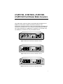
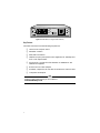
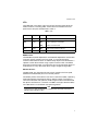
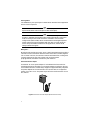
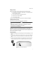
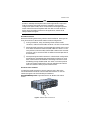
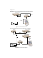
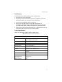
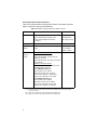
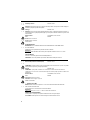
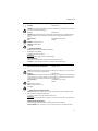
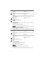
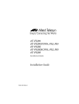
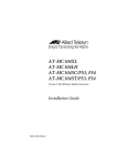
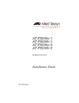
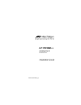
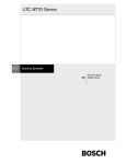
AT-MC101XL AT-MC102XL AT-MC103XL AT-MC103LH Fast Ethernet Media Converters Installation Guide PN 613-10771-00 Rev. C Copyright 1998, 1999 Allied Telesyn International, Corp. 960 Stewart Drive Suite B, Sunnyvale CA USA 94086 All rights reserved. No part of this publication may be reproduced without prior written permission from Allied Telesyn International, Corp. Ethernet is a registered trademark of Xerox Corporation. All other product names, company names, logos or other designations mentioned herein are trademarks or registered trademarks of their respective owners. Allied Telesyn International, Corp. reserves the right to make changes in specifications and other information contained in this document without prior written notice. The information provided herein is subject to change without notice. In no event shall Allied Telesyn International, Corp. be liable for any incidental, special, indirect, or consequential damages whatsoever, including but not limited to lost profits, arising out of or related to this manual or the information contained herein, even if Allied Telesyn International, Corp. has been advised of, known, or should have known, the possibility of such damages. Safety Warnings STANDARDS: This product meets the following standards U.S. Federal Communications Commission RADIATED ENERGY Note: This equipment has been tested and found to comply with the limits for a Class A digital device pursuant to Part 15 of FCC Rules. These limits are designed to provide reasonable protection against harmful interference when the equipment is operated in a commercial environment. This equipment generates, uses, and can radiate radio frequency energy and, if not installed and used in accordance with this instruction manual, may cause harmful interference to radio communications. Operation of this equipment in a residential area is likely to cause harmful interference in which case the user will be required to correct the interference at his own expense. Note: Modifications or changes not expressly approved of by the manufacturer or the FCC, can void your right to operate this equipment. Industry Canad This Class A digital apparatus meets all requirements of the Canadian Interference-Causing Equipment Regulations. Cet appareil numérique de la classe A respecte toutes les exigences du Règlement sur le matériel brouilleur du Canada. RFI Emission EN55022 Class A ! 1 WARNING: In a domestic environment this product may cause radio interference in which case the user may be required to take adequate measures. ! 2 Immunity EN50082-1 1997 WARNING: This product requires shielded cables to comply with emission and immunity standards. If it is used with unshielded cables, the user may be required to take measures to correct the interference problem at their own expense. Electrical Safety TUV-EN60950, UL1950, CSA 950 Laser EN60825 IMPORTANT: Appendix A contains translated safety statements for installing this equipment. When you see the !, go to Appendix A for the translated safety statement in your language. WICHTIG: Anhang A enthält übersetzte Sicherheitshinweise für die Installation dieses Geräts. Wenn Sie ! sehen, schlagen Sie in Anhang A den übersetzten Sicherheitshinweis in Ihrer Sprache nach. VIGTIGT: Tillæg A indeholder oversatte sikkerhedsadvarsler, der vedrører installation af dette udstyr. Når De ser symbolet !, skal De slå op i tillæg A og finde de oversatte sikkerhedsadvarsler i Deres eget sprog. BELANGRIJK: Appendix A bevat vertaalde veiligheidsopmerkingen voor het installeren van deze apparatuur. Wanneer u de ! ziet, raadpleeg Appendix A voor vertaalde veiligheidsinstructies in uw taal. IMPORTANT: L'annexe A contient les instructions de sécurité relatives à l'installation de cet équipement. Lorsque vous voyez le symbole !, reportez-vous à l'annexe A pour consulter la traduction de ces instructions dans votre langue. TÄRKEÄÄ: Liite A sisältää tämän laitteen asentamiseen liittyvät käännetyt turvaohjeet. Kun näet !-symbolin, katso käännettyä turvaohjetta liitteestä A. IMPORTANTE: l’Appendice A contiene avvisi di sicurezza tradotti per l’installazione di questa apparecchiatura. Il simbolo !, indica di consultare l’Appendice A per l’avviso di sicurezza nella propria lingua. VIKTIG: Tillegg A inneholder oversatt sikkerhetsinformasjon for installering av dette utstyret. Når du ser !, åpner du til Tillegg A for å finne den oversatte sikkerhetsinformasjonen på ønsket språk. IMPORTANTE: O Anexo A contém advertências de segurança traduzidas para instalar este equipamento. Quando vir o símbolo !, leia a advertência de segurança traduzida no seu idioma no Anexo A. IMPORTANTE: El Apéndice A contiene mensajes de seguridad traducidos para la instalación de este equipo. Cuando vea el símbolo !, vaya al Apéndice A para ver el mensaje de seguridad traducido a su idioma. OBS! Bilaga A innehåller översatta säkerhetsmeddelanden avseende installationen av denna utrustning. När du ser !, skall du gå till Bilaga A för att läsa det översatta säkerhetsmeddelandet på ditt språk. iii AT-MC101XL, AT-MC102XL, AT-MC103XL AT-MC103LH Fast Ethernet Media Converters The AT-MC101XL and AT-MC102XL convert IEEE 802.3u 100Base-TX to 100Base-FX multimode Fast Ethernet network connections. The AT-MC103XL and AT-MC103LH convert to FX single mode. The 100Base-FX interfaces are available in ST or SC connectors for multimode fiber cabling. For single mode cabling, the 100Base-FX is available in SC connectors only. The 100Base-TX interface uses an RJ45 shielded connector. TX RX NML 100Base-FX 100Base-TX REC REC PWR LNK LNK TST NML MDI MDI-X LNK MC101XL FAST ETHERNET MEDIA CONVERTER Figure 1 AT-MC101XL Front Panel (ST multimode connector) TX RX NML 100Base-FX 100Base-TX REC REC PWR LNK LNK TST NML MDI MDI-X LNK MC102XL FAST ETHERNET MEDIA CONVERTER Figure 2 AT-MC102XL Front Panel (SC multimode connector) CLASS 1 LASER LIGHT DO NOT STARE INTO BEAM TX RX 100Base-FX 100Base-TX NML REC REC PWR LNK LNK TST NML MDI MDI-X LNK MC103XL SINGLE MODE FIBER FAST ETHERNET MEDIA CONVERTER Figure 3 AT-MC103XL Front Panel (SC single mode connector) 1 CLASS 1 LASER LIGHT DO NOT STARE INTO BEAM TX RX 100Base-FX 100Base-TX NML REC REC PWR LNK LNK TST NML MDI MDI-X LNK MC103LH SINGLE MODE FIBER LONG HAUL FAST ETHERNET MEDIA CONVERTER Figure 4 AT-MC103LH (SC single mode connector) Key Features The media converters have the following key features: ❑ LEDs for unit and port status ❑ MDI/MDI-X Switch ❑ NML/LNK TST Switch ❑ 100Base-TX ports participate in auto-negotiation for 100 Mbps and half- or full-duplex modes ❑ MissingLink provides link fault detection on 100Base-TX and 100Base-FX segments ❑ External AC-DC Power Adapter ❑ Standard, compact size for use with AT-MCR12 rack-mount chassis ❑ Low power consumption Note For definitions of technical terms associated with Allied Telesyn’s products, refer to the Glossary on our website at www.alliedtelesyn.com. 2 Installation Guide LEDs The PWR LED in the upper right corner of the front panel lights when the media converter is receiving power. Status LEDs are located on the front panel next to each port and described in Table 1. Table 1 LEDs LED Color State Description PWR Green ON Power is applied. NML Green ON Unit is operating in normal mode. OFF Unit is in Link Test mode. REC Green ON Data is being received on the port. LNK Green ON Link established on the port. MDI/MDI-X Switch The MDI/MDI-X (Media Dependent Interface/Media Dependent Interface with Crossover) switch, located on the front panel, is a straight-through or crossover cable selection switch. It enables the RJ45 port to be connected to a repeater or DTE device without using a special crossover cable. The default position of the switch is MDI-X, which means you can connect the RJ45 port to a workstation or to any other DTE device using a straight-through cable. NML/LNK TST Switch The NML/LNK TST (Normal/Link Test) switch, located on the front panel, establishes a fiber/twisted pair link in the test position. The default position of the switch is IN, which is the normal (NML) operating mode and enables the MissingLink feature. With the switch in the OUT or Link Test mode (LNK TST) position, the MissingLink feature is disabled and the optical transmitter TX is forced on. The NML LED lights when the NML/ TST LNK switch is in the default (IN) operating position. Note Using the Link Test mode does not interfere with the media converter’s ability to pass network traffic. 3 Auto-Negotiation The 100Base-TX ports participate in IEEE 802.3u Standard auto-negotiation with its local link partner. Note End stations used with the media converter must operate in the same duplex mode (either both full-duplex or both half-duplex). Note The media converters have an additional feature, allowing the unit to operate in 100 Mbps half-duplex mode. Certain applications require this mode, for example, two media converters installed in a back-to-back configuration (fiber-to-fiber) which are attached to unmanaged repeaters and/or switches that auto-negotiates with the other. Forinstructions on how to set up the media converter for this application, contact Allied Telesyn Technical Support. MissingLink MissingLink gives the host (router, server, switch) attached to each end of the converter critical information about the status of the other (remote) segment link. If either link fails, the converter interacts with both hosts, making each instantly aware of the link fault. Either host can then execute preprogrammed, redundant transmission path selection. External AC-DC Power Adapter An external AC-to-DC power adapter is included with the fast switch for standalone operation (see Figure 5). The power adapter supplies 12 volts DC to the media converter. Allied Telesyn supplies an approved safety compliant AC power adapter for the 120 and 240 V AC versions with an unregulated output of 12 V DC at 1 A. The power required for the media converter is 12 V DC, 500 mA. Figure 5 External AC-DC Power Adapter (North American version) 4 Installation Guide Package Contents Make sure the media converter package contains the following items: ❑ AT-MC101XL, AT-MC102XL, AT-MC103XL, or AT-MC103LH Fast Ethernet Media Converter ❑ Four Protective Feet (for standalone use only) ❑ External AC-DC Power Adapter ❑ This Installation Guide Contact your sales representative if any items are missing or damaged. Installing the Media Converter Read the warnings below before beginning any installation. Warning Do not stare into the laser beam when installing the media converters. !5 LIGHTNING DANGER: DO NOT WORK on equipment or CABLES during periods of LIGHTNING ACTIVITY! 6 DO NOT BLOCK AIR VENTS ! 7 The following steps are for a standalone installation. To install media converters in a rack mount chassis, see “Rack mount Chassis Installation” on page 7. For information concerning back-to-back converter configuration, see “Back-to-Back Installation” on page 7. Standalone Installation 1. Remove all equipment from the package and store the packaging in a safe place 2. Attach the four rubber feet to the base of the unit, placing one rubber foot in each corner. For rack-mount installation, do not attach the four rubber feet. 3. Plug the AC-DC power adapter into an appropriate AC power outlet and insert the power plug into the DC receptacle located on the rear panel. 12 V D C Figure 6 12 V DC Connector on Rear Panel 5 4. Verify that the PWR LED lights green. 5. Set the unit in Link Test mode 6. Remove the dust cap from the fiber optic connectors. 7. Plug the appropriate fiber cable into the connector. See Table 3 for IEEE 802.3u cabling specifications 8. Connect the other end of the fiber cable to the desired end station. Verify that the link LED is ON. 9. If you are making a direct connection to a workstation using straightthrough cable, set the MDI/MDI-X switch to the MDI-X position. (MDI-X is the default position.) If you are connecting the media converter to a hub, switch, or another media converter with a straight-through cable, set the MDI/MDI-X switch to the MDI position. See Figure 7. TX NML LNK TST RX 100Base-FX 100Base-TX REC REC PWR LNK NML MDI MDI-X LNK MC101XL FAST ETHERNET MEDIA CONVERTER C K MDI MDI-X Figure 7 MDI/MDI-X Switch 10. Plug a Category 5 twisted pair cable into the RJ45 connector. Connect the other end of the twisted pair cable to the desired end station. Verify that the Link LED is ON 11. Set the unit to Normal (NML) Mode for normal operation. Note End stations used with the media converter must operate in the same duplex mode (either both full-duplex or both half-duplex). 6 Installation Guide Note The media converters have an additional feature, allowing the unit to operate in 100 Mbps half-duplex mode. Certain applications require this mode, for example, two media converters installed in a back-to-back configuration (fiber-to-fiber) which are attached to unmanaged repeaters and/or switches that auto-negotiates with the other. Forinstructions on how to set up the media converter for this application, contact Allied Telesyn Technical Support. Back-to-Back Installation Review the following before doing a back-to-back installation. See Figure 10 for an illustration of a back-to-back-media converter configuration. ❑ During installation, setup, and testing of back-to-back media converters, make sure each media converter is in the Link Test mode. ❑ When two media converters are connected back-to-back with no UTP/ STP cables connected and when the NML/LNK TST switch is in the OUT position (Link Test mode), the fiber REC LEDs on each converter may flash. This is normal and will not affect the normal operation of the converters. ❑ When operating two media converters in a back-to-back configuration, Allied Telesyn recommends that the MissingLink feature on one or both of the converters be disabled. The MissingLink feature can be disabled by placing the NML/LNK TST switch in the OUT position (LNK TST mode). Disabling the Link Test mode does not interfere with the converter’s ability to pass network traffic. Rack mount Chassis Installation LNK 100Base-TX LNK REC REC MC102 FAST ETHERNET MEDIA CONVERTER MDI 100Base-TX LNK MDI-X REC 100Base-FX RX TX PWR LNK 100Base-TX REC MDI-X MDI LNK REC 100Base-FX RX TX LNK MC102 FAST ETHERNET MEDIA CONVERTER PWR REC MDI-X MDI MC102 FAST ETHERNET MEDIA CONVERTER LNK 100Base-TX REC 100Base-FX RX TX LNK MC102 FAST ETHERNET MEDIA CONVERTER PWR REC MDI 100Base-TX LNK MDI-X REC LNK 100Base-FX RX TX PWR REC MDI-X MDI MC102 FAST ETHERNET MEDIA CONVERTER LNK 100Base-TX REC 100Base-FX RX TX LNK MC102 FAST ETHERNET MEDIA CONVERTER PWR REC MDI 100Base-TX LNK MDI-X REC LNK 100Base-FX RX TX PWR REC MDI-X MDI MC102 FAST ETHERNET MEDIA CONVERTER LNK 100Base-TX REC 100Base-FX RX TX MC102 FAST ETHERNET MEDIA CONVERTER PWR LNK 100Base-TX REC MDI MDI-X LNK PWR LNK REC 100Base-FX RX TX MDI-X MDI MC102 FAST ETHERNET MEDIA CONVERTER REC 100Base-TX LNK 100Base-FX RX MC102 FAST ETHERNET MEDIA CONVERTER TX PWR REC LNK MDI-X MDI REC LNK LNK MDI-X MDI 100Base-FX LNK REC 100Base-FX MDI-X RX MDI LNK REC TX RX TX MC102 FAST ETHERNET MEDIA CONVERTER 100Base-FX 100Base-TX RX PWR TX PWR PWR REC MC102 FAST ETHERNET MEDIA CONVERTER 100Base-TX MCR12 REC To install the media converter in the rack-mount chassis, refer to the “AT-MCR12 Media Converter Chassis Installation Manual” or visit the Technical Support area of Allied Telesyn’s website at www.alliedtelesyn.com. Figure 8 shows the AT-MCR12 rack-mount chassis. Figure 8 AT-MCR12 Rack-mount Chassis 7 Configurations Figure 9 shows a typical network configuration with a workstation connected to a switch. AT-8124XL 10/100 Switch PORT ACTIVITY RS-232 TERMINAL PORT AT-MC101XL STATUS 10BASE-T / 100BASE-TX 10BASE-T / 100BASE-TX SWITCH FAST ETHERNET 100Base-TX 100Base-FX MMF Legend 10 Mbps 100 Mbps 100 Mbps (Fiber) Workstation Figure 9 Connection to Workstation and Switch Figure 10 shows two media converters in a back-to-back configuration. AT-8124XL 10/100 Switch AT-MC101XL PORT ACTIVITY RS-232 TERMINAL PORT STATUS 10BASE-T / 100BASE-TX 10BASE-T / 100BASE-TX SWITCH FAST ETHERNET 100Base-TX AT-8124XL 10/100 Switch 100Base-FX PORT ACTIVITY RS-232 TERMINAL PORT STATUS 10BASE-T / 100BASE-TX 10BASE-T / 100BASE-TX SWITCH FAST ETHERNET MMF 100Base-TX 10Base-T AT-MC101XL Legend 10 Mbps 100 Mbps 100 Mbps (Fiber) Workstation Figure 10 AT-MC101XL Back-to-Back Configuration 8 Installation Guide Troubleshooting To troubleshoot your media converter, perform the following: 1. Set the unit in the Link Test mode. 2. End stations used with the media converter must operate in the same duplex mode (either both full-duplex or both half-duplex). 3. Verify that the twisted pair cable is Category 5. 4. Verify that proper fiber cable is being used: multimode for the AT-MC101XL and AT-MC102XL, and single mode for the AT-MC103XL and AT-MC103LH. Refer to Table 3 on page 10 for cable specifications 5. Verify that the near end node transmitter (TX) is connected to the far end node receiver (RX) and vice versa on the fiber segment. Technical Specifications Table 2 lists the media converter technical specifications. Table 2 Media Converter Technical Specifications Specifications Dimensions 4.125 in W x 3.75 in D x 1.0 in H (10.5 cm W x 9.5 cm D x 2.5 cm H) Max. Operating temperature 0° C to 40° C (32° F to 104° F) Max. Storage temperature -20 oC to 80o C (-4° F to 176° F) Operating altitude up to 10,000 ft (3,048 m) Humidity 5% to 80% (noncondensing) EMI/RFI meets FCC Class A, EN55022 Class A Safety EN60950, UL 1950, CSA 950 EN60825 Immunity EN50082-1 Immunity Standard Power Input supply voltage Max. current Power consumption 12 V DC +/-5% 500 mA 6W 9 Recommended Cables and Cable Specifications Table 3 lists the IEEE 802.3u cabling specifications for the media converters. Refer to Table 3 for cabling recommendations. Table 3 IEEE 802.3u Cabling Specifications for Media Converters 100Base-FX 100Base-TX Media 1300 nm multimode fiber, 50/125 micron 1300 nm multimode fiber, 62.5/125 micron 1300 nm single-mode fiber, 9/125 micron (see Note 1) Unshielded/ ShieldedTwisted Pair Category 5 only Topology Star, Tree Star, Tree External Devices Network Adapter Card, Repeater, Switch, Router, or Bridge Network Adapter Card, Repeater, Switch, or Router Maximum Segment Length 100BaseFX Full-Duplex operation: Multimode fiber (MMF), 2 km (1.2 mi) Single mode fiber (SMF), 15 km (9.32 mi) (XL model only, see Note 3.) Single mode fiber (SMF), 40km (24.9 mi) (LH model only, see Note 4.) 100BaseFX Half-Duplex operation: The total distance of all fiber runs cannot exceed the following limits: (see Note 2) with one Media Converter inline: Switch to Switch = 372 m (1221 ft) Work Station to Switch = 372 m (1221 ft) Switch to Class II Repeater = 185 m (607 ft) Switch to Class I Repeater = 137 m (450 ft) with two Media Converters inline: Switch to Switch = 332 m (1089 ft) Work Station to Switch = 332 m (1089 ft) Switch to Class II Repeater =145 m (476 ft) Switch to Class I Repeater = 97 m (318 ft) 328 ft (100 m) Note 1. Single-mode fiber transmitter is rated as a Class 1 laser. Note 2. Each Media Converter used inline within a single collision domain will reduce the overall segment length by 40 m (131.24 ft) of fiber. Note 3. Applies only to the AT-MC103XL, Single Mode Fiber OpticTransmitter/Receiver. Note 4. Applies only to the AT-MC103LH, Single Mode Fiber Optic Transmitter/Receiver. 10 Installation Guide Technical Support and Service You can contact the reseller or distributor where you purchased your product for local assistance. If local support is unable to resolve the problem, Allied Telesyn offers technical support via fax, e-mail or telephone. Refer to Appendi xD, for technical support telephone and fax numbers or www.alliedtelesyn.com for current world-wide office locations. Warranty The media converters have a lifetime warranty. The power adapter has a one year warranty. 11 Appendix A Electrical Safety and Installation Requirements STANDARDS: This product meets the following standards U.S. Federal Communications Commission RADIATED ENERGY Note: This equipment has been tested and found to comply with the limits for a Class A digital device pursuant to Part 15 of FCC Rules. These limits are designed to provide reasonable protection against harmful interference when the equipment is operated in a commercial environment. This equipment generates, uses, and can radiate radio frequency energy and, if not installed and used in accordance with this instruction manual, may cause harmful interference to radio communications. Operation of this equipment in a residential area is likely to cause harmful interference in which case the user will be required to correct the interference at his own expense. Note: Modifications or changes not expressly approved of by the manufacturer or the FCC, can void your right to operate this equipment. Industry Canada This Class A digital apparatus meets all requirements of the Canadian Interference-Causing Equipment Regulations. Cet appareil numérique de la classe A respecte toutes les exigences du Règlement sur le matériel brouilleur du Canada. STANDARDS: This product meets the following standards !1 !2 RFI Emission EN55022 Class A WARNING: In a domestic environment this product may cause radio interference in which case the user may be required to take adequate measures. !3 !4 Immunity EN50082-1 1997 WARNING: This product requires shielded cables to comply with emission and immunity standards. If it is used with unshielded cables, the user may be required to take measures to correct the interference problem at their own expense. Electrical Safety TUV-EN60950, UL1950, CSA 950 Laser EN60825 Warning Class 1 Laser product. !5 Warning Do not stare into the Laser beam. At time of installation, the Fiber Optic Lasers comply with FDA Radiation Performance Standard 21CFR Subchapter J, applicable at date of manufacture. Use of controls or adjustments of performance or procedures other than those specified herein may result in hazardous radiation exposure. SAFETY !6 LIGHTNING DANGER DANGER: DO NOT WORK on equipment or CABLES during periods of LIGHTNING ACTIVITY. !7 DO NOT BLOCK AIR VENTS Power to the hub must be sourced only from the adapter. USA/CANADA Use a UL Listed/CSA Certified AC adapter of DC 12V, 500mA. EUROPE - EU Use TÜV licensed AC adapter of DC 12V, 500mA. UK Use a UK Safety Approved AC adapter of DC 12V, minimum 500mA. 13 OPERATING TEMPERATURE This product is designed for a maximum ambient temperature of 40 degrees C. ALL COUNTRIES: Install product in accordance with local and National Electrical Codes. NORMEN: Dieses Produkt erfüllt die Anforderungen der nachfolgenden Normen !1 !2 Hochfrequenzstörung EN55022 Klasse A WARNUNG: Bei Verwendung zu Hause kann dieses Produkt Funkstörungen hervorrufen. In diesem Fall müßte der Anwender angemessene Gegenmaßnahmen ergreifen. !3 !4 Störsicherheit EN50082-1 1997 ACHTUNG: Für dieses Produkt sind abgeschirmte Kabel erforderlich, damit den Richtlinien für Emission und Interferenzschutz entsprochen wird. Falls das Produkt mit nicht abgeschirmten Kabeln verwendet wird, können weitergehende Maßnahmen für die Korrektur von Interferenzproblemen auf Kosten des Benutzers notwendig werden. Elektrische Sicherheit TUV-EN60950, UL1950, CSA 950 Laser EN60825 Warnung Laserprodukt der Klasse 1. !5 Warnung Nicht direkt in den Strahl blicken. SICHERHEIT !6 GEFAHR DURCH BLITZSCHLAG GEFAHR: Keine Arbeiten am Gerät oder an den Kabeln während eines Gewitters ausführen !7 ENTLÜFTUNGSÖFFNUNGEN NICHT VERSPERREN Der Buchse darf nur aus dem Adapter Strom zugeführt werden. EUROPE - EU Gebrauchen Sie einen von TÜV zugelassenen Wechselstromadapter für Gleichstrom 12 V, 500 mA. BETRIEBSTEMPERATUR Dieses Produkt wurde für den Betrieb in einer Umgebungstemperatur von nicht mehr als 40° C entworfen. ALLE LÄNDER: Installation muß örtlichen und nationalen elektrischen Vorschriften entsprechen. STANDARDER: Dette produkt tilfredsstiller de følgende standarder !1 !2 Radiofrekvens forstyrrelsesemission EN55022 Klasse A ADVARSEL: I et hjemligt miljø kunne dette produkt forårsage radio forstyrrelse. Bliver det tilfældet, påkræves brugeren muligvis at tage tilstrækkelige foranstaltninger. !3 !4 Immunitet EN50082-1 1997 ADVARSEL: Dette produkt skal bruges med afskærmede kabler for at overholde bestemmelserne vedrørende udstråling og støjimmunitet. Hvis det bruges med uafskærmede kabler, kan det blive påkrævet af brugeren at korrigere interferensproblemer for egen regning. Elektrisk sikkerhed. TUV-EN60950, UL1950, CSA 950 Laser EN60825 Advarsel Laserprodukt av klasse 1. !5 Advarsel Stirr ikke på strålen. SIKKERHED !6 FARE UNDER UVEJR FARE: UNDLAD at arbejde på udstyr eller KABLER i perioder med LYNAKTIVITET. !7 VENTILATIONSÅBNINGERNE MÅ IKKE BLOKERES Strømforsyningen til apparatet må udelukkende tages fra tilpasningstransformatoren. EUROPE - EU Brug kun TÜV godkendt vekselstrømstransformator på 12 V jævnstrøm, 500 mA. BETJENINGSTEMPERATUR Dette apparat er konstrueret til en omgivende temperatur på maksimum 40 grader C. 14 Installation Guide ALLE LANDE: Installation af produktet skal ske i overensstemmelse med lokal og national lovgivning for elektriske installationer. EISEN: Dit product voldoet aan de volgende eisen. !1 !2 RFI Emissie EN55022 Klasse A WAARSCHUWING: Binnenshuis kan dit product radiostoring veroorzaken, in welk geval de gebruiker verplicht kan worden om gepaste maatregelen te nemen. !3 !4 Immuniteit EN50082-1 1997 WAARSCHUWING: Om te voldoen aan de emissie- en immuniteitsnormen dient dit apparaat te zijn voorzien van afgeschermde kabels. Als het met niet-afgeschermde kabels wordt gebruikt, kan het zijn dat de gebruiker maatregelen moet treffen om interferentieproblemen voor eigen rekening op te lossen. Electrische Veiligheid TUV-EN60950, UL1950, CSA 950 Laser EN60825 Waarshuwing Klasse-1 laser produkt. !5 Waarchuwing Neit in de straal staren. VEILIGHEID ! 6GEVAAR VOOR BLIKSEMINSLAG GEVAAR: NIET aan toestellen of KABELS WERKEN bij BLIKSEM. !7 VENTILATIEGATEN NIET BLOKKEREN Stroom mag alleen via de adapter naar het apparaat toegevoerd worden. EUROPE - EU Gebruik een door TÜV gekeurde wisselstroomadapter van 12 Volt gelijkstroom, 500 milliampères. BEDRIJFSTEMPERATUUR De omgevingstemperatuur voor dit produkt mag niet meer bedragen dan 40 graden Celsius. ALLE LANDEN: het toestel installeren overeenkomstig de lokale en nationale elektrische voorschriften. NORMES: ce produit est conforme aux normes de suivantes !1 !2 Emission d'interférences radioélectriques EN55022 Classe A MISE EN GARDE: dans un environnement domestique, ce produit peut provoquer des interférences radioélectriques. Auquel cas, l'utilisateur devra prendre les mesures adéquates. !3 !4 Immunité EN50082 - 1 1997 AVERTISSEMENT: Il faut utiliser des câbles blindés pour ce produit afin de respecter les normes d’émission et d’immunité. Si l’utilisateur choisit d’utiliser des câbles non blindés, il sera peut-être contraint de prendre les mesures nécessaires pour corriger les problèmes d’interférences, ainsi que d’assumer le coût correspondant. Sécurité électrique TUV-EN60950, UL1950, CSA 950 Laser EN60825 Attention Producit laser di classe 1. !5 Attention Ne pas fixer le faisceau des yeux. SÉCURITÉ !6 DANGER DE FOUDRE DANGER: NE PAS MANIER le matériel ou les CÂBLES lors d'activité orageuse. !7 NE PAS BLOQUER LES FENTES D'AÉRATION L'alimentation du concentrateur doit être uniquement fournie par l'adaptateur. EUROPE - EU Utiliser un adaptateur secteur conforme TÜV de 12 V, 500 mA en courant continu. TEMPÉRATURE DE FONCTIONNEMENT Ce matériel est capable de tolérer une température ambiante maximum de 40 degrés Celsius. POUR TOUS PAYS: Installer le matériel conformément aux normes électriques nationales et locales. 15 STANDARDI : Tämä tuote on seuraavien standardien mukainen !1 !2 Radioaaltojen häirintä EN55022 Luokka A VAROITUS: Kotiolosuhteissa tämä laite voi aiheuttaa radioaaltojen häiröitä, missä tapauksessa laitteen käyttäjän on mahdollisesti ryhdyttävä tarpeellisiin toimenpiteisiin. !3 !4 Kestävyys EN50082-1 1997 VAROITUS: Tämä tuote vaatii suojattuja kaapeleita toimiakseen emissio- ja häiriönsietostandardien mukaisesti. Jos tuotetta käytetään ilman suojattuja kaapeleita, käyttäjä voi joutua korjaamaan häirinnän aiheuttaman ongelman omalla kustannuksellaan. Sähköturvallisuus TUV-EN60950, UL1950, CSA 950 Laser EN60825 Varoitus Luokan 1 Lasertuote. !5 Variotus Älä katso säteeseen. TURVALLISUUS !6 SALAMANISKUVAARA ENGENVAARA: ÄLÄ TYÖSKENTELE laitteiden tai KAAPELEIDEN KANSSA SALAMOINNIN AIKANA. !7 ÄLÄ TUKI ILMAREIKIÄ Tähtipisteeseen (hub) syötettävän virran pitää tulla ainoastaan sovittimesta. EUROPE - EU Käytä TÜV-lisenssillä valmistettua verkkosovitinta, jonka tasajännitteen nimellisarvot ovat DC 12 V, 500 mA (milliampeeria). KÄYTTÖLÄMPÖTILA Tämä tuote on suunniteltu ympäröivän ilman maksimilämpötilalle 40° C. KAIKKI MAAT: Asenna tuote paikallisten ja kansallisten sähköturvallisuusmääräysten mukaisesti. STANDARD: Questo prodotto è conforme ai seguenti standard !1 !2 Emissione RFI (interferenza di radiofrequenza) EN55022 Classe A AVVERTENZA: in ambiente domestico questo prodotto potrebbe causare radio interferenza. In questo caso potrebbe richiedersi all'utente di prendere gli adeguati provvedimenti. !3 !4 Immunità EN50082-1 1997 AVVERTENZA: questo prodotto, se utilizzato con cavi schermati, è conforme alle norme sulle emissioni e sull’immunità. In caso di uso senza cavi schermati, l’utente può dover adottare a proprie spese misure correttive contro le interferenze. Sicurezza elettrica TUV-EN60950, UL1950, CSA 950 Laser EN60825 Avvertenza Prodotto laser di Classe 1. !5 Avertenza Non fissare il raggio con gli occhi. NORME DI SICUREZZA ! 6PERICOLO DI FULMINI PERICOLO: NON LAVORARE sul dispositivo o sui CAVI durante PRECIPITAZIONI TEMPORALESCHE. !7 NON OSTRUIRE LE PRESE D'ARIA Questo dispositivo deve essere alimentato solo mediante l’adattatore. EUROPE - EU Utilizzare l’adattatore per c.a. da 12 V c.c. e 500 mA conforme alla normativa TÜV. TEMPERATURA DI FUNZIONAMENTO Questo prodotto è concepito per una temperatura ambientale massima di 40 gradi centigradi. TUTTI I PAESI: installare il prodotto in conformità delle vigenti normative elettriche nazionali. 16 Installation Guide SIKKERHETSNORME : Dette produktet tilfredsstiller følgende sikkerhetsnormer !1 !2 RFI stråling EN55022 Klasse A ADVARSEL: Hvis dette produktet benyttes til privat bruk, kan produktet forårsake radioforstyrrelse. Hvis dette skjer, må brukeren ta de nødvendige forholdsregler. !3 !4 Immunitet EN50082-1 1997 ADVARSEL: Dette produktet må brukes med vernede kabler for å tilfredsstille emisjons- og fritakelsesstandarder. Dersom produktet brukes med uvernede kabler, må brukeren muligens rette forstyrrelsesproblemene for egen regning. Elektrisk sikkerhet TUV-EN60950, UL1950, CSA 950 Laser EN60825 ADVARSEL Laserprodukt av klasse 1. !5 ADVARSAL Stirr ikke på strålen. SIKKERHET ! 6FARE FOR LYNNEDSLAG FARE: ARBEID IKKE på utstyr eller KABLER i TORDENVÆR. !7 BLOKKER IKKE LUFTVENTILENE All strømtilførsel må komme fra adapteren. EUROPE - EU Benytt TÜV-godkjent AC-adapter på 12V DC, 500mA (millismpere) DRIFTSTEMPERATUR Dette produktet er konstruert for bruk i maksimum romtemperatur på 40 grader celsius. ALLE LAND: Produktet må installeres i samsvar med de lokale og nasjonale elektriske koder. PADRÕES: Este produto atende aos seguintes padrões. !1 !2 Emissão De Interferência De Radiofrequência EN55022 Classe A AVISO: Num ambiente doméstico este produto pode causar interferência na radiorrecepção e, neste caso, pode ser necessário que o utente tome as medidas adequadas. !3 !4 Imunidade EN50082-1 1997 ADVERTÊNCIA: Este produto requer a utilização de cabos blindados para cumprimento dos standards de limites de emissão e imunidade. Se o produto for utilizado com cabos não blindados, o utilizador poderá necessitar de tomar medidas para correcção de problemas de interferência, por sua própria conta. Segurança Eléctrica TUV-EN60950, UL1950, CSA 950 Laser EN60825 Aviso Produto laser de classe 1. !5 Aviso Não olhe fixamente para o raio. SEGURANÇA ! 6PERIGO DE CHOQUE CAUSADO POR RAIO PERIGO: NÃO TRABALHE no equipamento ou nos CABOS durante períodos suscetíveis a QUEDAS DE RAIO. !7 NÃO BLOQUEIE AS ABERTURAS DE VENTILAÇÃO Use somente o adaptador fornecido para alimentação elétrica do hub. EUROPE - EU Use um adaptador de corrente alternada com saída DC de 12V e 500mA em conformidade com as especificações da TÜV. TEMPERATURA DE FUNCIONAMENTO Este produto foi projetado para uma temperatura ambiente máxima de 40 graus centígrados. TODOS OS PAÍSES: Instale o produto de acordo com as normas nacionais e locais para instalações elétricas. 17 ESTÁNDARES: Este producto cumple con los siguientes estándares !1 !2 Emisión RFI EN55022 Clase A ADVERTENCIA: en un entorno doméstico, este producto puede causar radiointerferencias, en cuyo caso, puede requerirse del usuario que tome las medidas que sean convenientes al respecto. !3 !4 Inmunidad EN50082-1 1997 ADVERTENCIA: Este producto exige cables protectores para ajustarse a las normas de emisión e inmunidad. Si se utiliza con cables sin protección, el usuario tendrá que correr con los gastos por las medidas a tomar en caso de problemas de interferencias. Seguridad eléctrica TUV-EN60950, UL1950, CSA 950 Laser EN60825 ¡ADVERTENCIA! Producto láser Clase 1. !5 ¡ADVERTENCIA! No mirat fijamente el haz. SEGURIDAD ! 6PELIGRO DE RAYOS ELIGRO: NO REALICE NINGUN TIPO DE TRABAJO O CONEXION en los equipos o en LOS CABLES durante TORMENTAS ELECTRICAS. !7 NO BLOQUEE LAS ABERTURAS PARA VENTILACION La energía para el dispositivo central o "hub" debe provenir únicamente del adaptador. EUROPE - EU Utilizar un adaptador de corriente alterna autorizado TÜV de 12 voltios de corriente continua y 500 miliamperios. TEMPERATURA REQUERIDA PARA LA OPERACIÓN Este producto está diseñado para una temperatura ambiental máxima de 40 grados C. PARA TODOS LOS PAÍSES: Monte el producto de acuerdo con los Códigos Eléctricos locales y nacionales. STANDARDER: Denna produkt uppfyller följande standarder !1 !2 Radiostörning EN55022 Klass A VARNING: Denna produkt kan ge upphov till radiostörningar i hemmet, vilket kan tvinga användaren till att vidtaga erforderliga åtgärder. !3 !4 Immunitet EN50082-1 1997 VARNING! Denna produkt kräver skärmade kablar för att uppfylla standardkraven för emission och immunitet. Om den används med oskärmade kablar kan användaren vara tvungen att vidta åtgärder på egen bekostnad för att åtgärda störningsproblemet. Elsäkerhet TUV-EN60950, UL1950, CSA 950 Laser EN60825 VARNING! Laserprodukt av klass 1. !5 VARNING! Laserstrålning när enheten är öppen. SÄKERHET ! 6FARA FÖR BLIXTNEDSLAG FARA: ARBETA EJ på utrustningen eller kablarna vid ÅSKVÄDER. !7 BLOCKERA INTE LUFTVENTILERNA Endast anslutningsenheten får vara kraftkälla till centralen. EUROPE - EU Använd en växelströmsanslutningsenhet licensierad av TÜV. Likström 12V, 500mA. DRIFTSTEMPERATUR Denna produkt är konstruerad för rumstemperatur ej överstigande 40 grader Celsius. ALLA LÄNDER: Installera produkten i enlighet med lokala och statliga bestämmelser för elektrisk utrustning. 18 Appendix B AT-MC101XL, AT-MC102XL, AT-MC103XL, and AT-MC103LH Installation Guide Feedback Please tell us what additional information you would like to see discussed in this guide. If there are topics you would like information on that were not covered in this guide, please photocopy this page, answer the questions and fax or mail this form back to Allied Telesyn. The mailing address and fax number are at the bottom of the page. Your comments are valuable when we plan future revisions of this guide. I found the following the most valuable __________________________________ ______________________________________________________________________ ______________________________________________________________________ ______________________________________________________________________ ______________________________________________________________________ I would like the following more developed ________________________________ ______________________________________________________________________ ______________________________________________________________________ ______________________________________________________________________ ______________________________________________________________________ I would find this guide more useful if ____________________________________ ______________________________________________________________________ ______________________________________________________________________ ______________________________________________________________________ ______________________________________________________________________ Please fax or mail your feedback. Fax to 1-408-736-0100. Or mail to: Allied Telesyn International, Corp. c/o Technical Communications 960 Stewart Drive, Suite B Sunnyvale, CA 94086 USA PN 613-10771-00 Rev C 19 Appendix C Technical Support Fax Order Name _________________________________________________________________ Company ______________________________________________________________ Address _______________________________________________________________ City______________________ State/Province_______________________________ Zip/Postal Code ________________ Country_______________________________ Phone______________________________ Fax________________________________ Incident Summary Model number of Allied Telesyn product I am using _______________________ Firmware release number of Allied Telesyn product _______________________ Other network software products I am using (e.g., network managers) ______________________________________________________________________ ______________________________________________________________________ Brief summary of problem ______________________________________________ ______________________________________________________________________ Conditions (List the steps that led up to the problem.) _____________________ ______________________________________________________________________ ______________________________________________________________________ ______________________________________________________________________ ______________________________________________________________________ ______________________________________________________________________ ______________________________________________________________________ Detailed description (Please use separate sheet) Please also fax printouts of relevant files such as batch files and configuration files. When completed, fax this sheet to the appropriate Allied Telesyn office. Fax numbers can be found on page 23. 21 Appendix D Where To Find Us For Technical Support or Service Location Phone Fax Americas United States, Canada, Mexico, Central America, South America 1 (800) 428-4835 1 (918) 628-3222 Asia Singapore, Taiwan, Thailand, Malaysia, Indonesia, Korea, Philippines, China, India, Hong Kong (+65) 3815-612 (+65) 3833-830 Australia Australia, New Zealand 1 (800) 000-880 (+61) 2-9438-4966 France France, Belgium, Luxembourg, The Netherlands, Middle East, Africa (+33) 1-60-92-15-32 (+33) 1-69-28-37-49 Germany Germany, Switzerland, Austria, Eastern Europe (+49) 30-435-900-126 (+49) 30-435-70-650 Italy Italy, Spain, Portugal, Greece, Turkey, Israel (+39) 02-416047 (+39) 02-419282 Japan (+81) 3-3443-5640 (+81) 3-3443-2443 United Kingdom United Kingdom, Denmark, Norway, Sweden, Finland, Iceland (+44) 1-235-442560 (+44) 1-235-442680 Technical Support Address [email protected] CompuServe Go ALLIED FTP Server Address: gateway.centre.com [lowercase letters] Login: anonymous [lowercase letters] Password: your e-mail address [requested by the server at login] For Sales and Corporate Information Allied Telesyn International, Corp. 19800 North Creek Parkway, Suite 200 Bothell,WA 98011 Tel: 1 (425) 487-8880 Fax: 1 (425) 489-9191 Allied Telesyn International, Corp. 960 Stewart Drive, Suite B Sunnyvale, CA 94086 Tel: 1 (800) 424-4284 (USA and Canada) Fax: 1 (408) 736-0100 World Wide Web http://www.alliedtelesyn.com 23