1
MAINTENANCE
MANUAL
AND
INSTRUCTION
BOOK
for
1955
350 c.c. and 500 c.c.
MATCHLESS
SPRING FRAME AND RIGID
SINGLE CYLINDER MODELS
PRICE 2/6 NETT
MATCHLESS
MOTOR
CYCLES
PROPRIETORS : ASSOCIATED MOTOR CYCLES LIMITED
PLUMSTEAD • LONDON • S.E.18
M A I N T E N ANCE MANUAL
AND INSTRUCTION BOOK
for
1955
SINGLE CYLINDER MOTOR CYCLES
Compiled and Issued by the Manufacturers :
MATCHLESS MOTOR CYCLES
(Proprietors : ASSOCIATED MOTOR CYCLES LIMITED)
Registered Offices :
PLUMSTEAD ROAD, PLUMSTEAD
LONDON, S.E.18
..
ENGLAND
Nearest Station :
WOOLWICH ARSENAL
(Southern Region Railway)
Factories :
BURRAGE GROVE and MAXEY ROAD
PLUMSTEAD. S.E.18
Telegrams and Cables : "MATCHLESS, WOL-LONDON"
Telephone : WOOLwich 1 2 2 3 (7 Lines)
Codes : A.B.C. 5th and 6th Edition ; Bentley's ; and Private Codes
All correspondence to :
MATCHLESS MOTOR CYCLES, PLUMSTEAD ROAD, LONDON. S.E.18
Price: TWO SHILLINGS and SIXPENCE
A—S
1955 MATCHLESS MODELS
350
350
350
350
MODEL
MODEL
MODEL
MODEL
G3L RIGID FRAME (TOURING)
G3LS SPRING FRAME (TOURING)
G3LC RIGID FRAME (COMPETITION)
G3LCS SPRING FRAME (COMPETITION)
500
500
500
500
MODEL
MODEL
MODEL
MODEL
G80 RIGID FRAME (TOURING)
G80S SPRING FRAME (TOURING)
G80C RIGID FRAME (COMPETITION)
G80CS SPRING FRAME (COMPETITION)
G3L and G80 Rigid Frame
G3LS and G80S Spring Frame
INTRODUCTION
The modern motor cycle unquestionably provides one of the most healthy,
economical and pleasant means of transport. In addition by reason of its
superb braking, high power to weight ratio and ease of control it is, if used
with due care one of the safest vehicles on the road.
It is our sincere desire that every owner should obtain from his mount
the service, comfort and innumerable miles of low cost travel that we have
earnestly endeavoured to build into it.
It must be borne in mind however, that although of simple design and
construction, it is nevertheless a highly specialised piece Of engineering
and must in consequence be intelligently and efficiently maintained in
order to provide unfailing reliability.
In this book we provide non-technical instructions for carrying out all the
maintenance operations likely to be called for in normal service,' together
with assisting illustrations.
To owners of long experience we tender apologies for the elementary
nature of some of the contents of this handbook, but owners whether
novice or expert are advised to read the contents from beginning to end.
We are at all times pleased to give owners the full benefit of our wide
experience in matters relating to motor cycles of our manufacture and
elsewhere will be found details of the particulars required when making
enquiries of our Service Department.
ASSOCIATED MOTOR CYCLES
Safety on the Road
In the interest of Safety on the Road a few words of warning are perhaps not out of
place here.
The outstanding manoeuverability of a motor cycle over all other vehicles on the road
makes it necessary to exercise caution at all times.
There are unfortunately a few motor-cyclists whose reckless driving constitutes a
menace not only to themselves but also to other road users resulting in the totally false
impression in some quarters that motorcycling is a dangerous pastime.
Take a pride in your riding technique and never rely upon the other fellow doing the
right thing.
Your example of careful, courteous and unobtrusive riding will materially contribute to
road safety and to the reputation of a fine sporting pastime.
B—S.
3
DATA
Engine Number
…
…
…
frame Number
…
…
… Stamped on seat lug of main frame, on right hand side (below the saddle
Bore
…
…
…
…
…
…
…
…
…
Stroke
…
…
…
…
…
…
…
…
…
…
…
…
…
… Stamped on left hand side of crankcase
350 c.c. Models—2·7187 in. (2 F in.)
500 c.c. Models—3250 in. (3¼in.)
Engine capacity, in cubic centimetes
All Models—93 mm. (3·5625in.)
350 Models—55/16M, 5 5 / 1 6 M S , 55/16MC and 55/16MCS—347
500 Models—55/18,
55/18S,
55/18C
and
55/18CS—498
Capacities
Location
British
Metric
Engine …
…
…
…
…
350 c.c.
21·170 cub. in.
347
c.c.
Engine …
…
…
…
…
500 c.c.
30-380 cub. in.
498
c.c.
Gear box
…
…
…
…
…
…
1
pint
568·2 c.c.
Front fork (each side)
…
…
…
…
6½ fl. ozs.
184·6 c.c.
Rear leg (each leg)*
…
…
…
…
3 fl. ozs.
85
…
…
…
1½ fl. ozs.
42·6 c.c.
Rear wheel fork hinge bearing*
Fuel Tank (all except Competition)
…
Fuel tank (Competition)
O i l tank (to top level mark)
c.c.
…
…
3¾ gallons
17·04 litres
…
…
…
2¼ gallons
10·2285 litres
…
…
…
4½ pints
2·557 litres
*On Spring Frame Models only.
Carburetter (Touring and Rigid Frame Competition Models only)
…
350 c.c.
500 c.c.
Monobloc 376/5
Monobloc 389/1
…
…
…
…
…
…
…
Main jet
…
…
…
…
…
…
…
376/100 size 210
376/100 size 260
Pilot jet
…
…
…
…
…
…
…
376/076 size 30
376/076 size 30
Throttle valve
…
…
…
…
…
…
…
376/060 size 3
389/060 size 3
Choke size
…
…
…
…
…
…
…
…
…
…
…
…
…
Central notch
Central notch
…
…
…
…
…
…
376/072 size ·1065
376/072 size ·1065
Type
Needle position
Needle jet
…
1·1/16"
1·5/32"
NOTE—
Early 1955 Models 500 c.c. up to Engine No. 27,000 are fitted with type Monobloc 376/14 carburetters
with main jet size 240, throttle valve 376/060 size 3 and needle position 2nd notch from top.
A ll Spring Frame Competition Models are fitted with T.T. type carburetters.
Compression ratios
Normal
ratio
High
ratio
350
6·53 to 1
According to piston.
500
6·26 to 1
See Spares List for
ratios available.
Model
4
Gear box ratios
Model
First gear
Second gear
Third gear
Fourth gear (top)
2·65 to 1
1·70 to1
1·308 to 1
1 to 1
Competition (Rigid) …
… 3·199 to 1
2·437 to 1
1·575 to 1
1 to 1
Competition (Spring)
…
1·70 t o 1
1·308 to 1
1 to 1
Touring
…
…
…
2·65 to 1
Gear ratios, Touring (Rigid and Spring Frame) and Spring Frame Competition
Models
Engine sprocket size
First gear
Second gear
Third gear
Fourth gear
(top)
15 teeth
…
…
…
18·55 to 1
11·90 to 1
9·15 to 1
7 to 1
(c) 16 teeth
…
…
…
17·32 to 1
11·15 to 1
8·58 to 1
6·56 to 1
17 teach
…
…
…
16·32 to 1
10·47 to 1
8·05 to 1
6·16 to 1
(a) 18 teeth
…
…
…
15·44 to 1
9·90 to 1
7·63 to 1
5·83 to 1
19 teeth
…
…
…
14·55 to 1
9·33 to 1
7·18 t o 1
5·49 to 1
20 teeth
…
…
…
13·91 to 1
8·91 to 1
6·86 to 1
5·25 to 1
(b) 21 teeth
…
…
…
13·25 to 1
8·50 to 1
6·54 to 1
5·0 to 1
(a) Standard (or 350 c.c. Touring Models and 500 c.c. Spring Frame Competition Models.
(b) Standard for 500 c.c. Touring Models.
(c) Standard for 350 c.c. Spring Frame Competition Models.
Gear ratios, Competition Rigid Frame Models
Engine sprocket size
First gear
Second gear
Third gear
Fourth gear
(top)
15 teeth
…
…
…
22·4 to 1
17·25 to 1
11·03 to 1
7 to 1
(a) 16 teeth
…
…
…
21·0 to 1
15·98 to 1
10·33 to 1
6·56 to 1
17 teeth
…
…
…
19·7 to 1
15·0 to 1
9·7 to 1
6·16 to 1
(b) 18 teeth
…
…
…
18·68 to 1
14·2 to 1
9·2 t o 1
5·83 to 1
19 teeth
…
…
…
17·57 to 1
8·65 to 1
5·49 to 1
20 teeth
…
…
…
16·8 to 1
13·38 to 1
12·8 to 1
8·37 to 1
5·25 to 1
21 teeth
…
…
…
16·0 to 1
12·18 t o 1
7·81 to 1
5·0 to 1
(a) Standard for 350 c.c. Models.
(b) Standard for 500 c.c. Models.
Ignition (magneto)
Model
Make
Type
Touring 350 c.c.
Rotation
Point gap
Ignition point before top
dead centre (with control
in fully advanced position)
Lucas
SR-1
Anti-clock
·012 in.
Normal 39°—½"
Touring 500 c.c. Lucas
SR-1
Anti-clock
·012 in.
Normal 39°—½"
All Competition Lucas
NR-1
Anti-clock
·012 in.
Normal 39°—½"
Lighting (bulbs)
Voltage
Type
Location.
Wattage
Part
number
Double filament
…
…
…
6
30x24
312
Pilot lamps
…
…
Single contact
…
…
…
6
3
988
Rear lamp …
…
…
Double filament
…
…
…
6
18&3
Speedometer
…
…
Single contact
…
…
…
6
1·8
Head lamp (Pre-focus) …
5
352
53205
Oversize parts
The following are the only " oversize " variations provided for the 350 and 500 c.c. Single Cylinder machines.
Big-end rollers :
·001 in. oversize
Cylinder re-bore :
·020 in. and ·040 in. oversize
Pistons and rings :
·020 in. and ·040 in. oversize
Pistons (standard size)
Part
number
Top of skirt diameter
Front to rear clearance
350
…
…
2·7176 in.
·001 in.
013504
500
…
…
3·2490 in.
·001 in.
013505
Model
All above measurements are subject to a toleration limit of + or — ·0005 in.
Piston rings
·006 in.
…
…
…
…
…
…
…
…
…
Permissible maximum
…
…
…
…
…
…
…
…
·030 in.
…
…
…
…
…
…
…
…
…
·002 in.
Piston ring gap—Normal
…
Piston ring clearance in groove
Sparking Plug
Model
…
All
…
Make
Type
Thread
Reach
K.L.G.
FE80
14 m m .
¾ in.
Point gap
·020 to ·022 in.
Valve timing
All timing gears are marked for ease of setting.
(See Illustration 10)
W i t h Marks coinciding correct timing is assured.
Valve Guide Projection (Top of Guide to Boss)
Inlet—½"
Exhaust—½"
Valve timing pinion
Retained by nut, threaded v in. by 26 threads per in.
Left hand thread
Part number 000221.
Weight
Weight of machine with empty tanks
Standard
Model
Rigid frame
Spring frame
Competition
Rigid frame
350
…
…
…
344 lbs.
375 lbs.
300 lbs.
500
…
…
…
353 lbs.
386 lbs.
303 lbs.
Wheels (bearing end play)
Bearing end play
…
…
…
·002 in. (just a perceptible rim rock).
6
CONTROLS
(1) Throttle twist grip. On right handlebar.
fully closed engine should just Idle when hot.
Twist inwards to open.
When
(2) Air lever. Small lever on right handlebar. Pull Inwards to increase air supply
to carburetter. Once set, when engine has warmed up, requires no alteration
for different road speeds. Should be fully closed when starting engine from cold.
(3) Ignition lever. When fitted, Small lever on left handlebar. Advances and
retards ignition point.
Pull inwards to retard.
Retard two-fifths of total
movement for starting. (Only used on Competition Models).
(4) Valve lifter lever. Small lever close to clutch lever. Lifts exhaust valve from
seat, releasing compression in combustion chamber, enabling engine to be easily
rotated for starting. Also used for stopping engine if throttle stop is set as
advised above.
(5) Clutch lever. Large lever on left handlebar.
drive to rear wheel is disconnected.
Grip to release clutch so that
(6) Front brake lever. Large lever on right handlebar. Grip to operate front
wheel brake and, for normal braking, use in conjunction with rear brake application.
(7) Rear brake lever. Pedal close to left side foot rest. Depress with left foot to
apply rear brake. Apply gently and use increasing pressure as the road speed
decreases.
(8) Gear change lever. Pedal in horizontal position close to right foot rest. Controls selection of the four speeds, or ratios, between engine and rear wheel
revolutions, with a " free," or neutral, position. See illustration 2.
(9) Kick-starter lever.
Vertical pedal on right hand side of gear box.
(10) Lighting switch. In top of head lamp. Controls lamps by a rotating lever which
has three positions :
(1) " O F F " Lamps not on.
(2) " L "
Pilot lamps, rear lamp and speedometer lamp on.
(3) " H "
Main head lamp, rear lamp and speedometer lamp on.
(11) Ammeter.
of battery.
In top of head lamp. Indicates flow of electric current, in, or out,
(" Charge " or " Discharge.")
(12) Horn switch.
Press switch on right handlebar.
(13) Gear box filler cap. Located on top edge of kick-starter case cover. Allows
Insertion of lubricant and access to clutch Inner wire and internal clutch operating
lever.
(14) Footrest for rider.
(15) Petrol tank filler cap. Located in top of fuel tank. To release, slightly depress,
turn fully to the left, and then lift away. There are two locking positions. The
middle position, between the fully tightened down and " lift away " positions,
is in the nature of a " safety " device to prevent loss that might be occasioned by
unauthorised meddling.
(16) Oil tank filler cap. Located on top edge of oil tank.
operation is exactly as the petrol tank filler cap.
The construction and
(17) Dipping switch. Trigger switch on left handlebar. Used to select normal or
" dipped " beam of head lamp when main lighting switch lever is in the " H "
position. (The main head lamp bulb has two filaments.)
C—S.
7
If any adjustment is made to the rear brake pedal make certain the brake does not bind
and also see there is not excessive free pedal movement before the brake comes " on . "
Illustration 1
Showing Controls
Before using the machine, sit on the saddle and become familiar with the position and
operation of the various controls.
Pay particular attention to the gear positions.
8
DRIVING
FUEL
Although various quality fuels are again available owners are advised to use only the
best. The small economy that might be considered to accrue by using the cheaper
grades is more than offset by the advantages obtained by using only Number One
Grades.
FUEL SUPPLY
Two fuel feed taps are situated underneath the rear end of the petrol tank. (One each
side.) Both must be shut off when the machine is left standing for more than a few
minutes.
The tap plungers work horizontally. To open, pull plunger out. Push right in to close.
Normally, only use the tap on the right hand side of the machine and then the other
side will act as a reserve supply. Always re-fuel as soon as possible after being forced
to call upon the reserve (approx. ½ gallon), and then, at once, close the " reserve " tap.
It will be noted that, by fitting two petrol feed taps, it is possible to remove the petrol
tank from the machine without the necessity of first draining it of fuel.
STARTING THE ENGINE FROM COLD
(a) See that there is sufficient fuel in the petrol tank.
(b) See that there Is sufficient oil In the oil tank.
(c) See that the gear pedal is In the neutral position.
(d) Pull outward the plunger of off-side petrol tap.
(e) See that the air control lever is In the fully closed position.
(f)
Open the throttle not more than one-sixth of the total movement of the twist grip.
(g) Depress the plunger on the top of the carburetter float chamber until It can be
felt the chamber Is full of petrol.
(h) Raise the valve lifter lever and, while keeping it raised, turn over the engine several
times by depressing the kick-starter pedal, three times, the object being to free
the engine. (This only applies if the engine it cold.)
(i)
Depress the kick-starter until compression is felt, then raise the valve lifter lever
and ease the engine just over compression. Then, after allowing the kick-starter
pedal to return nearly to its normal position, give it a long swinging kick with the
valve closed. Flywheel momentum will carry over compression and the engine
should fire immediately. If it fails to do so repeat exactly the same process.
Do not allow kick starter to return violently against its stop.
The kick-starter mechanism must be allowed to engage properly before putting heavy
pressure on the kick-starter crank pedal pin. That means there are two definite
and separate movements when operating the mechanism by depressing the crank.
The first Is a slow and gentle movement which ends when it is felt the quadrant has
engaged with the teeth on the ratchet pinion.
9
Illustration 2
Showing the gear indicator drum which upon
assembly is set to record
the various gears and
neutral position, as the
respective figure or letter
N registers with index
mark on the gear box shell.
Upon re-asembly, after
dismantling for any purpose, the index disc should
be correctly re-set for
future reference.
The first slow and gentle movement is essential to avoid damage to the teeth of the
kick-starter quadrant.
After the engine has started, slowly open the air lever until it runs evenly. Then set
the throttle so that the engine is running at a moderate speed (neither racing nor ticking
over) and allow to warm up. While doing this, check the oil circulation as detailed in
page 13. The machine can then be taken on the road.
NOTE—Do not race up the engine from cold and do not flood the carburetter to such
an extent that petrol is dripping because then, in the event of a backfire, there
is a danger of such loose petrol igniting. This cannot possibly happen if the
starting instructions are carefully followed, but, in the event of a fire, there is
no cause for panic. Merely turn off the petrol tap to isolate the main supply,
open wide the throttle and turn over the engine by operating the kick-starter
pedal when suction will extinguish the fire.
STOPPING THE ENGINE
To stop the engine, close the throttle, raise the valve lifter lever and keep it raised
until the engine has ceased to revolve.
ON THE ROAD
Having started and warmed up the engine, take the machine off the stand, sit astride it,
free the clutch by pulling up the large lever on the left bar and engage the lowest gear.
Next, slowly release the clutch lever and the machine will commence to move forward.
As it does this, the engine speed will tend to drop as it picks up the load so It will be
necessary to increase the throttle opening, gradually, to keep the engine speed gently
rising.
When well under way. disengage the clutch, slightly close the throttle, engage second
gear and release the clutch lever, then open up the throttle to increase the speed of
the machine. Repeat these operations in order to engage third and top gears.
To engage a higher gear the pedal is pressed downward with the toe and a lower gear It
obtained by raising the pedal with the instep. To engage first gear from the neutral
position, the pedal is therefore raised. After each pedal movement, internal springs
return the pedal to its normal horizontal position.
The pedal must be moved to the full extent of its travel when selecting a gear, either
up or down. It must not be " stamped down " or jabbed, but firmly and decisively
moved till it stops. A half-hearted movement may not give full engagement. Keep
the foot off the pedal when driving and between each gear change because, unless the
lever can freely return to its normal central position, the next gear cannot be engaged.
10
STOPPING THE MACHINE
To stop the machine, close the throttle, declutch by lifting the large lever on the left
handlebar, and gently apply both brakes, increasing the pressure on them as the road
speed of the machine decreases. Place the gear change foot pedal in the neutral position
and stop the engine.
Before leaving the machine, turn off the fuel supply.
IMPORTANT NOTICE
NEVER DRIVE AWAY AT HIGH SPEED WHEN STARTING A RUN WITH A
COLD ENGINE.
GIVE THE OIL A CHANCE TO WARM UP AND THIN OUT.
PARTICULARLY WHEN THE MACHINE IS COLD.
UNTIL THE OIL REACHES
ITS NORMAL
THE
RUNNING
RESTRICTED. SEIZURES
TEMPERATURE
CAN
CIRCULATION
IS
BE AVOIDED BY TAKING THIS SIMPLE
ESSENTIAL PRECAUTION.
RUNNING IN
Although it is customary to quote permitted maximum speeds on the various gears
during the period of running in, these are really no guide to overdriving, the only essential
thing to avoid being the use of large throttle opening.
If the precaution is taken of limiting the use of the throttle to about one-third of Its
opening during the first 1,000 miles, irrespective of the road speed, and whether on the
level or climbing, the necessary conditions for running in will have been observed.
Special attention must be given, during the running in period, to such details as valve
rocker adjustment, chains, brakes, contact breaker points, and steering head bearings,
all of which tend to bed down in the first hundred miles or so.
Particular note must be
made of the adjustment of steering head bearings, which, if run in a slack condition, wilt
be quickly ruined.
After this bedding down process has taken place, adjustments to
such details will only be necessary at lengthy intervals.
After about 1,000 miles have been covered larger throttle openings may be gradually
Indulged in for short bursts only.
Until at least 2,000 miles have been covered the owner of a new machine is strongly
advised to curb his natural desire to learn the mount's maximum capabilities.
In this direction will be amply repaid later.
11
Restraint
NOTES ON DRIVING
If, at first, the lowest gear will not engage, release the clutch lever and after a second or
two, make another attempt. This condition may exist in a new machine, but it tends to
disappear after a little use.
Always endeavour to make the movements of hand (on the clutch) and foot (on the gear
pedal) as simultaneous as possible, and remember, in all gear changes, a steady pressure
of the foot is desirable. This pressure should be maintained until the clutch is fully
released. It is not sufficient just to jab the foot pedal and then release the clutch lever.
When actually in motion, it will be found sufficient to merely free the clutch a trifle,
to ease the drive when changing gear and, with reasonable care, changes of gear then
can be made without a sound.
Do not unnecessarily race the engine or let In the clutch sufficiently suddenly to cause
the rear wheel to spin. Take a pride in making a smooth, silent get-away.
When changing up to a higher gear, as the clutch is freed, the throttle should be slightly
closed so that the engine speed is reduced to keep in step with the higher gear ratio.
Conversely, when changing down to a lower gear, the throttle should be regulated so
that the engine speed is increased to keep in step with the lower gear ratio.
Do not slip the clutch to control the road speed.
The clutch is intended to be used only when starting from a standstill and when changing
gear. It must NOT be operated to ease the engine, instead of changing gear, or be held
out, in order to " free -wheel. "
The exhaust valve lifter is NOT used in normal driving on main and secondary roads.
When travelling slowly, such as may occur in traffic or on a hill, and the engine commences
to labour, it is then necessary to change to a lower gear. Engine " knocking " or
" pinking " and a harshness in the transmission are symptoms of such labour. A good
driver is able to sense such conditions and will make the change before the engine has
reached the stage of distress. The gear box is provided to be used and consequently
full use should be made of the intermediate gears to obtain effortless running and smooth
hill climbing.
Keep the feet clear of the brake and gear pedals when not actually using them and keep
the hand off the clutch lever when not in use.
Drive as much as possible on the throttle, making the minimum use of the brakes.
When using the machine on wet or greasy roads, It is generally better to apply BOTH
brakes together, because sudden or harsh application of either brake only, under such
conditions, may result in a skid.
In all conditions, It is advisable to make a habit of always using both brakes together
rather than habitually using the rear brake and reserving the front brake for emergency.
12
CHECKING OIL CIRCULATION
Provision is made to observe the oil in circulation and It is advisable to do this before
each run.
If the filler cap on the oil tank is removed the bent over end of the oil return pipe will
be noticed some two inches below the level of the filler cap orifice and the returning
oil can be seen running from it.
This check should be made Immediately after starting
the engine from cold. This is because while the engine is stationary, oil from all parts
of the interior of the engine drains back into the crankcase sump, so that, until this surplus
Is cleared, the return flow is very positive and continuous. Therefore, if the oil circulation is deranged, the fact is apparent at once by the lack of a steady return flow.
V E N T PIPE P R E V E N T I N G
AIR LOCKS.
REMOVE CAP SPRING AND
DISHED SEAT FOR SPRING,
T O OBTAI N ACCESS T O
FELT FILTER FOR I T S
WITHDRAWAL.
WITH C A P R E M O V E D THE
O I L FLOW I S V I S I B L E .
T O P L E V E L MARK .
LOW LEVEL
MARK.
TUBE FORMING C H A M B E R
FOR O I L FILTER, THEREBY
ISOLATING IT FROM THE
O I L TANK
DRAIN
PLUG.
O I L RETURN PIPE F R O M
E N G I N E RETURN PUMP.
M E T A L GAUZE FILTER (PULL
OFF O I L FEED PIPE WITH ITS
CONNECTIN G RUBBER T U B E ,
A N D FILTER CAN THEN BE
WITHDRAWN DOWNWARDS)
GRAVITY PIP E TO ENGINE
O I L FEE D PUMP.
Illustration 3
Showing the oil tank with the felt filter in its cylindrical housing and the
metal strainer mounted on the entry end of the feed pipe union.
Also
shows the direction of flow of oil from tank to engine and return flow from
engine to tank via the small spout, located so that it can be inspected by
removing the tank filler cap.
An air vent pipe is provided to ensure free-
dom from air-locks.
13
LUBRICATION
LUBRICANTS TO USE
Efficient lubrication is of vital importance and it is false economy to use cheap oils and
greases.
We recommend the following lubricants to use in machines of our make :
FOR ENGINE LUBRICATION
WINTER
Mobiloil A
Castrol XL
Energol 30
Essolube 30
Shell Motor Oil X-100
SUMMER
Mobiloil D
Castrol Grand Prix
Energol 50
Essolube 50
Shell Motor Oil X-100
(SAE-50)
(SAE-50)
(SAE-50)
(SAE-50)
(SAE-50)
(SAE-30)
(SAE-30)
(SAE-30)
(SAE-30)
(SAE-40)
FOR GEAR BOX LUBRICATION
Mobiloil D
Castrol Grand Prix
Energol 50
Essolube 50
Shell Motor Oil X-100
(SAE-50)
(SAE-50)
(SAE-50)
(SAE-50)
(SAE-50)
FOR HUB LUBRICATION AND ALL FRAME PARTS US;NG GREASE
Mobilgrease No. 4
Castrolease Heavy
Energrease C3
Esso Pressure Gun Grease
Shell Retinax Grease C D . or A.
FOR TELEDRAULIC FRONT FORKS AND TELEDRAULIC REAR LEGS
Mobiloil Arctic
Castrolite
Energol 20
Essolube 20
Shell Motor Oil X-100
(SAE-20)
(SAE-20)
(SAE-20)
(SAE-20)
(SAE-20)
FOR REAR CHAINS
Mobilgrease No. 2
Esso Fluid Grease
Energol A .O .
Castrolease Grease Graphited
Heated Until Just Fluid
See Application Instructions, page 19
When buying oils and greases it is advisable to specify the Brand as well as the grade
and, as an additional precaution, to buy only in sealed containers or from branded cabinets.
14
ENGINE LUBRICATION SYSTEM
This is by dry sump system. OH feeds, by gravity, from the oil tank to the pump In the
crankcase. The pump forces oil to various parts, which then drains to the bottom of
crankcase sump. The pump then returns oil to the tank. This process is continuous
while the engine Is revolving. The pump Is so designed that it has a greater capacity
on the return side to that on the delivery side to ensure that all oil is extracted from
the crankcase. A felt cartridge filter, In the oil tank, removes foreign matter collected
by the oil In Its passage through the engine. A metal gauze strainer Is fitted to the oil
feed pipe in the oil tank to prevent pieces of fluff, etc., which may find their way into
the tank when replenishing, from entering the oil pump. (See Illustration 3.)
Felt filter and metal strainer should be cleaned in petrol each time the oil tank is drained.
ENGINE OIL PUMP
The pump has only one moving part. This Is the plunger which revolves and reciprocates.
Rotation is caused by the worm gear on the timing side flywheel axle. Reciprocation
is caused by the guide pin which engages in the profiled groove cut on the plunger.
Oil is fed to the pump through the lower of the two oil pipes between tank and crankcase and is returned through the upper pipe.
If, for any reason, the crankcase is dismantled the oil pump plunger must be removed
from its housing before attempting to separate the crankcase halves.
It is
not necessary to remove the small timing pinion which will pass through in situ.
IMPORTANT
Under no circumstances should either the pump plunger or guide screw be disturbed
in ordinary routine Maintenance.
ENGINE OIL CIRCULATION
The oil pump forces oil through :—
(a)
Passages drilled through the timing side flywheel axle, timing side flywheel and crank
pin to lubricate the timing side bearing and the big-end bearing. The splash passes
to interior of cylinder, to lubricate the cylinder and piston, and then falls into the
crankcase sump.
(b) A passage In crankcase, controlled by ball valve, direct to the cylinder, to assist in
cylinder and piston lubrication and then falls Into the crankcase sump.
(c) A passage in timing gear case where it " builds up " to a predetermined level to
lubricate the timing gears and then overflows into the crankcase sump.
(d) Through a pipe from the front of oil pump housing to the rocker box by which
all rocker gear and valve stems are lubricated and then falls through the push rod
cover tubes and tappet guides to the timing gear case and. from there, drains into
the crankcase sump, as detailed in Para. (c).
The oil pump extracts oil in the crankcase sump and returns it to oil tank.
it passes through the felt cartridge filter located in the oil tank.
D—S.
15
On its way
Illustration 4
Engine Oil Circulation
THE OIL TANK AND FILTERS
The level of oil in the supply tank should never be allowed to fall below the low level
mark and, upon replenishment, should not be higher than the top level mark otherwise, when starting the engine, the bulk of oil in the crankcase sump may be greater
than the space available in the tank.
The oil filter is made in cylindrical form of thick felt and is supported by a tubular wire
cage. The felt is not detachable from the cage.
16
A metal gauze strainer is secured in the tank end of the feed pipe union.
After the first 500 miles, again at 1,000 miles, and subsequently at 5,000 mile intervals,
it Is recommended that the oil tank is drained, the oil filters cleaned in petrol and the
tank replenished with new oil.
TO REMOVE THE FELT OIL FILTER
Unscrew the hexagonal headed cap on the top of oil tank and withdraw the dished
washer and spring. Then insert a finger in the exposed open end of the felt filter and
gently raise. As the filter emerges from the tank gently strain inward and backward on
rigid frame model to clear the saddle frame or outward and forward on spring frame
model to clear the twin seat. Care in this operation is necessary to avoid kinking the
filter.
To re-fit filter :—
Reverse above instructions.
NOTE—If, after the filter has been removed from the tank, it is damaged, so that the
felt is perforated, or the ends distorted, it Is essential to discard it and to fit a
new filter.
Be careful to avoid damaging the filter or the cork washer under the hexagonal
cap.
To remove and clean the feed pipe metal fitter:
First drain tank and then release the oil feed pipe from the rubber connecting sleeve on
the metal feed pipe protruding from the bottom of the oil tank.
The metal filter may come away with the rubber sleeve, in which case there is no need
to disturb it. On the other hand it may remain in the oil tank bottom pipe, in which
case it may be withdrawn by grasping the ringed open end and pulling away.
After removal the filter should be cleaned in petrol and allowed to dry before re-fitting.
Reverse the above procedure to re-fit the filter and pipes.
ADJUSTMENT OF OIL FEED
The internal flow of oil is regulated by fixed restrictions: No adjustment is provided
except for the oil feed to the inlet valve stem. This adjustment' is made by a needle
pointed screw located in the right side of cylinder head. (See Illustration 5.) It is
locked in position by a nut. The approximate correct setting is one-sixth of a complete
turn from the fully closed position. Once set it requires little, or no, adjustment.
Inlet valve squeak Indicates the oil feed adjustment Is not open enough. Excessive oil
consumption, a smoky exhaust or an oiled sparking plug, generally Indicates the oil
feed adjustment is open too much.
EXHAUST VALVE STEM LUBRICATION
The exhaust valve stem is lubricated by oil flowing through a passage drilled in the
cylinder head. No adjustment is provided.
LUBRICATION POINTS TO REMEMBER
A dirty, or choked, felt oil filter causes heavy oil consumption. This is because the
return flow of oil to the oil tank is reduced, thereby allowing an excess of oil to " build
up " in the crankcase sump, much of which passes to the piston.
A clogged metal strainer, in the gravity feed pipe, will also cause improper, or no, oil
circulation. This can only occur as the result of adding dirty oil when replenishing the
tank.
Both end caps on pump plunger housing must be air-tight
Check oil circulation before starting each run.
17
Illustration 5
The inlet valve guide is shown withdrawn as also is the inlet valve stem
adjusting screw (with lock nut)
1 PLAIN HOLE, FOR OIL FEED TO INLET
VALVE.
8 PLAIN HOLE, FOR OIL FEED TO EXHAUST
VALVE.
2 TAPPED HOLE, TO ACCOMMODATE
CARBURETTER RETAINING STUD.
9 HOLE, TO ACCOMMODATE DOWEL PIN
LOCATING VALVE SPRING SEAT.
3 INLET PORT.
10 GUIDE, FOR EXHAUST VALVE.
4 TAPPED HOLE, TO ACCOMMODATE
CARBURETTER RETAINING STUD.
11 HEAD.
12 EXHAUST PORT.
5 HOLE, TO ACCOMMODATE DOWEL
LOCATING VALVE SPRING SEAT.
13 NEEDLE SCREW, ADJUSTING OIL FEED
TO INLET VALVE.
6 GUIDE, FOR INLET VALVE.
14 LOCK NUT, FOR NEEDLE ADJUSTING
SCREW.
7 TAPPED HOLE, OR SPARKING PLUG.
18
GEAR BOX LUBRICATION
Use one of the grades of Oils specified. In no circumstances must heavy grease be used.
Lubricant is inserted through the filler cap orifice mounted on top edge of kick-starter
case cover.
The gear box must not be entirely filled with oil, and, under normal conditions, the
addition of two fluid ounces of oil every 1,000 miles will be sufficient.
Excessive oil will cause leakage.
A screwed drain plug in gear box shell, low down at rear, facilitates gear box flushing
and change of lubricant. An oil level plug, adjacent to K-S spindle, Indicates maximum
permissible oil level (content 1 pint).
HUB LUBRICATION
Keep hubs packed with grease. This prevents entry of water and dirt. Grease nipples
accessible through hole in hub disc. Inject small quantity of grease. Excessive grease
may impair efficiency of brakes.
BRAKE DRUM BEARING (SPRING FRAME MODELS ONLY)
The independent ball bearing upon which the rear brake drum is mounted on spring
frame models is packed with grease upon assembly and requires no further attention
for a considerable time.
During a general overhaul however it is recommended that the bearing is dismantled
and re-packed with fresh hub grease.
CHAIN LUBRICATION
Front driving chain and dynamo chain run in oil bath. (Front chaincase.) Use engine
oil. Maintain level to height of the inspection cap opening.
Oil in front chaincase also lubricates the engine shock absorber. Transmission harshness
generally indicates level of oil in chaincase Is too low.
Remove chaincase inspection cap each week. Inspect level of oil, top-up as necessary.
To remove inspection cap :—
Unscrew knurled screw about four turns.
Slide cap sideways, till the back plate can be slipped through the opening, and take away
the complete cap assembly.
When replacing Inspection cap, centralise cork washer and then fully tighten knurled
screw. Essential this is kept tight otherwise cap assembly will be lost.
Rear driving chain should be removed occasionally for lubrication particularly under
winter conditions.
Clean chain in paraffin, allow to drain and wipe. Then immerse in one of the greases
recommended, heated to just fluid state. Leave in soak for at least ten minutes while
maintaining grease fluidity. Then hang to drain off surplus and replace.
Engine oil is a poor substitute for one of the recommended greases and if used the chain
should be allowed to soak for several hours to ensure penetration to all joints, hanging
to drain off surplus before refitting.
See chain removal and refitting instructions, page 49.
Magneto chain runs in case packed with grease.
BRAKE EXPANDER LUBRICATION
Grease nipple on each brake expander bush. (One on each brake cover plate.)
grease sparingly. Excessive grease may impair efficiency of brakes.
19
Use
BRAKE ROD JOINT LUBRICATION
A few drops of engine oil on each brake rod yoke end pin and on the threaded portion
of brake rod. (One pin on yoke each end of brake rod and on bottom of front brake cable.)
BRAKE PEDAL LUBRICATION
Grease nipple in heel of foot brake pedal.
SPEEDOMETER LUBRICATION
One grease nipple on top of speedometer gear box attached to right side of rear wheel
spindle. (No other part of the speedometer requires lubrication.)
STAND FIXING BOLT LUBRICATION
Several of the parts of a motor cycle that have a very small amount of movement, such
as the hinge bolts of the stands, should be lubricated.
STEERING HEAD BEARING LUBRICATION
One grease nipple on Front Frame Head Lug and another on right hand side of Handlebar
Lug.
CONTROL CABLE LUBRICATION
To ensure free smooth action the clutch and throttle cables are fitted with a
conveniently situated grease nipple. Use engine oil and hold the grease gun as near
vertical as possible (spout downward) to obtain efficient ejection of oil, the gun being
primarily intended for grease. Lubricate at first sign of stiff or jerky action.
CONTROL LEVER LUBRICATION
Occasionally a drop of engine oil on all moving parts of the handlebar control levers.
If twist grip is too stiff : remove two screws binding the two halves of the clip. This
releases the grip which may be pulled off the handlebar. Smear handlebar, the drum
on which the inner wire is wound and the friction spring on the half clip with grease and
replace.
REAR FORK HINGE (spring frame models)
Heavy Gear Oil. S.A.E. 140 (see page 57).
WHEN ORDERING SPARES
ALWAYS
THE
QUOTE
COMPLETE
ENGINE
NUMBER
(Including all the Letters in it).
THIS
ENABLES THE MACHINE TO
BE IDENTIFIED.
EACH SERIES OF FRAMES IS NUMBERED FROM ZERO
UPWARDS. THEREFORE THE QUOTATION OF A FRAME
NUMBER ONLY DOES NOT FACILITATE IDENTIFICATION.
20
LUBRICATION CHART
The figures in diamond frames refer to parts located on the left hand side of the machine
and those in circles refer to parts located on the right hand side.
Illustration 6
Lubrication Chart
Engine Oil Locations
16
7
8
20
2
6
11
19
22
Grease Locations
MAIN OIL TANK.
FRONT CHAINCASE.
CONTROL LEVER MOVING PARTS.
BRAKE ROD JOINTS.
FRONT,
CENTRE
AND
PROP
STAND
HINGE PINS.
23
14
21
9
15
10
3
5
FRONT HUB.
REAR HUB.
STEERING HEAD TOP BEARING.
STEERING HEAD BOTTOM BEARING.
SPEEDOMETER GEAR BOX.
FRONT BRAKE EXPANDER.
REAR BRAKE EXPANDER.
BRAKE PEDAL SPINDLE.
17
REAR FORK HINGE.
Hydraulic Fluid Locations
12
24
FRONT TELEDRAULIC FORKS.
18
GEAR BOX.
Heavy Gear Oil Location
Heavy Engine Oil Location
S.A.E.140
Molten Grease Location
4
REAR C H A I N .
When buying oils and greases it is advisable to specify the Brand as well as the grade
and, as an additional precaution, to buy only in sealed containers or from branded
cabinets.
21
MAINTENANCE
PERIODICAL MAINTENANCE
Regular maintenance, attention to lubrication, and certain adjustments must be made to
ensure unfailing reliability and satisfactory service. This necessary attention Is detailed
below, and owners are strongly recommended to follow carefully these suggestions.
and to make a regular practice of doing so from the first.
The reference numbers, in brackets, refer to the locations specified on the Lubrication
Chart, Illustration 6.
DAILY
Oil tank
Inspect oil level (16.) and top-up if necessary.
Petrol tank
Check level and re-fill If necessary.
Check oil circulation.
WEEKLY
Oil tank
Check level (16.) and re-fill if necessary.
Tyres
Check pressures and Inflate if necessary.
EVERY 500 MILES
Oil tank
Drain at first 500 miles and re-fill with new oil, and clean felt filter.
(16.)
Gear box
Drain at first 500 miles and re-fill (18.) 1 pint.
Chaincase
Check level of oil when machine is standing vertically on level ground,
when level of oil should not be less than x" below bottom edge of
inspection orifice. (7.) Fill up to orifice if level is low.
Battery
Inspect each cell for level of electrolyte and top-up wit h distilled water
if necessary. (See pages 79 and 80.) Level of electrolyte should just
be over top of plates. Beware overfilling.
22
EVERY 1,000 MILES
Oil tank
Drain at first 1,000 miles and re-fill with new oil.
Rear chain
In wet weather, remove and soak in molten grease. (See page 14.) (4.)
(16.)
Gear box
Add 2 fluid ounces of specified oil.
Hubs
Inject small amount of grease.
(14 & 23.)
Expanders
Inject small amount of grease.
(3 & 10.)
Steering head
Inject small amount of grease.
(9 & 21.)
Small parts
Smear all moving parts with engine oil and wipe off surplus.
Air Filter
(If fitted) clean and re-oil filter element.
(18.)
EVERY 3,000 MILES
Rear chain
In dry weather, remove and soak in molten grease. (See page 14.) (4.)
Brake pedal
Inject small amount of grease.
Speedometer
Inject small amount of grease into speedometer gear box.
Magneto
Clean contact breaker points and re-set if necessary.
Plug
Clean sparking plug and re-set points as necessary. (See page 76.)
Steering head
Test steering head for up and down movement and ad|ust if necessary.
(5.)
(15.)
Bolts and nuts Check all nuts and bolts for tightness and tighten if necessary, but
beware of over-tightening.
Rockers
Check O.H.V. rocker adjustment and correct if necessary.
EVERY 5,000 MILES
Oil tank
Drain and re-fill with new oil. (16.) If machine is only used for short
runs renew oil every three months instead of mileage interval.
Filters
Clean metal mesh filter in oil tank.
Clean felt fabric filter in oil tank.
Dynamo
Clean as detailed In Electrical section.
Front fork
Check each side of front fork for hydraulic fluid content and, if
necessary, top up. (12 & 24.)
Insufficient oil content is indicated by abnormally lively action.
Rear legs
(If fitted) Check each leg for hydraulic fluid content and, if necessary,
top-up.
Insufficient oil content is indicated by abnormally lively action.
Carburetter
Remove carburetter float chamber cap and clean interior. Also
detach petrol pipe banjo and clean gauze strainer. Extreme care
required to avoid damage.
(Illustration 3.)
EVERY 10,000 MILES
Magneto and
Dynamo
Get a Lucas Service Station to dismantle, clean, lubricate and
generally service.
Air Filter
(If fitted) renew filter element.
23
E—S.
FREE SERVICE SCHEME
FREE SERVICE SCHEME
All owners of NEW MODELS are entitled to one FREE SERVICE
INSPECTION at 500 miles, or, at latest, three months after taking delivery.
AND
This service Is arranged by the supplying dealer to whom the Free Service Voucher
must be handed. This voucher, together with the Instruction Manual, are supplied
by us upon receipt of the signed application card to be found in the tool box upon taking
delivery of a new motor cycle.
The INSPECTION AND SERVICE consists of :
(a) Check, and, if necessary, adjust :
(1) Rocker clearances.
(6) Wheel bearings.
(2) Contact breaker points.
(7) Brakes.
(3) Sparking plug.
(8) Forks, legs, and steering head.
(9) Alignment of wheels.
(4) Clutch.
(10) Tyre pressures.
(5) Chains.
(b) Tighten alt external nuts and bolts, including cylinder bolts and fork crown pinch
screws.
(c)
Top-up battery and check all lighting equipment.
(d) Clean out carburetter and check (or correct idling.
(e) Adjust and lubricate all cables.
(f)
Grease all nipples.
(g) Drain oil system. Clean filter and replenish.
(h) Check oil level in front chaincase.
(i)
Top-up gear box.
(j)
Test machine on the road.
NOTE—Oils, greases and materials used are chargeable to the customer.
FOR
THE
CONVENIENCE
SPARES
OF
OWNERS,
STOCKISTS
ARE APPOINTED FOR MOST DISTRICTS. TO
SAVE DELAY, AND THE DELIVERY SURCHARGE,
CUSTOMERS ARE RECOMMENDED TO ALWAYS
APPLY TO THEIR NEAREST SPARES STOCKIST.
24
ENGINE SERVICE
ACCESS
For almost all service work to the upper parts of the engine, it is necessary, in order to
obtain accessibility, first, to remove the petrol tank. The two petrol taps facilitate
this operation by removing the need to first drain the tank of petrol.
Illustration 7
Showing details and order of assembly, of the fuel tank fixing bolts and
components
A
B
C
D
E
…
…
…
…
…
METAL WASHER
THICK RUBBER PAD
THIN RUBBER PAD
TANK FIXING BOLT
SLEEVE FOR FIXING
…
…
…
…
BOLT
…
…
…
…
…
…
…
…
…
…
25
…
…
…
…
…
…
…
…
…
…
Part Number
… 014999
… 014995
… 014996
… 014997
… 014998
1¼"
s"
x"
1¼"
m"
diameter.
high.
high.
x c" x 26.
long.
TO REMOVE THE PETROL TANK
Close both petrol taps and remove the cap nut securing each petrol pipe banjo connector. Use two spanners, one to hold the tap and the other to unscrew the cap nut.
Beware losing the fibre washers (4 in all) fitted one each side of each banjo connection.
Cut the wires interlacing the four fixing bolts.
Remove the tank fixing bolts and the tank is then free to be taken away.
NOTE—The disposition of the various rubber and metal washers and tubular spacers
should be specially observed so that they may be correctly replaced.
TO REPLACE THE PETROL TANK
Proceed in reverse order to removal. Screw firmly home the four fixing bolts and
interlace them, in pairs, with 22 gauge copper wire.
TO REMOVE THE ROCKER BOX
Remove the petrol tank.
Remove the three nuts and fibre washers retaining the rocker box side cover and take
away the cover.
Disconnect the oil pipe feeding oil to the rocker box.
Turn over engine until both valves are completely closed.
Remove engine steady bracket by removing bolt from frame clip and nuts and washers
from the rocker box bolt extensions.
Remove the nine bolts retaining rocker box to cylinder head.
Disconnect valve lifter cable.
Tilt upward the right hand side of rocker box and extract the two long pushrods.
these aside so they may be identified and replaced in their original position.
The rocker box may then be lifted off.
Lay
TO REPLACE THE ROCKER BOX
Carefully clean the top of cylinder head and lower face of rocker box.
Revolve engine until both tappets are down, i.e., the top dead centre of firing stroke.
Lay the composition jointing washer on cylinder head. This must be faultless. If
necessary, renew.
Lay the rocker box in position then slightly raise the right hand side to allow the long
push rods to be inserted into their original respective positions.
Insert all nine rocker box fixing bolts and note that the bolt with short head Is In the
centre right hand position and the bolts with threaded extensions are fitted one each
side of the central short head bolt.
Tighten each bolt in turn bit by bit until all are fully home.
Replace the engine steady stay.
Turn engine over several times to ensure parts have bedded home.
Re-fix valve lifter cable.
Re-fix rocker box oil pipe union nut using two spanners to ensure that the union
screwed into rocker box does not turn while the nut is being tightened.
Check tappet clearances and re-set if necessary.
Inspect rubber fillet on rocker box side cover and renew if not perfect.
Replace the side cover ensuring that a fibre washer Is fitted under each of the three
retaining nuts.
Beware of over tightening these nuts, the joint being made by the rubber fillet
excessive pressure is not necessary.
Replace the petrol tank.
26
DECARBONISATION
Instead of the usual stipulated mileage interval between periods of decarbonisation, it is
recommended that this Is undertaken only when the need for same becomes apparent
because of excessive pinking, loss of power or generally reduced performance. When
undertaken, unless it is thought necessary to inspect the piston and rings, the cylinder
barrel is best left undisturbed. The various stages in decarbonisation are described
below.
TO REMOVE THE CYLINDER HEAD
Remove
The petrol tank.
The sparking plug.—See note below.
The rocker box.
Remove the exhaust system by :
Remove nut, and washers, retaining exhaust pipe to Its stay.
Remove nut, and washers, retaining silencer to Its stay.
Remove complete exhaust system, by pulling away from stays and then downwards,
from the exhaust port in cylinder head.
Remove carburetter by :
Unscrew two carburetter retaining nuts.
Take away carburetter and rest on saddle.
Remove
The four bolts retaining cylinder head to barrel, and head is free to be taken away.
While doing this the push rod cover tubes will come away with the head.
Note
If the sparking plug resists removal, do not use force but brush paraffin round the
body and leave for a time to soak before making further effort.
TO REMOVE AND REPLACE THE VALVES
Remove the cylinder head.
Remove the valve springs by inserting a finger in the spring coil and sharply pull upward.
The top spring collar and split collet can then be removed leaving the valve free to be
withdrawn.
A sharp light tap on the valve collar may be necessary to free the taper split collet. It
will be observed that the valve spring seat has a raised impression on its under side
which registers with a hole drilled on the valve guide boss to ensure accurate positioning.
To remove a valve guide, thoroughly clean protruding end of guide to be removed.
Apply gentle heat and press guide downwards. Re-heat when replacing and see that
correct projection is obtained, viz. ½". Also see that oil hole in guide is in correct
alignment.
TO REPLACE A VALVE
After cleaning valve guide bores, smear each valve stem with clean oil, insert, and apply
top collar and split collet.
Then apply the valve springs which although possible to fit by hand are more easily
manipulated with a special compressor tool Part No. 018276 illustration 8. To operate
this tool apply the top end of the valve spring to its groove in the top cap, then insert
a short rod (one of the rocker box fixing bolts suits admirably) through the holes in this
tool and the valve spring coils and pull outward and upward until the ends of the prong
of the spring can be rested on the seat, then press down with the fingers. Withdraw
the bolt or rod when the compressor lies against the cylinder head, retaining pressure
with the fingers until the bolt has been withdrawn and the tool removed, when the spring
can be readily pushed down to its proper location with the prongs laying flat upon the
seat.
27
Illustration 8
Showing application of
valve spring compressor
1 COLLET, FOR VALVE.
5 VALVE SPRING COMPRESSOR TOOL.
2 COLLAR, FOR VALVE SPRING.
6 OIL PASSAGE FROM ROCKER BOX TO
3 COLLAR. FOR VALVE SPRING.
INLET VALVE GUIDE.
7 SCREW WITH LOCK NUT ADJUSTING
OIL FEED TO INLET VALVE.
4 BOLT THROUGH TOOL AND! COILS OF
VALVE SPRING
NOTE—The special valve spring compressor tool is not part of the standard tool kit but
can be obtained from any of our dealers (Part No. 018276.) Price 4/2.
It is essential that the collets are correctly located on the valve stems. It will
be observed that the collet has two grooves machined in the bore and those
two grooves must register with the two rings on the valve stem. If fitted so that
only one of the grooves engages the ringed valve stem, damage will almost certainly
result.
On 350 c.c the inlet valve head is larger in diameter than the exhaust.
unintended interchange is not possible.
Therefore
On 500 c.c. both valve heads are Identical in dimensions but are made of different
materials. Therefore, upon removal, valves should be laid aside so that they
may be identified for re-fitting. In case of doubt, see marking " In " or " Ex "
on stem adjacent to collet grooves.
AN ILLUSTRATED SPARES LIST COVERING ALL MODELS
DESCRIBED IN THIS MANUAL IS AVAILABLE UPON
APPLICATION
PRICE: 2 s . 6 d .
28
REMOVING CARBON DEPOSIT
Do not use a sharp implement for removing carbon deposit from the interior of the
cylinder head and the piston crown. A blunt piece of soft brass will be found quite
suitable and the use of such wilt obviate the risk of making deep scratches. Care Is
necessary to, avoid damaging the valve seatings and in no circumstances should any
abrasive material, such as emery, or emery cloth, be used for cleaning and polishing.
Illustration 9
Showing flywheel in exploded form
VALVE GRINDING
Before commencing valve grinding, carefully examine the face of each valve and, if
found to be deeply pitted, have them refaced. (Most garages have suitable equipment
for that purpose.) Any attempt to remove deep pit marks by grinding will inevitably
cause undue and undesirable widening of the seats.
As a rule, inlet valves require very little attention and one light application of fine grinding
paste should be sufficient to restore an even matt finish to both valve face and seat.
The exhaust valves may require two, or even three, applications but, as already mentioned,
excessive grinding is both unnecessary and harmful.
29
The grinding is accomplished by smearing a thin layer of fine grinding paste (obtainable
ready for use at any garage) on the valve face and then, after inserting the valve in the head,
partially revolve, forwards and backwards, while applying light finger pressure to the head,
raising the valve off its seat and turning to another position after every few movements.
(Never revolve the valve continuously in one direction.)
When the abrasive ceases to bite, remove the valve and examine its face.
The grinding may be considered to be satisfactorily completed when a continuous matt
ring is observed on both valve face and seat.
After grinding, all traces of abrasive must be carefully washed off with petrol and a piece
of rag, moistened in petrol, should be pulled through the bore of each valve guide to
remove any abrasive that may have entered.
A holder for the valve, when grinding in the valve, can be supplied.
is 017482. Price 1/11.
The part number
TO REPLACE THE CYLINDER HEAD
A gasket is fitted between cylinder head and barrel. (Touring models only).
The top ends of the push rod cover tubes have rubber gaskets between tubes and head,
they are a push fit and metal washers are located between the top edges of the gaskets
and the cylinder head recesses. If the cover tubes are pulled away from the head, the
gaskets will probably remain in position In the head.
A rubber gland is fitted at the bottom of each cover tube.
Replace the cylinder head by :
Carefully clean the top edge of the cylinder barrel and the under face of the cylinder
head.
Fit the cover tubes, with their rubber gaskets and metal washers. Into the cylinder
head.
Place the cylinder head gasket in position on the top edge of the cylinder barrel.
Place a rubber gland round each tappet guide
Place the cylinder head In position.
Ensure each cylinder head securing bolt has a plain steel washer on it and then replace
the bolts and engage each a few turns.
Finally, screw down the cylinder head securing bolts, In turn, bit by bit, until all are fully
home.
Replace
The sparking plug, but before doing so it is desirable to coat thread with " Oil Dag " or
graphite paste to prevent seizure upon next removal.
The rocker box, carburetter, exhaust system, and the petrol tank.
NOTE—If old gaskets are re-fitted they must be in an undamaged state otherwise new
must be used.
Whether new or re-used, the gasket should be annealed just prior to fitting.
done by heating to " blood red heat " and plunging into clean cold water.
This is
TO REMOVE THE CYLINDER BARREL AND PlSTON
Remove
The cylinder head.
The four nuts retaining cylinder barrel to crankcase.
Take away
Cylinder barrel. (Ensure piston Is not damaged In doing this.
as barrel is withdrawn.)
Steady piston with hand
Fill throat of crankcase with clean rag to prevent entry of foreign matter.
30
Remove
One gudgeon pin circlip. It is immaterial which circlip Is removed.
included in tool kit.
Gudgeon pin by pushing It out of piston.
Use special pliers
Take away piston.
NOTE—The gudgeon pin is an easy sliding fit in both piston and connecting rod smallend bush.
Rings may be removed from a piston by " peeling off " with a knife, or by
Introducing behind the rings three pieces of thin steel spaced at 120° from each
other and then sliding off the rings. (Do not scratch the piston.)
TO REPLACE THE PlSTON AND CYLINDER BARREL
All parts must be clean.
Place rings on piston, scraper first then the two compression rings.
top compression ring Is chromium plated.
On all models the
These chrome plated rings have a slightly tapered exterior and when new are clearly
marked with the word TOP on one side to indicate assembly position. After use this
word tends to become indiscernable, but over a large mileage the assembly position can
be determined by brightness of the edge contacting cylinder wall. This bright edge Is
the lower one. When as the result of wear, contact with the cylinder wall appears
uniform over the whole width of the ring, it is then immaterial which way round it Is
re-fitted.
Smear gudgeon pin with engine oil.
Refit piston by :
Introduce piston over connecting rod, so that slit In piston faces to the front of the
machine.
Introduce gudgeon pin in piston and pass It through connecting rod small-end bush and
centralise it.
Re-fit circlips. (Use special pliers). Use rotary action when bedding circlips In their
grooves and make sure each circlip lies snugly in its groove. This is essential otherwise
considerable damage will result.
Re-fit cylinder barrel by :
Take new cylinder base washer. Coat one side with liquid jointing compound and
apply it to cylinder base. Ensure jointing does not choke any of the cylinder base oil
holes.
Smear cylinder bore and piston with clean engine oil.
Space piston rings so that the gaps are evenly spaced at 120° to each other.
Gently fit barrel over piston and carefully compress each ring In turn, with the fingers,
as it enters the chamfered mouth of the barrel.
Remove rag from crankcase throat.
Replace cylinder barrel holding down nuts, screwing each down, in turn , bit by bit, till
all are fully home.
CAM CONTOUR
On the flanks of the cams are quietening curves which are very slight inclines from the
base circles to the feet of the humps.
Therefore, it is necessary to ensure the tappet ends are on the base circles when checking
valve clearances and valve timing.
It is for this reason valve clearances must be checked when the piston is at the top of its
compression stroke, at which position both tappets are well clear of the quietening
curves.
F—S.
31
VALVE TIMING
taken with valve ·001" off its seat
Inlet valve timing
Inlet
Inlet
Inlet
Inlet
valve opens
valve opens
valve closes
valve closes
36°
18°
51°
69°
before top dead centre—350 c.c. models.
before top dead centre—500 c.c. models.
after bottom dead centre—350 c.c. models.
after bottom dead centre—500 c.c. models.
Exhaust valve timing
Exhaust valve opens 50° before bottom dead centre—All models.
Exhaust valve closes 30° after top dead centre—All models.
(See page 89 for particulars of special timing disc graduated in degrees.)
Camshaft timing marks
Use mark 2 for exhaust cam—all models.
Use mark 2 for inlet cam 500 c.c. touring models.
and also both 350 c.c. and 500 c.c. comp. springers.
Use mark 3 for inlet cam 350 c.c. touring models only.
Illustration
10
When checking the valve timing the tappet clearances must be set to ·014 inch so that
the tappets may be well clear of the quietening curves of the camshafts.
The timing gears are marked to facilitate their replacement.
To re-set the valve timing, by using the marks on the gears, proceed as
follows :—
Turn over the engine till the mark on the small timing pinion is in line with the
centre of the inlet (rear) camshaft bush.
Insert the inlet camshaft so that the No. 2
or No. 3 mark on it Is in mesh with the mark on the small timing pinion, according to
model.
Rotate the engine in a forward direction till the mark on the small timing pinion
is in tine with the centre of the exhaust (front) camshaft bush. Insert the exhaust
camshaft so that the No. 2 mark on it is in mesh with the mark on the small timing
pinion.
32
TAPPET ADJUSTMENT
The top ends of the two long push rods have screwed extensions.
position by nuts, thereby providing tappet adjustment.
These are locked in
The correct tappet clearances, on all models, with valves closed and engine warm
(not hot) is NIL. This means the push rods should be free enough to revolve and, at
the same time, there should be no appreciable up and down play.
Prepare to adjust tappets by :
Set piston to T.D.C. (Both valves closed).
Remove the three nuts, and fibre washers under them, retaining tappet cover to rocker
box.
Take away cover.
Adjust tappets on all 350 and 500 models by :
With spanners, hold the sleeve 5, either valve (Illustration 11) and slacken lock nut 2.
Then screw, in or out, the head 3 until the clearance is nil.
Tighten lock nut 2 and re-check the clearance.
Illustration 11
Tappet adjustment
4. CUPPED ADJUSTING SCREW AND LOCK
NUT.
5. SLEEVE. TO ACCOMMODATE ADJUSTING
SCREW. ON TOP END OF PUSH ROD.
6. EXHAUST ROCKER ARM (TAPPET END).
1. INLET ROCKER ARM (TAPPET END).
NUT, LOCKING ADJUSTING CUPPED
2. SCREW.
3. CUPPED ADJUSTING SCREW.
Complete adjustment by :
Replace rocker tappet cover taking care to replace the fibre washer that is under each
retaining nut.
As mentioned elsewhere do not over-tighten the nuts because the joint is made with a
rubber fillet and undue pressure is not necessary.
NOTE—In normal conditions tappet adjustment should not be necessary more frequently
than about every five thousand miles or after decarbonising and grinding valves.
If adjustment is found necessary more frequently the cause should be investigated
at once.
The tappet rods are made of Light Alloy, and in manufacture, the sleeve marked 5 in
illustration 11 is fitted to the bare rod and then the push sleeve and the rod are threaded
to take the adjusting screw marked 3.
It will consequently be seen that, contrary to the practice when steel rods are used, it
is not possible to supply and fit sleeve 5 to an existing Light Alloy rod.
Consequently the " Push Rod, bare " will only be supplied for spares purposes complete
with sleeve 5 already fitted and threaded.
33
TO RE-TIME THE IGNITION
The normal advance is 39° (½").
Have available a stout screwdriver, or an old type tyre lever with turned up end, also a
small rod or stout wheel spoke 5½" long.
Before setting the Ignition firing point it Is essential the magneto contact breaker points
are correctly adjusted. Therefore always check these first.
Check contact breaker points by :
Expose contact breaker by removing moulded end cover of magneto (secured by 3
captive screws).
Check setting of contact breaker points, and, if necessary, re-set same.
Set ignition firing point by :
Remove :—
The sparking plug high tension cable from plug.
The sparking plug.
The magneto chain case cover.
The rocker box side cover.
Unscrew, several turns, nut retaining magneto sprocket to camshaft.
nut).
Lever off sprocket until it Is loose on the taper of the shaft.
or old type tyre lever.)
(No need to remove
(Use stout screw-driver
Turn over engine till both valves are closed.
Insert rod through sparking plug hole, feel piston, by rocking engine forwards or
backwards till it is felt the piston is at the top of its stroke with both valves closed.
Mark rod flush with top face of sparking plug hole.
the flush mark and record position on rod.
Remove rod and measure ½" above
Turn the front plate of the automatic unit with the fingers and thumb to its limit of
movement and insert a wood wedge to hold the control in the fully advanced position.
Replace rod in sparking plug hole.
Slightly rotate engine BACKWARDS until upper mark on rod is flush with top face
of sparking plug hole. (To rotate engine, engage top gear and turn back wheel by hand.)
Rotate sprocket on magneto armature shaft, in anti-clockwise direction (as seen from
sprocket end of magneto), till the contact breaker points are just about to separate.
(To find the exact moment for the commencement of the point separation, place a piece
of tissue paper between the points and turn the armature shaft (by the sprocket on it)
until the paper is just released, and no more, upon a gentle pull.)
Tighten nut on camshaft and ensure engine, and/or magneto shaft, does not move in
doing so.
Re-check the setting which must be ½" before top dead centre.
fully advanced.)
(With the ignition
Do not omit to remove the wood wedge securing the automatic unit in the fully advanced
position before refitting the chain cover.
See page 89 for particulars of special timing disc graduated in degrees.
Replace
Rocker box side cover, magneto side cover, magneto chain case cover, sparking plug
(see note on page 36 re graphite on sparking plug thread), and sparking plug wire.
34
Illustration 12
The rotating oil pump plunger is here shown in situ,
together with the guide screw which registers in the
plunger profiled groove, thereby providing the reciprocating movement
1 DOWEL PEG, LOCATING TIMING GEAR
COVER.
2 TIMING SIDE FLYWHEEL AXLE WITH
INTEGRAL GEAR FOR DRIVING OIL PUMP
PLUNGER.
6
SCREWED BODY TO ACCOMMODATE
THE OIL PUMP PLUNGER GUIDE PIN.
7
BODY, WITH GUIDE PIN IN POSITION
ENGAGED IN PROFILED CAM GROOVE
OF OIL PUMP PLUNGER.
8
TAPPED HOLE, FOR PIPE FEEDING OIL TO
OIL PUMP.
9
TAPPED HOLE, FOR PIPE RETURNING
OIL TO OIL TANK.
3 OIL PUMP PLUNGER.
4 SCREW (ONE OF THREE) WITH FIBRE
WASHER, PLUGGING OIL PASSAGES CAST
IN CRANKCASE.
5 GUIDE PIN. FOR OIL PUMP PLUNGER.
INSERTED RELIEVED TIP DOWNWARD
AS SHOWN.
35
TO REMOVE AND REPLACE THE OIL PUMP PLUNGER IF
A N D W H E N NECESSARY ONLY
Remove
Lower end of rocker box oil feed pipe by unscrewing union nut.
Both oil pump end caps.
Oil pump plunger guide screw with pin.
(See illustration 12.)
Oil pump plunger, by pushing at front and extracting from rear end of its housing.
Replace by :
Reversing above procedure.
NOTE—Remember there is a paper washer under each oil pump end cap and, when
fitting a new paper washer to the front cap, ensure the oil passage in the
front cap is not obstructed by the paper washer.
Important
Never attempt to insert the guide screw unless both oil pump end caps are
removed, when by moving the pump plunger to and fro with the fingers it can be
felt when the pin engages with the groove in the plunger. When correctly
fitted the shoulder on the screw will abut against the boss into which it fits.
(See illustration 12.)
Do not under any circumstances revolve the engine until quite certain that the
pin is correctly positioned otherwise damage will inevitably result.
Securely tighten the screw to prevent any possibility of it unscrewing in use.
OVERSIZE PARTS AND RE-BORING CYLINDER BARREL
Pistons and rings, .020" and .040" larger than standard, are available. These degrees.
of oversize make it essential for the cylinder barrel to be re-bored to accommodate them.
We can provide that service at prices quoted in the Spares List.
On the 350 c.c. the cylinder standard bore is 2.7187 ± .0005".
standard bore is 3.250 ± .0005".
The 500 c.c. cylinder
When the wear at the top of the barrel reaches .008" the barrel should be bored out
.020" oversize and a new oversize piston and rings fitted.
Crankpin rollers .001" larger than standard can be supplied. We recommend only
skilled mechanics should fit these because it is almost general that the big-end journals
and sleeves require " lapping " to ensure a correct fit.
REMOVING SPARKING PLUG
Always exercise the greatest care to avoid thread seizure when removing a sparking
plug. If any resistance is felt, apply paraffin. Before replacing plug, it Is desirable to
coat the thread with " O i l Dag " or Graphite paste. This will guard against seizure
upon, subsequent removal.
WHEN IN DOUBT REGARDING THE NAMES AND PART
NUMBERS OF THE PARTS YOU REQUIRE, PLEASE SEND
THE OLD PARTS TO SERVE AS PATTERNS.
36
Illustration 13
Carburetter details in assembly order.
37
CARBURETTER SERVICE
The Information given in this section includes all that will normally be required by the
average rider. For further details, particularly those connected with racing and the use
of special fuels, we refer the enquirer to the manufacturers of the carburetter,
Amal Ltd., Holford Road, Witton, Birmingham, 6.
Our Spare Parts Department does not stock every part of the carburetter but confines
its stock to those parts that, from time to time, may be required. Those parts include
floats and float needles, jet taper needles, needle jets, pilot jets, main jets and all washers.
CARBURETTER FUNCTION
The petrol level is maintained by a float and needle valve and, in no circumstances,
should any alteration be made to these parts. In the event of a leaky float, or a worn
needle valve, the part should be replaced with new. (Do not attempt to grind a needle
to its seat.)
The petrol supply to the engine is controlled, firstly, by the main jet and, secondly, by
means of a taper needle (see illustration 13) which is attached to the throttle valve and
operates in a tubular extension of the main jet.
The main jet controls the mixture from three-quarters to full throttle, the adjustable
taper needle from three-quarters down to one-quarter throttle, the cut-away portion
of the intake side of the throttle valve from one-quarter down to about one-eighth
throttle, and a pilot jet, having an independently adjusted air supply, takes care of the
Idling from one-eighth throttle down to the almost closed position. These various stages
of control must be kept in mind when any adjustment is contemplated. (See illustration 13, for location of the pilot jet air adjustment screw.) The pilot jet, unlike on
earlier models, is now detachable for cleaning purposes.
The size of the main jet should not be altered save for some very good reason. See
" DATA " for details of standard sizes of jet, throttle valve, and jet taper needle.
With the standard setting it is possible to use full air in all conditions, except, perhaps,
when the engine is pulling hard up hill or is on full throttle, when some benefit may be
obtained by slightly closing the air control.
Weak mixture is always Indicated by popping, or spitting, at the air intake.
A rich mixture usually causes bumpy, or jerky, running and, in cases of extreme richness,
is accompanied by the emission of black smoke from the exhaust.
38
CARBURETTER ADJUSTMENT
With the taper needle projection, main jet size, and type of throttle slide specified
(see page 4) correct carburation except at idling speed is assured.
In the event of difficulty being experienced look for cause under heading Useful Information, pages 72 and 73.
To check for correct idling mixture, first run the engine until it is just warm but not hot
when with the throttle nearly closed and air fully open it should fire evenly and slowly.
If it fails to do so, first of all make certain that the sparking plug is clean and the point
setting correct. Having done this and idling is still uneven try resetting the pilot jet
air screw.
Adjustment of this air screw is not unduly sensitive and it should be possible to obtain
the correct setting for even firing in a few seconds.
In the event of even firing at idling speed being unobtainable by adjustment of the air
screw look for obstruction in the pilot jet.
Having obtained even firing all that remains is to adjust if necessary the position of the
throttle stop screw, until the desired idling speed is obtained.
TWIST GRIP ADJUSTMENT
A screw is provided in one of the halves of the twist grip body to regulate the spring
tension on the grip rotating sleeve. This screw, which Is locked by a nut, must be screwed
into the body to increase the tension.
The most desirable state of adjustment is that when the grip is quite free and easy to
operate but, at the same time, will stay in any position in which it is placed.
The complete twist grip can be moved on the handlebar by slackening the two screws
that clamp together the two halves of the body. The most desirable position is that in
which the throttle cable makes the cleanest and most straight path to the under-side
of the petrol tank.
Smooth throttle operation is assured by the provision of a cable oil nipple. At the first
signs of jerky action a little engine oil should be injected, applying the gun as near
vertical as possible (nozzle downward).
AIR FILTER
In locations, such as the United Kingdom, where the roads and atmosphere are
particularly free from dust, it is not considered necessary to have an air filter fitted to
the carburetter, but in countries where the atmosphere contains a very heavy dust
content, an air filter is essential in order to prevent abrasive wear.
The filter available (optional extra) for the conditions mentioned above is of the " Oil
Wetted " type, and this requires periodical servicing.
When servicing the air filter, withdraw the filter element. Thoroughly wash this in
petrol, paraffin or other suitable solvent and allow to dry. Then re-oil, using one of the
light oils (SAE-20), enumerated in the final table on page 14, and allow to drain before
replacing in the filter case. Clean regularly at intervals of 1,000 miles, and renew the
element every 10,000 miles.
39
G—S.
CARBURETTER TUNING INFORMATION
Poor idling may be due to :
Pilot jet not operating correctly (partially choked) or incorrect air supply.
Air leaks. Either at junction of carburetter and Inlet port, or by reason of badly
worn inlet valve stem or guide.
Faulty engine valve seatings.
Sparking plug faulty, or its points set too closely.
Ignition advanced too much.
Contact breaker points dirty, pitted, loose, or set too closely.
High-tension wire defective.
Rockers adjusted too closely.
Heavy petrol consumption may be due to :
Late ignition setting.
Bad air leaks. Probably at carburetter joint.
Weakened valve springs.
Leaky float. (Causing flooding.)
Taper needle extension insufficient.
Poor compression, due to worn piston rings or defective valve seatings. (Test
compression with throttle wide open.)
Illustration 14
E
F
G
H
I
A LOW GEAR ON MAINSHAFT
B THIRD GEAR ON MAINSHAFT
C SECOND GEAR ON MAINSHAFT
D MAIN DRIVING. GEAR
LOW GEAR ON LAYSHAFT
THIRD GEAR ON LAYSHAFT
SECOND GEAR ON LAYSHAFT
SMALL PINION ON LAYSHAFT
OIL LEVEL PLUG
Section through gearbox showing gears and clutch with actuating mechanism
40
TRANSMISSION
SERVICE
THE GEAR BOX
The gear box provides four speeds and has a positive foot change, operated by the right
foot and a kick-starter.
It is retained to the frame by being damped between the two engine rear plates by two
bolts. The bottom fixing bolt acts as a pivot. The top fixing bolt passes through the
gear box top lug and the rear plates, which are slotted, thereby allowing a swinging fore
and aft movement of the gear box to enable the front driving chain to be adjusted. That
movement is controlled by a bolt that has an eye encircling the gear box top fixing bolt
and which passes through an eye block secured to the right-hand side engine rear plate.
Two nuts threaded on the eye bolt, one on each side of the eye block, provide means of
accurately tensioning the front chain and, after that adjustment, locking the eye bolt
in its required position.
Illustration 14 clearly shows the general Internal gearbox layout, the simple gear
selection and kickstarter mechanism. It will be seen that movement of the foot change
lever causes movement of the cam barrel through the medium of an ingenious trip fork
to which the lever is attached.
This cam movement actuates the sliding gear striker forks causing movement of the
sliding gears which engage the stationary gears by dogs. As each gear is selected it is
held in engagement by means of a spring loaded conical ended plunger operating in
depressions on the end of the cam barrel.
The trip mechanism referred to allows the foot change lever to return to its normal
position, upon foot pressure being released, in readiness for the next change of gear.
Downward direction of movement causes engagement of higher gears and upward
movement with the toes causes a lower gear to become engaged.
As mentioned elsewhere an external marked disc shows at a glance which gear (or
neutral), is engaged.
The unusual method of clutch operation should be noted, the necessary thrust rod
movement to free being obtained through the medium of three balls operating on
inclined planes (see illustration 15).
Operation of the clutch handlebar lever moves clutch operating lever B causing inward
movement of the thrust rod by reason of the three balls mounting the inclined planes in
which they are located. The resulting inward movement of the clutch thrust rod forces
out the pressure plate, normally maintained in contact wit h the friction plates by the
springs E, thereby allowing the engine to drive the clutch sprocket D without imparting
drive to the mainshaft C.
Consequently no power is transmitted to the rear wheel, the clutch is said to be " out "
or " free." Upon releasing the clutch handlebar lever the clutch operating lever returns
to its normal position by the pressure of the spring forcing the balls down these inclined
planes thereby allowing the spring pressure through the medium of the pressure plate
to be transferred to the friction plates which causes the gear box mainshaft to revolve
and impart driving power to the rear wheel.
TO REMOVE KICK-STARTER CASE COVER FOR EXPOSURE
OF K.S., GEAR CHANGE
A N D INTERNAL CLUTCH
ACTUATING MECHANISM
Remove oil drain plug and drain off oil contents of the gear box.
Remove the large oil filler plug and slack off the clutch cable adjuster sufficiently to
permit the cable end to be detached from the slotted end of the internal clutch operating
lever which is exposed by the removal of filler cap.
Unscrew the clutch cable adjuster until it is free from the K.S. case cover and withdraw
the cable nipple through the adjuster hole.
41
Remove the nut and small spiral spring securing small gear Indicator disc from the cam
barrel spindle.
Next remove the five cheese head screws by which the K.S. case cover is secured to the
gear box end plate.
Withdraw the cover about ½ inch, holding the K.S. pedal firmly while doing so.
Now swing the K.S. crank round until it can be tied to the foot change lever.
prevents the K.S. return spring unwinding and facilitates re-assembly.
This
The entire cover can now be removed.
Re-assemble in exactly reverse order taking care to avoid damage to the paper joint
gasket.
NOTE—The position of the various cheese head screws securing the K.S. case cover are
as follows :—
In
In
In
In
In
the
the
the
the
the
top position, screw measuring 38 inches under head.
bottom position, screw measuring 2d inches under head.
rear position, screw measuring d inch under head.
front position, top screw measuring 18 inches under head
front position, bottom screw measuring 1a inches under head.
TO REMOVE GEAR BOX END PLATE FOR E X A M I N A T I O N
OF GEARS
Remove K.S. case cover as already described.
Remove split pin securing both gear striker shaft pins and withdraw the pins and also the
cam barrel in which they operate together, with the spring loaded conical ended
plunger which engages depressions on the underside of the cam barrel.
Remove the mainshaft end nut and draw off the K.S. ratchet driver, pinion, spring and
bush upon which the pinion is mounted.
Remove the three cheese head screws by which the end plate is secured to the gear box
shell and the end plate is then free to be withdrawn leaving the gears and gear striker
shafts in situ.
Take care to avoid losing the steel ball fitted in the end of the mainshaft and interposed
between the clutch actuating lever and the clutch thrust rod.
TO RE-ASSEMBLE
If gears have been disturbed insert them in their proper order with slider shafts in
correct location and apply end plate with paper joint gasket in position.
Re-fit the three cheese head screws and firmly tighten down with a stout screwdriver.
Then insert conical ended plunger and spring and apply the gear selection cam barrel
with any one of the depressions on its underside engaging with the conical end of the
spring loaded plunger.
Next insert the selector shaft pins and secure each in position with its split pin.
Complete the assembly in reverse order of dismantling ascertaining, before applying the
K.S. case cover, that the ball is inserted in the end of the mainshaft.
Fill to correct level with one of the recommended oils and lastly re-fit the gear indicator
disc and adjust its position to give correct indication of gears.
42
TO REMOVE FRONT CHAINCASE AND CLUTCH ASSEMBLY
To remove outer half of front chaincase
Place tray under chaincase to catch oil.
Remove left side footrest arm.
Remove screw binding chaincase metal band at its rear.
Remove metal band.
Remove endless rubber band.
Remove nut and washer, in centre of chaincase front.
Take away outer half of chaincase.
TO REMOVE FRONT DRIVING
ASSEMBLY COMPLETE
CHAIN
AND
CLUTCH
Unscrew the nuts retaining the clutch springs, using end of spanner Part No. 017254.
Take away the clutch spring pressure plate with the clutch springs and clutch spring cups
and flatten the turned up part of the lock plate that Is under the large central nut.
Remove front chain connecting link and take away chain.
Engage top gear, apply rear brake, and unscrew nut retaining the clutch centre to the
gear box mainshaft sleeve.
Remove the lockplate and plain washer from gear box mainshaft.
Remove complete clutch assembly by pulling it away, as one unit from gear box mainshaft.
Take care not to lose any of the twenty-four clutch sprocket bearing rollers which may
be displaced when the clutch centre and sprocket assembly is withdrawn from the mainshaft. The clutch centre is a sliding fit on the mainshaft sleeve and an extractor should
not be required.
TO REMOVE
CHAINCASE
DYNAMO
CHAIN
AND
BACK
HALF
OF
Remove engine sprocket nut and withdraw shock absorber spring, cupped washer and
cam.
Remove the spring lock ring on dynamo sprocket retaining nut.
Take away lock washer surrounding dynamo sprocket nut.
Apply spanner (017254, included in tool kit) to the two flats on the back of the dynamo
sprocket and, holding same, unscrew the nut retaining the dynamo sprocket. Holding
sprocket thus relieves the dynamo shaft of bending strain.
Release dynamo sprocket with suitable extractor.
Take away, as one assembly, the dynamo sprocket, dynamo chain and engine sprocket
assembly. (The dynamo chain is " endless. ")
Straighten tabs on lock washers under the three bolts retaining the back half of chaincase
to the boss on the crankcase and remove the three bolts.
Remove the long headed bolt (under battery carrier) fixing rear chain guard to front
chaincase.
Remove wide nut and washer on centre fixing bolt, when back half of chaincase can be
taken away.
43
TO RE-FIT THE FRONT CHAINCASE AND CLUTCH
Fit back half of front chaincase by :
Place on face of crankcase boss and back face of chaincase some liquid jointing compound,
"Wellseal" recommended.
Ensure the spacer is in position on the centre fixing bolt.
the engine plate and the chaincase. (It is 1-13/32" long.)
This Is located between
Place in position rear half of front chaincase.
Fit long headed bolt, holding rear chain guard to front chaincase, but do not fully tighten.
Fit to crankcase boss the three lock washers and bolts retaining case to boss.
Fully tighten the three bolts and turn up the tabs of the three lock washers.
Fit spacer nut (inside chaincase, d" long) and washer to the centre fixing bolt and fully
tighten.
Fully tighten long headed bolt holding rear chain guard to front chaincase.
Fit dynamo sprocket and chain and engine sprocket by :
Ensure dynamo sprocket key is In position (in dynamo armature shaft.)
Ensure the spacing collar, which fits between crankcase ball bearing and the back of the
engine sprocket, is in position on the driving side flywheel axle.
Take dynamo driving chain and place it round the small sprocket of the engine sprocket
assembly and the sprocket that fits on the dynamo shaft and fit these three parts, in one
movement, to the driving side flywheel axle and the dynamo shaft.
Fit the dynamo shaft plain washer and sprocket retaining nut, screwing nut with fingers
only.
Hold the dynamo sprocket by applying spanner 017254 to the flats on the back of the
sprocket and fully tighten the sprocket retaining nut. (This holding relieves the
dynamo shaft of all bending and twisting strains while the sprocket retaining nut is being
securely tightened.)
Fit the dynamo sprocket retaining nut lock washer and lock ring.
lies snugly in the groove cut in the nut.
Ensure the lock ring
Fit engine shock absorber cam, spring, cap washer and retaining nut but do not fully
tighten nut.
Fit the clutch centre and sprocket by :
Place on the gear box main shaft splined sleeve the thicker of the two clutch sprocket
roller bearing retaining washers.
Place on the gear box main shaft splined sleeve the clutch sprocket roller bearing ring.
With grease, stick In place on the bearing ring the twenty-four clutch sprocket bearing
rollers.
Introduce clutch sprocket over the rollers.
Place on the gear box main shaft splined sleeve the thin clutch bearing retaining washer.
Push on the splined sleeve the clutch centre hub.
Fit the plain washer, lock plate and nut that retains the clutch centre but do not
fully tighten the nut.
44
Fit the front chain and lock the clutch centre nut by
Replace the front driving chain. Ensure the spring connecting link is fitted so that the
closed end of the spring clip faces the direction of rotation.
Engage top gear, apply the rear brake and then fully tighten the nut that retains the clutch
centre to the gear box mainshaft.
Turn up the edge of the lock plate so that it tightly abuts against a flat of the nut.
Fit the clutch plates and springs by
Slide into position, in the clutch case attached to the clutch sprocket, a steel plain
clutch plate.
Slide into place a clutch friction plate (plate with fabric inserts) and follow with a steel
plain plate, then another friction plate and so on, alternatively, till all plates are fitted.
(Five plain plates and four friction plates on 350 c.c.; six plain, and five friction on
500 c.c. and all competition models.)
Drop Into the spring pressure plate the clutch spring cups.
Show up the spring pressure plate and Insert over the studs the clutch springs, retaining
each one a few turns, as fitted, wit h a clutch spring adjusting nut.
Fully tighten the clutch spring adjusting nuts, using end of spanner Part No. 017254..
Slacken back, four complete turns, each clutch spring adjusting nut.
Engage top gear, apply rear brake and then fully tighten the engine shock absorber
retaining nut.
Check front driving chain for adjustment
Check dynamo driving chain for adjustment.
Check clutch operating lever for correct free movement as detailed elsewhere.
Fit outer half of front chaincase by
Ensure faces of both halves of chaincase are clean.
Ensure the rubber and metal bands are clean and undamaged.
After carefully positioning the outer half so that its exterior edge exactly coincides with
that of the inner half, apply the endless rubber band.
Fit the metal band, starting at the front end of the chaincase and drawing together the
two free ends with the fingers of one hand while with the other hand insert the
binding screw.
Whilst slowly tightening this binding screw apply at the same time light taps all round
the band exterior using a small rubber mallet.
These tight taps will cause the metal band to creep on the rubber to ensure an even
all round pressure.
Remove the inspection cap from the chaincase and pour in engine oil to the level of the
bottom edge of the inspection cap orifice and then replace the cap.
NOTE—If, after replacing a front chaincase, it is found not to be oil tight, the general
reason is distortion of the two joint faces or incorrect position of rubber band.
These faces must be undamaged and, on test, should closely fit to a surface plate.
They must also be absolutely clean before replacement and the edges must
be in exact register, one with the other. Any distortion caused by accidental
impact must remedied before refitting.
If any doubt exists. CHECK for DISTORTION BEFORE ASSEMBLY
45
CLUTCH SPRING ADJUSTMENT
If clutch slip occurs the most probable cause is either incorrect cable adjustment or
absence of free movement of the internal clutch lever. If both are found to be correct
the clutch spring adjusting nuts may require adjustment.
To obtain access to clutch spring adjusting nuts, remove the domed clutch cover (secured
by eight screws.)
With the slotted driver provided on one of the thin spanners In the tool kit, screw each
nut, in turn, fully home, then unscrew exactly four complete turns.
Before replacing the domed clutch cover, test for slip by starting up the engine, engaging
top gear, and applying the rear brake when it should be possible to pull up the engine on
full throttle without slip occurring.
If to cure slip it is found necessary to further tighten the adjusting nuts this is a clear
Indication that either the clutch springs have lost their tension, the inserts are. so worn
that they require renewal or that they have become impregnated with oil.
In the two former instances renewals are necessary, but if oil is the cause of slip this may
be rectified by soaking the plates in petrol and allowing to dry off. If inserts are glazed
roughen with sand paper.
A
B
C
D
FIXED CLUTCH INTERNAL ACTUATING
PLATE
CLUTCH INTERNAL OPERATING LEVER
GEAR BOX MAINSHAFT
CLUTCH SPROCKET
E
CLUTCH SPRING
F
LOCK NUT FOR CLUTCH ROD THRUST
CUP
G
THRUST CUP (in clutch pressure plate) FOR
CLUTCH ROD
Showing clutch, gear box main shaft and clutch operating mechanism
46
CLUTCH OPERATING MECHANISM ADJUSTMENT
Correct adjustment of the clutch operating mechanism is of the utmost importance and
the following instructions must be carefully observed.
In order to understand the method of clutch withdrawal a study of illustrations 14 and 15
should be made. See also paragraphs 7 and 8, page 41 (Transmission Service).
To enable the clutch to function satisfactorily 1/8" to 3/16" free movement of the operating cable is essential. This is checked by lifting the outer casing of the clutch cable at the
position where it enters the screwed adjuster on the kick starter case cover. If the
adjustment is correct it should be possible to freely move the casing up and down with
the fingers 1/8" to 3/16".
If the free movement is excessive causing clutch drag or noisy gear changing, adjustment
should be made as follows.
Release the clutch cable adjuster lock nut and then screw in the adjuster as far as it will
go to ensure that the operating lever B (illustration 15) is in its normal position.
Now turn to the opposite side of the cycle and remove the domed clutch cover secured
by eight screws.
Then using the sparking plug box key supplied in tool kit, loosen lock nut F.
Then with a screw driver gently screw in the thrust cup G until contact with the thrust
rod can be felt after which unscrew exactly one half turn and then securely retighten the
lock nut F taking care to observe that the screwed thrust cup does not also turn while
doing so.
Replace the clutch cover and then make the final adjustment by unscrewing the cable
adjuster until the recommended free movement of the casing is obtained after which
retighten the cable adjuster lock nut.
As a result of wear of the clutch friction plate inserts after prolonged use, the plates
tend to close up towards each other. This will have the effect of reducing the free
movement in the operating mechanism referred to above.
Clutch slip resulting from lack of free movement will rapidly ruin the inserts and may
generate sufficient heat to soften the clutch springs. Therefore should clutch slip develop
an immediate check of free movement must be made.
In this case after slacking off the cable adjuster, unscrew the cup G a turn or two and
then gently screw in until contact with the thrust rod is felt after which as already
detailed it should be unscrewed exactly one half turn before retightening the lock nut F.
Lastly adjust the cable for the specified free movement.
To remove a clutch control cable
Remove the oil filler cap from the kick-starter case cover.
Screw right home the clutch cable adjuster that is located in the top of the kick-starter
case cover.
Disengage, from the operating lever, the clutch cable inner wire by operating through
the oil filler cap opening.
Completely unscrew the clutch cable adjuster.
Disengage, from the handlebar operating control lever, the clutch inner wire.
Pull cable, by its lower end, till removed from the machine, easing it through the frame
cable clips while doing so.
To replace a clutch control cable
reverse the above instructions and, finally, adjust as detailed earlier.
47
FRONT CHAIN ADJUSTMENT
Tighten the front chain by :
Slacken : Nut on right-hand side of gear box top fixing bolt.
Forward nut on the adjusting eye-bolt.
(Two or three turns.)
Remove inspection cap from front chaincase.
Screw up the rear nut on adjusting eye-bolt until, with the finger through the inspection
cap orifice, it can be felt that the chain is dead tight. Then slack off the rear nut and
carefully tighten the forward nut until the correct chain tension is obtained, after which
securely tighten the rear nut to lock the assembly. (The correct chain whip is a inch.)
Check the adjustment in more than one position and adjust, as above, at tightest place.
It is important that these instructions to over-tighten and then slack back
are carefully followed.
Tighten nut on gear box top fixing bolt.
Replace chaincase inspection cap.
REAR CHAIN ADJUSTMENT
To obtain rear chain adjustment the rear wheel is bodily moved in the rear frame fork
ends which are slotted for the purpose. Adjusting screws with lock nuts are provided
on the forward side of each slotted end.
To adjust the chain place cycle on stand and slightly slacken wheel spindle end nut (both
ends on rigid frame models). On spring frame models also slightly slacken the brake
drum dummy spindle locknut, the hexagon of which is adjacent to the spindle end nut.
Then slacken back the adjuster screw lock nut on each side and screw each adjuster bolt
in turn further in on rigid frame models and further out on spring frame models until
the correct chain tension is obtained, taking care to move each side adjusting screw
exactly the same amount.
While on the stand the chain whip should be ½" in the case of rigid frame models and
1 8" for spring frame models (see notes below). Then retighten spindle end nut or nuts
and also the adjuster screw lock nuts. Chain whip must always be checked midway
between the two sprockets and the rear wheel should always be turned to obtain the
position of least slackness. This is because rear chains rarely wear evenly and there is
usually one position at which the chain is tighter than at any other. It is at this tightest
position that the adjustment check should be made.
NOTE—On spring frame models the chain adjustment specified while cycle is on the
stand is reduced to ½" when the wheel is on the ground and rider seated. This
is due to chain sprocket centres varying slightly as the result of movement of
the rear swinging arm.
48
NOTES ON REAR CHAIN ADJUSTMENT
Before tightening the rear chain always first check front chain adjustment and if attention
is necessary adjust the front chain first. This is because adjustment of the front chain
disturbs that of the rear chain.
Therefore, after making adjustment to the tension of the front chain, always afterwards
check that of the rear chain.
It should also be noted that adjusting the rear chain will disturb rear brake adjustment,
which should therefore always be checked subsequently.
REMOVING AND REFITTING REAR C H A I N
To protect the rear chain from mud and water it is very closely shrouded by the chain
guard and removing the chain without first detaching the chain guard can present
considerable difficulty. A simple procedure however is as follows.
First obtain a piece of thin string about ten feet long.
With cycle on the stand turn the rear wheel until the chain connecting link is at a
position near the rear sprocket and remove the connecting link.
Now pass the string through the centre hole of the end link of the top run, draw the
two ends of the string level and tie together.
Then pull the bottom run of the chain backwards with one hand while keeping the string
taut at the rear end with the other hand.
As the end of the top run of the chain disengages with the gear box sprocket it will leave
the string attached lying one strand each side of the sprocket teeth.
When the chain is well clear cut the string one side only at a point about one foot from
where it is looped through the chain link.
Leave the string then in situ awaiting chain refitting.
To refit the chain.
Pass the longer cut end of the string through the centre hole of the end chain link and
then tie the two loose ends of the string together.
Then pull the string from the rear end, at the same time guiding the chain up to engage
with the gear box sprocket.
Continue pulling until the chain encircles the rear wheel sprocket, then remove the
string and refit the connecting link, taking care while doing so to attach the spring clip
with its closed end facing the direction of rotation.
DYNAMO CHAIN ADJUSTMENT
The dynamo armature shaft is eccentric to the body of the dynamo. Therefore, by
partially revolving the dynamo in its housing the distance between the two dynamo
driving sprockets can be varied, thereby allowing latitude for chain adjustment.
Tighten dynamo chain by :
Remove inspection cap from front chaincase.
Slacken dynamo clamping strap bolt.
With the fingers turn dynamo bodily in an anti-clockwise direction t i l l , by passing a
finger through the inspection cap opening, it can be felt the chain tension is correct.
The chain whip should be about ¼". Ensure, when feeling tension, the front driving
chain is not confused with the dynamo chain which lies behind the front driving chain.
Tighten dynamo clamping strap bolt.
Re-check chain tension.
Replace chaincase inspection cap.
49
MAGNETO CHAIN ADJUSTMENT
The magneto platform hinges on one of its fixing bolts.
ment for adjustment to the magneto driving chain.
This provides sufficient move-
Tighten magneto chain by :
Remove magneto chain case cover.
Slacken nut on rear bolt supporting magneto platform.
Insert a screwdriver under that end of the magneto platform and lever upwards until
the chain tension is correct.
The chain whip should be about ¼".
Tighten nut on platform supporting bolt.
Re-check chain tension.
Place a supply of grease on magneto driving chain and using a broad pen knife blade or
thin strip of metal work well into the interior of the auto ignition advance unit a generous
quantity of either Mobilgrease No. 2 or Esso Fluid Grease.
Replace magneto chain cover.
ENGINE SHOCK ABSORBER
The engine shock absorber is a spring device for smoothing out the engine impulses.
The engine sprocket is a free fit on the driving side flywheel axle. It has, integral with it,
a face cam that engages with a similar face cam (" shock absorber cam ") which Is keyed
to the driving side flywheel axle by splines. A spring keeps the shock absorber cam in
close engagement with the cam on the sprocket, and, the shock absorber cam being
driven by the engine, over-rides the sprocket cam under the influence of the engine
impulses. The shock absorber spring is compressed by the over-riding of the cams,
thereby absorbing the shocks.
It is essential the faces of the cams are adequately lubricated otherwise the shock absorbing
action will be nullified and this is automatically taken care of, providing the level of the
oil in the front chaincase is maintained according to the instructions given in the
" Lubrication Section."
The shock absorber spring is retained by a cap washer and a retaining bolt which must
be fully tightened.
The dynamo sprocket is integral with the engine sprocket.
Behind the engine sprocket (between the sprocket and the crankshaft ball bearing)
is a spacing collar which is a sliding fit on the driving side flywheel axle and in no circumstances must this be omitted.
NOTE—At the first sign of transmission harshness examine front chaincase for correct
oil level, and dismantle and lubricate the shock absorber parts if the harshness
continues. For access to the shock absorber parts it is necessary to remove
the outer half of the front chaincase.
The order of assembly of the engine shock absorber is
1 The spacing collar between the crankshaft bearing and the engine sprocket.
2 The engine sprocket.
3 The shock absorber cam.
4 The shock absorber spring.
5 The cap washer.
6 The retaining nut.
50
FORK & FRAME SERVICE
STEERING HEAD ADJUSTMENT
The steering head frame races are of the floating self-aligning type and have spherical seats.
Therefore they do not fit tightly in the head lug.
Occasionally test the steering head for correct adjustment by exerting pressure upwards
from the extreme ends of the handlebars.
It is particularly important that the adjustment is tested after the first one hundred miles
because of the initial settling down that always occurs in that period.
Should any shake be apparent, adjust the steering head bearings.
Adjust steering head bearings by :
Jack up the front of the machine so that all weight is taken off the front wheel.
under each footrest serves that purpose.)
(A box
Slacken the two fork crown pinch screws.
Slacken the domed nut at top of the steering column.
Screw down the nut underneath the domed nut a little at a time (using adjustable spanner
017249) and, while doing so, test the head assembly for slackness by placing the fingers
over the gap between handlebar lug and frame top lug, at the same time exerting upward
pressure by lifting from the front edge of the front mudguard. Tested in this manner the
slightest slackness is discernible.
Continue to tighten the lower adjusting nut until no perceptible movement can be felt
and yet the steering head is perfectly free to turn, then tighten down the domed nut
in order to lock the adjustment.
Securely tighten the two fork crown pinch screws.
(This is very important.)
Remove packing from under footrest.
FRONT FORKS (TELEDRAULIC)
Owing to the unusual construction of the " TELEDRAULIC " fork it is desirable to
understand what happens in use and, in order to follow clearly the descriptions and
subsequent assembly and adjustment instructions, reference to Illustrations 16 and 17
will be necessary.
As will be seen from the general arrangement drawing, Illustration 17, the main members
of the forks are two long tubes. These are of heavy gauge and are externally ground
to very fine limits. These fork main, inner, tubes are firmly fixed to the handlebar
clip lug by the top bolts 021830 and are clamped to the fork crown by the clamping
screws. Upon the external of these tubes are mounted the springs and sliding members,
to which latter the front wheel, mudguards and front stand are fixed.
The telescopic action of the sliders, combined with the hydraulic dampers, described
later, explain the word " Teledraulic," coined for the description of the fork.
51
Illustration 16
Introduced in early 1941 for use under strenuous war conditions by all the allied armies,
It remains unaltered, except in detail, to this day, and copied practically universally. The
hydraulic dampers operate in tubular members located inside the main tubes. As w i l l
be seen the aluminium sliding members operate upon steel bushes attached to the b o t t o m
ends of the main tubes and also upon bakelite bushes, secured to t h e t o p end of the
sliders themselves. Above these bushes, an oil seal is f i t t e d , the object of which is to
prevent leakage of oil f r o m below int o the main spring chamber. The normal level of
oil is w e l l above the b o t t o m e x t r e m i t y of the main inner tubes and bearing this in m i n d ,
it is at once clear that upward movement of t h e sliders resulting f r o m impact w i t h road
bumps in addition to meeting resistance f r o m the main springs also causes oil to be ejected
by the close fittin g steel bushes. This oil is forced upward through the open ends of the
main inner tubes and also t h r o u g h the holes A (illustration 16) in t h e b o t t o m of t h e
damper tubes, then past the damper disc valve which the passing oil raises off its seat.
As the oil level rises inside the main inner tubes, air trapped is compressed, thereby
formin g an air buffer acting as auxiliary to the main springs.
This displacement of
oil upon impact imposes a certain amount of damper effect, the extent of which
increases w i t h the violence of the shock, or in o t h e r words, the bigger the bump
the greater the damping effect. Upon the recoil movement, the damper disc valve
returns to its seat and the oil trapped between this valve and the plunger sleeve above
52
has no other source of escape but past this sleeve and the adjacent small metered bleed
hole. This intentionally restricted passage causes a considerable damper effect to the
recoil action. It w i l l thus be gathered that on the shock movement of the f o r k , slight
damper action occurs, w i t h a greatly increased damper action on the reverse movement;
both actions automatically increasing in effect the more violent the movement.
Before
concluding this description, it should be mentioned that upon a very violent impact, as a
result of which the main springs are almost fully compressed, the damping of the upward
movement of the sliders is intentionally increased by the automatically greatly restricted
passage for the displaced o i l , brought about by the lower ends of the main tubes encircling
the tapered enlarged ends of the damper tubes as the sliders near the limit of their upward movement. Thus bottoming is prevented, no matter how violent the impact.
For
ordinary purposes the recommended oil content is 6½ ozs. (184·6 c.c.) each leg of one of
the S.A.E. 20 oils specified. To deal with heavier loads than n o r m a l , the oil content may
be increased to a permissible maximum of 10 fluid ozs. (284 c.c.) per leg.
To increase
damping oil of heavier grade may be used. It w i l l be f o u n d , however, that for normal
purposes the recommended grade and quantity of oil will give the most comfortable ride.
FRONT FORK " TOPPING UP "
No part of the T E L E D R A U L I C Front Fork requires individual lubrication, but It is
advisable to check the oil content, once every five thousand miles. The normal content
as already stated, is 6½ fluid ounces (184·6 c.c.) each side.
Support motor cycle vertically with weight on both wheels.
rest is the best method.
A steady under each foot-
Lever off snap on dome caps and unscrew the hexagonal plugs at top of fork inner tubes.
These are on level w i t h handlebars and attached to them are the damper rods. Have a
graduated measure of not less than 10 fluid ozs. capacity available in which to catch and
measure the o i l . Remove the drain plug from the bottom of a slider and catch the oil
which drains out. Then reinsert drain plug and work the top plugs to which damper rods
are attached up and down (pumping action), making upward strokes as violent as possible
but using only fingers to do so. This pumping action is to eject any oil trapped in the
damper tubes above the damper disc valve. W a i t two minutes and again remove drain
p l u g . Repeat the action until no further oil can be drained off w h e n , if the fork had the
correct oil content, about 6 fluid oz. (170·4 c.c.) will have been drained off. If less, add to
make this quantity, or reduce if an excess quantity has been drained off. Next refit drain
plug and carefully pour into the top of the tube being checked exactly 6 fluid ozs.
(170·4 c.c), after which the top plug may be replaced.
NOTE—Although the normal oil content of each side is specified as 6½ fluid ozs., it is not
possible to drain all the oil via the drain plug. This explains the lesser quantity
of 6 fluid ozs. (170·4 c.c.) referred to above.
However, if the fork is at any time
completely dismantled and then reassembled in a dry state, it should be noted
that in that event the correct quantity of oil to* add to each leg is 6½ fluid ozs.
(184·6 c.c).
TO REMOVE THE COMPLETE FRONT FORK ASSEMBLY
Support the machine with the front wheel clear of the ground.
height, under each footrest is the best method.)
Remove the front wheel as described in Wheel Section.
Remove the front stand and front mudguard.
(A box, of suitable
Slaken the screw on headlamp top, gently prise out the rim and reflector assembly,
detach with a slight rotary and lifting movement the cap to which headlamp wires are
attached and take away rim and reflector assembly.
Gently ease back the rubber sleeves covering the pilot lamp wire snap connectors and
pull latter apart.
Remove the nuts on the tubular bolts through which the pilot lamp wires pass which
enables the pilot lamps to be taken away, leaving the head lamp shell, etc., free to be
gently suspended by the wiring loom.
Disconnect the driving cable from the speedometer head and draw same down through
fork crown.
53
Remove the handlebar half clip and lay the handlebars, complete with controls, upon a
pad on top of the petrol tank.
Detach the front brake cable from the forks.
then completely unscrew the cable adjuster.)
(First remove the slotted yoke end and
Remove the snap on dome caps and unscrew the hexagon plug on top of each inner tube,
raise same and slacken the lock nuts securing the damper rods attached. Then, before
removing the hexagon plugs, attach a piece of wire about 18 inches long underneath each
damper rod lock nut, to enable the damper rods to be raised for reassembly.
Remove domed nut at top of steering column.
Remove lock nut on steering column.
Use a soft mallet to tap upward the handlebar lug until it disengages with the fork stem
(steering column) and main tubes. The fork assembly can then be withdrawn. (Take care
to avoid loss of any of the 56 steering head steel balls.)
To re-fit a complete front fork assembly
Secure, with grease, 28 balls in fork crown ball race.
Secure, with grease, 28 balls in main frame top ball race.
Proceed to fit fork assembly by reversing the instructions given above to dismantle,
carefully retightening the damper rod locknuts before inserting the hexagonal headed
plugs to which they are attached.
TO REMOVE A FORK SLIDER (either side) (Dealers' service only)
Support the motor cycle with the front wheel clear of the ground, and unscrew the
tubular slider extension from the slider which it is intended to remove. Special
articulated clamp tool required. (Available in workshop tools).
Next remove the front wheel, front stand and mudguard as detailed above. Then with a
thin tubular box key, remove the bolt securing the damper tube. The hexagonal head
of the bolt is sunk in the upper half of the wheel spindle clamp. Place a receptacle underneath to catch the oil which will drain out upon removing the bolt, and take care of the
fibre washer located under the head. A sharp jerk downward should now enable the
slider to be withdrawn, but should difficulty be experienced, apply a little heat to the
enlarged top end of the slider. This will cause sufficient expansion to release the oil seal
which is normally a snug push-in fit, in the top of the slider. The re-assembly is carried
out in exactly the reverse order, again if necessary applying a little heat to enable the oil
seal to be pushed down into the slider top before screwing in the slider extension. After
completion, the oil which has escaped MUST be returned via the top. (See Front Fork
" Topping up.")
TO REMOVE A FORK INNER TUBE ASSEMBLY (either side)
(Dealers' service only)
Remove the snap on dome caps, then unscrew the hexagonal plug at the top of the inner
tube it is intended to remove, and after slackening the lock nut by which the damper rod
is secured to this plug, unscrew the plug, allowing the rod to fall. Next proceed to remove
the slider as already detailed, except do not disturb the bolt securing the damper tube.
This damper tube and protruding rod can be removed intact with the slider. Now loosen
the fork crown clamping screw when it should be possible to draw the entire inner tube
assembly down through the crown lug. Upon reassembly, the inner tube is first pushed
home as far as possible by hand and then pulled right home by screwing down the top
hexagonal plug. With this plug tightened down, then proceed to tighten the crown
clamping screw, after which the hexagonal plug may be removed and a piece of wire
passed down through the inner tube. Loop the bottom end of this wire underneath the
damper rod lock nut. The slider is then carefully pushed upward while at the same time
pulling on the wire until the top end of the damper rod projects sufficiently to permit
the screwed plug to be attached and secured with the lock nut, after which the wire may
be removed. It may be found necessary to apply a little heat to enable the oil seal to be
pressed home with the fingers before screwing on the tubular extension.
54
Illustration 17
55
REF.
NO.
DESCRIPTION
1.
2.
3.
4.
5.
6.
7.
8.
9.
10
.
11
.
12
.
13
.
14
.
15
.
16
.
17
.
18
.
19
.
20
.
21
.
22
.
23
.
24
.
25
.
26
.
27
.
28
.
29
.
30
.
31
.
32
.
33
.
34
.
35
.
36
.
37
.
38
.
39
.
40
.
WASHER, LEATHER. FOR FORK SPRING TOP SEATING.
BUFFER, RUBBER, FOR FORK INNER TUBE
SPRING, MAIN, FOR FRONT FORK.
BUFFER, RUBBER. FOR FORK INNER TUBE.
BUFFER, RUBBER, FOR FORK INNER TUBE.
WASHER, LEATHER, FOR FORK SPRING BOTTOM SEATING.
EXTENSION, FOR FORK SLIDER.
OIL SEAL, FOR FORK INNER TUBE.
BUSH. TOP. PLASTIC. FOR FORK INNER TUBE.
SPRING, BUFFER, FOR FRONT FORK.
WASHER, PLAIN, FOR FORK SLIDER CAP SECURING STUD.
CIRCLIP, LOCATING FORK INNER TUBE BOTTOM BUSH.
BUSH, BOTTOM, STEEL. FOR FORK INNER TUBE.
CIRCLIP, LOCATING, FORK INNER TUBE BOTTOM BUSH.
SLIDER FOR FORK WITH STUDS (RIGHT HAND).
TUBE, FORK, COVER, BOTTOM.
TUBE, FORK, INNER.
RUBBER RING FOR TOP COVER TUBE HOUSING RING.
HOUSING RING, TOP COVER TUBE.
TUBE. FORK COVER, TOP, RIGHT, WITH LAMP LUG.
SPIGOT RING TOP COVER TUBE.
SNAP ON DOME CAP.
BOLT. TOP, FOR FORK INNER TUBE.
NUT, LOCK, FOR TOP END OF DAMPER ROD.
ROD, FOR FORK DAMPER.
SLEEVE. PLUNGER, ON FORK DAMPER ROD.
PIN, STOP, FOR FORK DAMPER VALVE.
NUT, LOCK, FOR DAMPER VALVE SEAT.
STUD, SECURING CAP TO FORK SLIDER.
WASHER, FIBRE, FOR DAMPER TUBE BOLT.
BOLT, FIXING DAMPER TUBE TO SLIDER.
CAP, FOR FORK SLIDER.
NUT, FOR FORK SLIDER CAP SECURING STUD
TUBE, FOR FORK DAMPER.
SEAT, FOR FORK DAMPER VALVE.
VALVE. FOR FORK DAMPER.
CLIP. RETAINING DAMPER ROD SLEEVE.
SCREW. PINCH, FOR FORK CROWN.
FORK CROWN
NOT SOLD SEPARATELY
STEM. FOR FORK CROWN
41
.
42
.
43
.
44
.
45
.
46
.
47
.
48
.
49
.
50
.
51
.
52
.
53
.
54
.
55
.
56
.
LUG, FOR HANDLEBAR AND STEERING HEAD.
WASHER. SPECIAL FOR INNER TUBE TOP BOLT.
WASHER FOR FORK STEM ADJUSTING NUT.
RING. RUBBER, SEALING, FOR INNER TUBE TOP BOLT.
NUT. LOCK FOR FORK STEM.
NUT. ADJUSTING, FOR FORK STEM.
CLIP (HALF ONLY), FOR HANDLEBAR LUG.
SCREW. PINCH. FOR HANDLEBAR CLIP.
SNAP ON DOME CAP.
SPIGOT RING TOP COVER TUBE.
TUBE. FORK COVER, TOP. LEFT, WITH LAMP LUG.
HOUSING RING TOP COVER TUBE.
TUBE, FORK COVER. BOTTOM.
EXTENSION, FOR FORK SLIDER.
SLIDER FOR FORK WITH STUDS (LEFT SIDE)
SCREW, PLUG. WITH FIBRE WASHER, FOR FORK SLIDER OIL DRAIN HOLE.
56
REAR SUSPENSION
The rear wheel is mounted in a fork that is hinged just behind the gear box. The hinge
has robust plain bearings lubricated from a reservoir of 1½ fluid ounces (42.6 c.c.) of
heavy gear oil which is sufficient to last almost indefinitely. Provision is, however, made
for replenishment should same be required. A small screw will be observed in the
right-hand end cap of the hinge bearing, upon removal of this screw, oil can be injected
into the reservoir, the screw orifice operating as a level control.
Illustration 18
Showing rear sprung frame and " TELEDRAULIC " legs
The rear wheel fork is suspended on springs located in the two " TELEDRAULIC "
legs joining the rear of the fork to the main frame rear loops, and the spring action is
damped by hydraulic dampers identical in design to those used in the "TELEDRAULIC"
Front Fork Assembly.
The hydraulic fluid used is one of the grades of oil specified in the Lubrication Section
for use in the " TELEDRAULIC " Front Forks.
The recommended quantity for each leg is 85 c.c. or a trifle under 3 fluid ozs. of S.A.E. 20
grade of one of the brands specified. For abnormal loads, or sustained high speed,
the next heavier S.A.E. grade may be used, but unlike the front fork, recoil damping
as well as maximum load capacity is increased by this alteration of grade alone, and under
no circumstances should the oil content of each leg exceed 90 c.c. or roughly 38 fluid ozs.
Unless serious doubt exists as to the correct functioning of the rear legs, owners are
advised to leave well alone. Should the need arise, however, the oil content of each leg
should be separately checked as follows :
57
Illustration 19
Showing " Ghost " view of " TELEDRAULIC " leg
58
To check oil content of " TELEDRAULIC " leg and top-up :
Dealing with one leg at a time, remove top securing bolt, taking care to observe the
location of the spacing washers on it. Remove bottom securing bolt and take away the
leg.
Using a suitable clamp encircling the outer tube adjacent to the bottom pivot lug, grip
in a vice and loosen the pivot lug.
Then holding leg vertically, bottom end uppermost, carefully remove the loosened
pivot lug, and gripping the exposed end of the damper tube with the fingers, raise
and lower several times (pumping action) after which pour the oil contents into a
graduated measure.
It may be necessary to repeat the pumping action to eject oil from underneath the
damper valve, and finally the open end of tube should be supported above the measure
and left to drain for several minutes.
If the leg contained the correct amount of oil, 75 c.c. (2 s ozs.) should have been drained
out into the graduated measure, leaving 10 c.c. (3oz.) which cannot be withdrawn.
All that now remains is to pour carefully back into the leg exactly 75 c.c. (2 s ozs.) of
oil, after which the pivot lug may again be screwed on and securely tightened down
to prevent oil leakage when the leg is re-fitted, after which the other leg may be dealt
with in a similar manner.
NOTE.—Shortage of oil is evidenced by very lively action.
PROP STAND
The prop stand hinges on a bolt which passes through a lug brazed to the frame and screws
into the jaw of the stand leg. It is then locked by a nut and split pin. Care in tightening
this bolt is necessary to avoid pinching, and it is essential to observe after securely
tightening the lock nut that the stand is perfectly free. Smear the hinge bolt with engine
oil before replacing it.
CENTRE STAND
(Spring Frame Models)
The centre stand is mounted on a bolt set across the bottom rear of the main frame and is
removed by taking off a nut of the centre bolt and pushing bolt through the frame.
During removal and replacement the stand should be in a horizontal position in order
to take off as much of the tension off the return spring as is possible.
FRONT STAND
The front stand is intended to operate only as a support and care is necessary, when
using, to avoid passing the vertical position. No stops are provided and dragging the
machine backward, with the stands down, is likely to fracture the lugs on the aluminium
sliders of the forks to which the stand is attached.
Do not attempt to use the FRONT STAND unless the machine is already
supported by the main stand.
REAR STAND (Rigid Frame Models)
A plain steel washer is fitted under the HEAD of each of the two bolts that retain the
rear stand to the fork ends. The washers should N O T be fitted UNDER the nuts
of those bolts.
59
TO REMOVE OIL TANK AND BATTERY CARRIER
Drain oil tank.
Disconnect wires from battery terminals.
Remove battery.
Disconnect oil feed pipe from bottom of oil tank.
Disconnect oil return pipe from bottom of oil tank.
Disconnect vent pipe from back of oil tank.
Remove bolt retaining oil tank stay to frame.
Remove screw in base of battery carrier, retaining carrier to stay from front chain case.
Remove the two nuts and washers retaining battery carrier to the two mounting studs
and remove carrier.
Oil tank with supporting studs can then be withdrawn.
To refit reverse the above instructions.
TO REMOVE THE REAR CHAIN GUARD (Spring Frame Models)
Remove the rear wheel.
(See Wheel Section.)
Remove the bolt retaining the front end of the chain guard to the rear fork.
Remove the bolt retaining the rear end of the chain guard to the rear fork. (There is a
spacer on this bolt, between the two sides of the guard.)
TO REMOVE THE REAR CHAIN GUARD (Rigid Frame Models)
Remove
The rear portion of rear mudguard.
The bolt retaining the front, top, end of the chain guard to the front chaincase.
The bolt retaining the front, bottom, end of the chain guard to the rear frame.
The bolt retaining the rear, top, end of the chain guard to the rear frame.
The chain guard is then free to be taken away.
BY USING GENUINE SPARES YOU ARE ASSURED THEY
WILL FIT ACCURATELY AND GIVE SATISFACTORY SERVICE
60
WHEELS AND BRAKES
TO REMOVE FRONT WHEEL
Place machine on both stands.
Remove the split pin, and pin, retaining yoke end of front brake cable to the brake
expander lever.
Remove bolt retaining brake anchor stay to brake cover plate.
Slacken the nut on the left-hand end of front wheel spindle.
Remove the four nuts retaining the caps to the fork sliders, which will permit the removal
of the two caps and, putting pressure on the front wheel (in order to decrease the
effective height of the wheel spindle) the wheel can be withdrawn towards the front.
NOTE—The two caps MUST be re-fitted in same order and position as originally.
Therefore, lay them aside so that the order and position of assembly will be
correctly made.
Do not attempt to use the FRONT STAND unless the machine is supported
by the centre stand (on SPRING FRAME MODELS) or by the REAR STAND
(on RIGID FRAME MODELS).
TO RE-FIT FRONT WHEEL
Holding the left side cap on the wheel spindle, offer wheel up so as to engage the cap
with its securing studs. Then apply fixing nuts and washers but only loosely tighten.
NOTE—To pass the wheel spindle into position it may be necessary to apply pressure
to flatten the tyre so as to enable the spindle to pass the forward fixing studs.
Next, fit the right side cap and again only loosely tighten the securing nuts.
the brake anchor arm and refit the yoke end pin.
Now attach
Next fully tighten the nuts securing the left side cap, taking care to keep the gap fore
and aft approximately equal. Then tighten the left side spindle nut and lastly the nuts
securing the right side cap.
Should any fork stiffness be apparent after re-fixing the front wheel, loosen the nuts
securing the right side cap and after working the fork up and down violently, re-tighten.
This action will ensure that the wheel clamp occupies its natural position on the spindle
end on which it is intentionally not positioned.
TO REMOVE DETACHABLE REAR WHEEL (Spring Frame Models)
Place the machine on the centre stand. Loosen the bolt in the rearmost position on each
tubular member to which the detachable rear portion of the mudguard is secured. Also
slacken off the two bolts securing the two portions of mudguard together. Disconnect
the snap connectors of the rear lamp wire when the rear portion of mudguard is free to
be taken away.
Disconnect speedometer drive by unscrewing the cable gland nut and withdrawing drive
cable end from the speedometer gear box. Then remove the wheel spindle end nut and
washer and withdraw spindle together with distance collar which will fall as spindle is
withdrawn. The wheel is now free to be removed.
In refitting it will be found best to offer up the wheel, insert spindle without the distance
collar and after engaging the driving pegs hold wheel in situ, withdraw the spindle and
insert the distance collar.
Upon tightening the spindle end nut make certain the collar end of the spindle is in
contact with the chain adjusting screw to ensure correct wheel alignment. Also see that
the speedometer gear box is positioned correctly.
61
TO REMOVE REAR WHEEL (Rigid Frame Models)
Place machine on rear stand
Disconnect rear lamp wire at connection near rear wheel spindle
Disconnect speedometer driving cable
(Unscrew gland nut on cable )
Disconnect rear chain connecting link
(Allow chain to hang clear of the rear wheel
sprocket without becoming disengaged from the gear box small sprocket ) Engage a
gear to prevent sprocket revolving
Slacken the two bolts securing rear portion of rear mudguard to its front portion
Loosen nut and washer from bolt securing mudguard side bridge and tool box stay to
tubular stay
Remove adjusting nut from rear brake rod
Slacken the two nuts (unscrew about four turns) retaining the rear mudguard side stays
to their studs
Slacken the two nuts on the rear wheel spindle
Remove the rear portion of the rear mudguard, with its stays, leaving tool box and stay
in position
Remove the rear wheel from the fork ends by twisting it sideways to release and clear
the rear brake cover plate anchor bolt and then withdrawing it to the rear
Re-fit in the reverse order but, before finally tightening the rear wheel spindle nuts,
ensure the speedometer gear box is so positioned that the speedometer driving cable
can be correctly replaced Also make certain that the slotted end of the brake cover
plate is correctly located on its anchoring bolt See illustration 20
When the wheel alignment is correct a piece of thin string stretched taut across both
wheels, about four inches from, and parallel to, the ground, should just touch each tyre
at both sides of the wheel centres
Alternatively, a straight wooden batten, about five feet long, is handy to use for checking
wheel alignment This should be applied, as In the case of string, parallel to and about
four inches from the ground
NOTE—Above remarks on wheel alignment applies only to Models with similar width
tyres back and front
On Models with larger rear tyre than front observe equal gap each side of latter when
checking
TO RE-FIT REAR WHEEL (Spring Frame Model)
Reverse the removal procedure, see that the speedometer drive dogs are engaged, but
leave the tightening of the nut that locates the speedometer gear box for the final
operation, l e , after the speedometer cable has been re-connected and the exterior
axle nuts have been tightened (This also applies to Rigid Frame Models )
Illustration 20
62
1
REAR BRAKE COVER
PLATE
2
BOLT
ANCHORING
COVER
PLATE
TO
REAR FRAME
On rigid frame models it will be found easier to re-fit the wheel to the fork ends with
the brake cover plate hanging free and then, holding the wheel on its left-hand side, as
far forward in the fork end as is possible, to swing the right-hand side backwards, lifting
up the free cover plate so that the slot in it is positioned to engage with the square
headed anchor bolt and then swinging the right-hand end of the axle forwards till engagement has been completed.
After re-fitting the rear wheel, check the rear chain adjustment, and, if necessary, re-set it.
Then check the rear brake adjustment and, if necessary, re-set it. Also check that brake
cover plate anchorage is correct (see illustration 20.)
WHEEL BEARINGS AND ADJUSTMENT
The wheel bearings are of taper roller type. See illustrations. The outer cups for the
rollers are pressed into the hub shell. They have a fixed location one side and an adjustable
location on the other. The fixed location is provided by a circlip in a groove cut in one
end of the hub shell, while the adjustable location is regulated by a screwed ring that is
threaded into the opposite end of the hub and the position of which can be locked by an
encircling nut.
On all wheels the adjusting ring is located on the right-hand side.
It is rarely necessary to make adjustment to wheel bearings. It is most important they
are not adjusted too tightly as this would quickly ruin them. There must always be a
(light amount of end play. This should be about .002", which represents a just perceptible
rim rock. (Not more than 1/64" rock.)
A service method of ensuring correct adjustment is :
Slacken the lock nut.
Tighten the adjusting ring until all slackness has been taken up.
Slacken back the adjusting ring exactly one-half turn.
Tighten the lock nut, making sure that, when doing so, the adjusting ring does not creep
round and that the cover disc is positioned to permit grease gun application to the
nipple.
TO DISMANTLE FRONT WHEEL BEARINGS
Remove wheel from machine.
Remove nut securing brake cover plate, withdraw cover plate with brake shoes, etc.
Then remove brake cover positioning nut and washer.
Then turn to the right-hand side of wheel, remove adjusting ring lock nut and lift off
cover disc.
Then completely unscrew the adjusting ring.
Now carefully apply pressure to the threaded end of the wheel spindle which will eject
from the opposite end of the hub, the washer (7), oil seal (8) and oil seal cup (9) together
with the bearing outer ring (6). The wheel spindle with its two sets of rollers in cages
may now be lifted out leaving in situ only the fixed bearing ring together with the oil
seal, washer and cup for that side bearing.
If it is desired to remove these pressure is first applied to the visible washer, by which
the assembly is forced inward sufficiently to permit extraction of the retaining circlip,
after which through the medium of a mandrel or a piece of tubing of external diameter,
a trifle smaller than the hub bore, apply pressure to the inner edge of the fixed bearing
ring so that it is forced out of the hub end. As it emerges it will push out the end
washer (2), the oil seal (3) and the oil seal encircling collar (4) and the inner washer (5).
To refit reverse the above procedure remembering that after bearing ring (6), washer (5),
spacer (4), oil seal (3) and washer (2) have been inserted, to refit the circlip (I) snugly
in its groove and to then apply pressure to the inner edge of the bearing ring to force
the assembly tightly back against the retaining circlip.
Finally, position the disc when tightening the adjusting ring lock nut so that access to the
grease nipple is possible.
63
Illustration 21
Showing front hub and brake also rear hub
Illustration 22
Showing rear wheel bearings and brake drum
(Spring Frame Models)
1
2
3
4
5
6
7
8
9
10
11
12
13
14
15
16
17 SPACER FOR WITHDRAWABLE SPINDLE.
18 OUTER SPACER FOR BRAKE COVER
PLATE.
19 WASHER FOR COVER PLATE FIXING NUT.
20 BRAKE COVER PLATE FIXING NUT.
21 SPINDLE END WASHER.
22 SPINDLE END NUT.
23 BRAKE COVER PLATE COMPLETE.
24 REAR BRAKE DRUM.
25 INNER SPACER FOR BRAKE COVER PLATE.
26 BRAKE DRUM BEARING OIL SEAL,
27 BRAKE DRUM OIL SEAL WASHERS.
28 BRAKE DRUM BALL BEARING.
29 CIRCLIP RETAINING BEARING.
30 DRIVING PEG (5 Off).
31 NUT SECURING DRIVING PEG (5 Off).
WITHDRAWABLE WHEEL SPINDLE
SPEEDOMETER GEAR BOX SLEEVE.
RING RETAINING OIL SEAL (Small).
OIL SEAL.
CUP FOR OIL SEAL.
OIL SEAL DISTANCE PIECE.
TAPER ROLLER BEARING COMPLETE.
SPACER BETWEEN BEARINGS.
BEARING SPACING COLLAR (Brake Side).
RING RETAINING OIL SEAL (Large).
CIRCLIP.
BRAKE DRUM DUMMY SPINDLE.
LOCK NUT FOR ADJUSTING RING.
ADJUSTING RING.
SPEEDOMETER GEAR BOX COMPLETE.
SPEEDOMETER GEAR BOX FIXING NUT.
64
Illustration 23
Showing rear wheel bearings and brake drum
(Rigid Frame Models)
1
2
3
4
5
6
7
8
9
10
11
12
13
14
CENTRE SOLID WHEEL SPINDLE.
SPEEDOMETER GEAR BOX SLEEVE.
RING RETAINING OIL SEAL (Small).
OIL SEAL.
CUP FOR OIL SEAL.
OIL SEAL DISTANCE PIECE.
TAPER ROLLER BEARING COMPLETE.
SPACER BETWEEN BEARINGS.
BEARING SPACING COLLAR (Brake Side).
RING RETAINING OIL SEAL (Large).
CIRCLIP.
INNER SPACER FOR BRAKE COVER PLATE.
LOCK NUT FOR ADJUSTING RING.
ADJUSTING RING.
15
16
17
18
19
20
21
22
23
24
25
SPEEDOMETER GEAR BOX COMPLETE.
SPEEDOMETER GEAR BOX FIXING N U T .
SPACER FOR FORK END.
SPINDLE END WASHER.
SPINDLE END NUT.
OUTER SPACER FOR BRAKE COVER
PLATE.
BRAKE COVER PLATE COMPLETE.
BRAKE D R U M .
BRAKE DRUM FIXING BOLT N U T .
BRAKE
DRUM
FIXING
BOLT
LOCK
WASHER.
BRAKE DRUM FIXING BOLT.
1. CIRCLIP.
6. WASHER RETAINING SEAL.
2.OIL SEAL CUP
7 OIL SEAL
3. OIL SEAL
8. OIL SEAL CUP.
4. WASHER RETAINING SEAL.
9. ADJUSTING RING.
5. WHEEL SPINDLE COMPLETE.
10. ADJUSTING RING LOCKNUT.
11. NUT LOCATING BRAKE COVER PLATE.
12. NUT SECURING BRAKE COVER PLATE.
13. SPINDLE END WASHER.
14. SPINDLE END NUT.
Illustration 24
Front wheel bearings
65
TO
DISMANTLE
REAR WHEEL BEARINGS
With wheel still in situ first of all slacken the nut (16), securing the speedometer drive
gear box. Then remove the wheel from cycle when the above nut should be removed
and the speedometer gear box withdrawn. (If wheel is of non-detachable type remove
the brake cover plate and withdraw the solid centre spindle together with all spacers
attached).
Next, slacken the adjuster sleeve lock nut (13) and completely unscrew the adjuster
sleeve (14) which will come away together with the sleeve upon which speedometer drive
is mounted and also the cover disc. Then withdraw the washer (3), the oil seal (4)
and the oil seal cup (5).
Now turn to the brake side of wheel and using a short bar of d" external diameter apply
pressure to the end of the projecting sleeve (6), which pressure will force out wheel
bearing ring (7) together with the two taper roller bearings (7) and the spacing sleeve
(8), leaving in situ only the bearing ring on the brake side together with oil seal, washers
and retaining circlip.
If it is desired to remove this bearing ring pressure must be applied to the washer
immediately under the circlip, until it is possible to extract the circlip. The outer
seal cup (5), the oil seal (4) and the retaining washer (10) are then free to be withdrawn.
The bearing ring may then be forced out of the end of the hub bore by applying pressure
to its inner edge, through the medium of a bar or tube of suitable diameter, passed through
the hub bore.
Reassembly is carried out in exactly reverse order, care being necessary after pressing
in the brake side bearing ring sufficiently far to permit fitting the circlip, to then force
the ring back until seal cup (5) is tightly in contact with the retaining circlip before
proceeding with further assembly.
Final adjustment of the bearings should allow the slightest possible degree of end play,
and when correctly adjusted just perceptible rim rock upon refitting the wheel should
be observable.
NOTE—Upon tightening the adjusting ring nut (13) the cover disc must be positioned
to permit application of the gun to the grease nipple, the hole in disc being provided
for that purpose.
FRONT BRAKE COVER PLATE
It is most important the front brake cover plate is correctly positioned.
It is retained to the front wheel spindle by an inside nut (part number 021931)
and an outside nut (part number 018071).
The inside nut must be positioned so that when the cover plate is applied, the outer
face of the latter lies flush with the hub shell edge.
The outside nut is fitted so that its hexagonal side is against the brake cover plate
66
BRAKE DRUMS
The front wheel brake drum is a shrunk in fit in the hub shell (assembled under heat)
and secured additionally by five screws.
The rear wheel brake drum is integral with the rear chain sprocket and on the rigid
frame model is secured to the rear hub by five bolts and nuts. Under each nut is a lock
washer of the tab type and it is essential these are always in position.
Harshness in transmission can be caused by the drum retaining bolts and nuts being
loose.
On spring frame models the rear brake drum is mounted on a separate ball bearing and
the drive to rear wheel is by means of five studs projecting from the hub face which
engage with holes in the drum back face, thereby permitting removal of the wheel with
the brake drum still in situ.
BRAKE SHOES
The front and rear brake shoes, springs and expanders are interchangeable. The two
shoes in each brake are NOT identical, they are " handed."
One end of each shoe bears on a fulcrum fixed in the brake cover plate. The other end
accommodates a detachable thrust pin. By inserting washers under a thrust pin its
effective height can be increased, thereby compensating for wear on the brake linings.
BRAKE SHOE ADJUSTMENT
Brake adjustment, to compensate for lining wear, is normally made by means of a finger
adjuster on the rear brake rod and a cable adjuster for the front brake cable.
After a very considerable mileage this continual adjustment causes the brake cam to
occupy a position whereby the available leverage is considerably reduced and, as a result,
the brake loses efficiency. See illustrations 26, 27 and 28.
To overcome this a hardened headed thrust
pin is fitted to each shoe to enable a packing
washer to be fitted under the head as. and
when, required. Eight of these washers
(000174) are provided in the tool kit.
When wear of the brake linings is taken up
In this manner it is then necessary to
unscrew considerably the adjusting nut on
the rear brake rod, or screw in the cable
adjuster of the front brake cable, and
afterwards adjust the brake, as described
afterwards.
When a brake cover plate has been disturbed,
it is advisable, upon re-assembly, to centralise
the shoes in the brake drum to ensure equal
pressure to each. In the case of the front
wheel this is best done before re-fitting the
wheel to the machine, but In the case of the
rear wheel it is best done after re-fitting.
If brake shoes tend to squeak, when the brake
Is applied it is generally an indication the
brake shoes are not centralised in the drum.
Illustration 25
(1)
(2)
(3)
(4)
(5)
67
Brake shoe thrust pin.
Thrust pin packing washer.
Brake shoe.
Rivet, securing brake shoe lining.
Brake shoe lining.
Centralise brake shoes, Front or Rear, by :
Ensure the nut securing the cover plate and also the fulcrum stud nut (front only) are
slightly slacked off.
Place on the brake expander lever a tubular spanner (to increase the leverage), and, while
maintaining pressure on the tubular spanner (to expand fully the brake shoes), fully
tighten the spindle nut binding the cover plate to the spindle and also the nut on
fulcrum stud.
FRONT BRAKE ADJUSTMENT
Major adjustment of the frontbrake shoes is made on the brake thrust pins, by fitting
packingwashers under the pins, as already described.
Minor adjustment of the front brake shoes is made by altering the position of the brake
cable adjuster on the fork assembly. Unscrew the adjuster to " take up " the front brake.
The adjuster is, locked in position by a nut.
Adjust front brake by:
Place machine on both stands.
Slacken lock nut on cable adjuster.
Unscrew the cable adjuster t i l l , by rotating the front wheel, it can be felt the brake shoes
are just touching the brake drum.
Then screw back the adjuster two complete turns and tighten the lock nut.
Illustration 26
Showing front brake
cable adjuster thread
exhausted, indicating
brake shoe thrust pin
adjustment
is
necessary.
68
REAR BRAKE ADJUSTMENT
Major adjustment of the rear brake shoes is made on the brake thrust pins, by fitting
packing washers under the pins, as already described.
Minor adjustment of the rear brake shoes is made by altering the position, on the brake
rod, of the knurled adjusting nut. Screw the nut further on the rod to " take up "
the rear brake.
Adjust rear brake by :
Place machine on centre stand if spring frame, otherwise on rear stand.
Screw further on the brake rod the knurled adjusting nut t i l l , by rotating the wheel,
it can be felt the brake shoes are just touching the brake drum.
Then unscrew the adjusting nut two complete turns. (The adjusting nut is automatically
locked in position in virtue of the two projecting noses on it engaging in accommodating
slots cut in the clip which connects the brake rod and brake expander lever and being
retained in that position by the spring which encircles the rear end of the brake rod.)
BRAKE PEDAL ADJUSTMENT
The position of the rear brake pedal can be adjusted within narrow limits. This Is dona
by means of a bolt screwed into the heel of the pedal. The adjusting bolt is locked by
a nut.
The best position, for normal use, is to position the pedal so that, when the brake is
" off," it is just clear of the under-side of the footrest arm.
After altering the adjustment of the brake pedal, rear brake adjustment should be checked.
Illustration 27
Showing brake rod adjustment exhausted, indicating brake shoe thrust pin
adjustment is essential.
(RIGID FRAME MODELS)
RIMS AND SPOKES
The front and rear rims are each drilled for forty spokes, but owing to differing spoke
angularity are not interchangeable.
69
Illustration 28
Showing brake rod adjustment exhausted, indicating the need for
brake thrust pin adjustment.
TYRES AND SERVICE
(SPRING FRAME MODELS)
Obtaining satisfactory life and service from the tyres is largely a matter within the user's
control because the first essential is correct inflation. Check tyre pressures with a low
pressure gauge at least once a week. Inflate as may be necessary.
Avoid unnecessary, or " stunt," acceleration and fierce braking, which wear out tyres
by causing wheel spin and skid.
Do not drive in tram lines. It is dangerous, especially when wet, and the uprising edges
of worn rails will damage the tyres.
Remove flints, etc., that become embedded in the tread and. if any oil gets on the tyres
or spokes, clean it off with petrol.
Make sure the front and rear wheels are in track. When the wheel alignment is correct,
a piece of thin string stretched taut across both wheels, about four inches from, and
parallel to. the ground, should just touch each tyre at both sides of the wheel centres.
Alternatively, a straight wooden batten, about five feet long, is handy to use for checking
wheel alignment. This should be applied, as in the case of string, parallel to and about
four inches from the ground.
Always check the rear chain adjustment, and the rear brake adjustment, after making an
alteration to the rear wheel position.
NOTE—Above remarks on wheel alignment applies only to Models with similar width
tyres back and front.
On Models with larger rear tyre than front observe equal gap each side of latter when
checking.
TYRE
REMOVAL
It is not essential to remove a wheel from the machine to repair a puncture but it will
usually be found desirable and more convenient to do so.
Take off outer cover and remove inner tube by :
Remove cap from tyre valve.
Remove nut from tyre valve.
Remove the " inside " from tyre valve. This allows inner tube to deflate. Most valve
caps have a reduced and slotted top to engage with the valve " inside " in order to
unscrew it.
70
Push edge of cover, that is diametrically opposite to the valve, RIGHT INTO WELL
OF RIM and, using tyre lever 017007, pick up edge of cover NEAR VALVE to
that It comes off over the edge of the rim.
Work off the remaining edge of the cover till it is clear of the rim.
and there Is no reason to use force.
This is quite easy
Push upwards valve stem through its hole in the rim , and the inner tube Is then free
to be taken away.
Remove cover from rim by pushing it right into well of rim and, diametrically opposite,
picking it up with the tyre lever and then working it off all the way round.
TYRE FITTING
Re-fit inner tube and outer cover by :
Place one edge of cover right into well of rim, with the three white dots on the cover side
adjacent to the valve hole, and, commencing diametrically opposite, and using the
hands only, work the cover over the edge of the rim.
Replace the valve " inside " and slightly inflate the inner tube. (Do not distend the tube.)
Fit the valve into its hole in the rim and replace its nut, only screwing it on the valve
stem about half an inch.
Tuck in the inner tube so that it lies snugly in the cover. Ensure it is not twisted.
Smear some soapy water round the free edge of the cover. This is a great help in fitting
and in ensuring the cover centralises itself on the rim and should always be employed
If at all possible.
Introduce the free edge of the cover into the rim at the spot diametrically opposite to
the valve. Get this edge right into the well of the rim and then, by working round the
cover, equally on either side of the valve position, the cover will slip into place without
excessive exertion, fitting the part nearest to the valve last of all.
Slightly Inflate the inner tube and inspect for the inner tube being trapped between the
outside edge of the cover and the rim at the spots where the valve is located.
Half Inflate tyre, spin wheel and test for trueness because it is essential the pattern of the
tread runs evenly and the cover must be manipulated till that occurs. This centralisation of the cover is most important.
Inflate to required pressure.
Screw fully home the nut on the valve.
Replace the valve cap.
TYRE PRESSURES
The following are correct minimum inflation pressures for specified loads per tyre :
Load per tyre, 200 lb. Pressure 16 lb. per square inch
do.
240 lb.
do.
18 lb.
do.
280 lb.
do. 20 lb.
do.
do.
do.
350 lb.
do. 24 lb.
do.
do.
400 lb.
do. 28 lb.
do.
do.
440 lb.
do. 32 lb.
do.
The best method of ascertaining the correct pressure is to actually weigh the loads on
the front and rear tyres. This should be done on a weighbridge and is a service that
can usually be provided by British Railways at a Goods Depot or by a Corporation at
Its Depot.
When the weights are known the table above can then be used.
As a rough guide it may be stated that, with a rider of average weight and with normal
equipment, solo, the pressure should be 18 lb. for the front tyre and 22 lb. for the rear.
71
USEFUL
INFORMATION
In the following five paragraphs are particulars of failures and troubles that can occur,
together with the probable reasons. These troubles are arranged in the order of their
probability.
TRACING TROUBLES
Engine fails to start, or is difficult to start, may be due to :
Water on high-tension pick-up.
Moisture on sparking plug.
Oiled up, or fouled, sparking plug.
Throttle opening too large.
Pilot jet choked.
Air lever in open position, or bad air leak at carburetter flange.
Lack of fuel because of insufficient flooding (cold only).
Lack of fuel because of pipe, or tap. obstruction.
Excessive flooding of carburetter (with hot engine only).
Stuck up engine valve.
Weak, or broken, valve spring.
Valve not seating properly.
Contact points dirty.
Incorrect contact point gap.
Engine misses fire may be due to :
Defective, or oiled, sparking plug.
Incorrect contact point gap.
Contact breaker points loose.
Rocker adjustment incorrect.
Oil on contact breaker points.
Defective sparking plug wire.
Partially obstructed petrol supply.
Loss of power may be due to :
Faulty sparking plug.
Lack of oil in tank.
Weak, or broken, valve spring.
Sticky valve stem.
Valve not seating properly.
Brakes adjusted too closely.
Badly fitting, or broken, piston rings.
Punctured carburetter float.
Engine carbonised.
Choked silencer.
72
Engine overheats may be due to :
Lack of proper lubrication. (Quality or quantity of oil.)
Faulty sparking plug.
Air control to carburetter out of order.
Punctured carburetter float.
Engine carbonised.
Weak valve springs.
Pitted valve seats.
Worn piston rings.
Ignition setting incorrect.
Choked silencer.
Engine stops suddenly may be due to :
No petrol in tank, or choked petrol supply.
High-tension wire detached from sparking plug.
Choked main jet.
Oiled up, or fouled, sparking plug.
Water on high-tension pick-up, or sparking plug.
Water in float chamber.
Vent hole in petrol tank filler cap choked.
Stuck up valve.
EXCESSIVE OIL CONSUMPTION
Excessive oil consumption may be due to :
Clogged, or partly clogged, oil filter.
Stoppage, or partial stoppage, in the pipe returning oil from the engine to the oil tank.
Badly worn, or stuck up, piston rings. (Causing high pressure in the crankcase.)
Air leak in dry sump oiling system.
Worn inlet valve stem or guide.
Improper non-return valve action.
EXCESSIVE PETROL CONSUMPTION
Excessive petrol consumption may be due to :
Leaks in the petrol feed system. (Damaged fibre washers, loose union nuts on piping,
defective float needle action.)
Incorrect Ignition setting. (Ignition not advanced sufficiently.)
Defective engine valve action.
Incorrect use of air control lever.
Moving parts of carburetter badly worn . (Only possible after very considerable mileage.)
Bad air leak at carburetter junction.
STEERING
UNSATISFACTORY
Incorrect steering head adjustment. (too tight or excessively slack.)
Pitted steering head ball races resulting from loose adjustment.
Wheels out of alignment.
Front and/or rear tyre tread not correctly manipulated to run true with wheel (causes
handlebar oscillation at low road speed.)
Damaged front fork main tubes resulting from impact.
73
ABNORMAL TYRE WEAR
Abnormal tyre wear may be due to :
Incorrect tyre pressure.
Wheels not in alignment.
Harsh driving methods.
(Misuse of acceleration and braking.)
CLEANING THE MACHINE
Do not attempt to rub, or brush, mud off the enamelled surfaces because this will soon
destroy the sheen of the enamel. Mud, and other road dirt, should be soaked off with
water.
The best method is to use a small hose, taking care not to direct water on to the engine,
carburetter, magneto and other such parts. As a poorer substitute, a pail of water and
a sponge may be used.
After washing down with water, the surplus moisture should be removed with a chamois
leather, and, when the enamelled surfaces are thoroughly dry, they may be polished
with a good wax polish and soft dusters.
Such parts as the engine crankcase and the gear box can be cleaned by applying paraffin
with a stiff brush, and, with a final application of petrol, will come up like new.
CHROMIUM PLATING
Under some climatic conditions, a rusty looking deposit may be observed on ferrous
parts that are chromium plated. This is not ordinary rust (ferric oxide) but is a salt
deposit that, in most cases and in its early stages, can be quickly and easily removed with a
damp chamois leather. In stubborn cases it may be necessary to use a special chromium
cleaning compound.
Lack of attention will lead to more serious damage.
The safest precaution during Winter is to wipe over all chromium plated parts with a
10ft rag soaked in " TEKALL," which is a lanoline base rust preventative marketed in
small tins and available at most garages. This material, so applied, leaves an almost
invisible film that is impervious to moisture and its use cannot be too highly
recommended to owners who value Che appearance of their mounts.
In Summer, when {hose conditions do not prevail, chromium parts should be frequently
cleaned with a damp chamois leather and afterwards polished with a soft duster, or,
better still, with a polishing cloth of the " Selvyt " type.
If a polish is used it must be one of the special compounds for chromium plating only.
Ordinary metal polishing liquids, in particular, must not, on any account, be used because
these, almost without exception, contain acids, which attack chromium.
NOTE— " Tekall " is a product of 20th Century Finishes Ltd., 175-177, Kirkgate,
Wakefield, and is retailed in ½ pint and 1 pint tins. It can be obtained from
our Spare Parts Department, as follows :
½ pint tin " Tekall," Part number 011957, price 2 / - , plus 6d. postage.
1 pint tin " Tekall," Part number 011958, price 3/-. plus 6d. postage.
74
ELECTRICAL SERVICE
IGNITION
A Lucas magneto type SR-1 with automatic advance and retard is fitted to all Touring
models.
A Lucas racing magneto type NR-1 is fitted to all Competition 350 c.c. and 500 c.c.
models.
On the SR-1 magneto fitted to all Touring models, the contact breaker is exposed by
removing the moulded end cover secured with 3 captive screws.
To remove the contact breaker lever, slacken the nut securing the end of the contact
breaker spring which is slotted to permit easy withdrawal of the moving contact lever.
If dirty, oily or burnt, contact points must be cleaned with a fine carborundum stone or
very fine emery cloth and afterwards wiped with a cloth moistened with petrol.
Adjustment of contact breaker (Magneto type SR-1)
If and when adjustment is necessary slacken the two screws securing the fixed contact
plate and adjust the position of the plate until the gap, when the contacts are fully
opened, is set to the thickness of the gauge. The correct gap should be .010 to .012.
Special Notes (all models)
Check the contact breaker gap after the first 500 miles. Owing to the initial settling
down there is a tendency for the gap to alter in the first few hundred miles of use.
Subsequent adjustment will only be required at long intervals, but it is nevertheless
advisable to check every two thousand miles.
Lubrication
All magnetos are provided with ball bearings on the driving shaft. These bearings are
packed with grease upon assembly and require no attention for a considerable time.
About every two years or when the engine is undergoing a general overhaul the
magneto should be dismantled at a Lucas Service Depot and the bearings re-packed
with high melting point grease.
75
SPARKING PLUG
The K.L.G. Type FE80 " Corundite " Plug is fitted to all models.
It has a thread of 14 mm. and the reach is ¾". The point gap is ·020 to ·022". Check the
point gaps every time the engine is decarbonised and, if necessary, re-set the points.
See that the plug Is fitted with its external seating washer.
Coat the thread with "Oil Dag" or Graphite paste. (See page 36.)
Firmly tighten the plug by using the standard box spanner and
tommy bar (Part No. 017252.) All that is required is a GASTIGHT joint. Therefore do not over tighten, which will not
make a gas-tight joint more gas-tight, but can, and possibly will,
distort and damage the body of the plug.
Set the gaps to ·020 to ·022". Never try to move the central
electrode. To widen or narrow the gap between the electrodes
only move the earth (side electrodes). Check the gaps first
with a gap gauge. If they are too wide tap the earth (side
electrodes) towards the central electrode using preferably a
small copper drift and light hammer. Check the gaps between
each tap and stop when the gauge is a nice sliding fit between
the central electrode and the three earth side electrodes.
If the gaps are too small to start with gently lever the earth
electrodes away from the centre electrode using a small screwdriver and then tap, them back as described above. Avoid
damaging the centre electrode and do not attempt to move the
electrodes apart by forcing anything between them.
For maximum efficiency, plugs should be cleaned at every 3,000
miles. To take the plug to pieces for cleaning, unscrew the gland
nut by holding the smaller hexagon on the gland nut upside down
in a vice and then using the box spanner to unscrew the larger
hexagon on the body.
Then lift away the central electrode assembly which should be
washed in petrol or paraffin. Then, using fairly coarse glass
paper, remove the carbon deposit and wash again.
The central firing point should be cleaned with fine emery cloth.
The inside of the body should be scraped clean with a knife and
finally rinsed in petrol.
There is an internal washer, between the insulator and its seating in the body. On re-assembly lightly smear this with thin oil
and then screw up the gland nut sufficiently tight to give a gastight joint.
Finally adjust the gap to ·020 to ·022".
76
Illustration 29
CHARGING
A LUCAS type E3-N dynamo is fitted. It is anti-clockwise in rotation. The
cutting in speed is 1250-1500 r.p.m. at 7 volts and at 1,850 to 2,200 revolutions per
minute it gives an output of 5 amps at 7 volts. The replacement part number is 20028A.
The negative brush is insulated and the positive brush is earthed. The two exterior
terminals are marked " D " and " F," indicating the respective terminals for the Positive
and Field wires that lead to similarly marked terminals on the Regulator Unit.
Inspect commutator and brush gear every 5,000 to 6,000 miles.
(Maker's
Recommendation.)
Remove the cover band to inspect commutator and brush gear.
The brushes are held in contact with the commutator by means of springs. Move each
brush, see they are free to slide in their holders, if dirty, or if sticking, remove and clean
with a cloth moistened with petrol. Take care to replace brushes in their origin*)
positions, otherwise they will not " bed " properly on the commutator.
If, after long service, the brushes have become worn to such an extent that the brush
flexible wire is exposed on the running face, or if the brushes do not make good contact
with the commutator, they must be replaced by genuine LUCAS brushes.
The commutator must be free from any trace of oil or dirt and should have a highly
polished appearance. Clean a dirty, or blackened, commutator by pressing a fine dry
cloth against it while the engine is slowly turned over by means of the kick-starter.
(It is an advantage to remove the sparking plug before doing this).
If the commutator
is very dirty, moisten the cloth with petrol.
At every 10,000 miles, the complete dynamo should b e handed to a Lucas Service Station
for dismantling, replacement of worn parts, cleaning and lubrication.
Electrical breakdown of the dynamo is most unusual and therefore before assuming this
unit is defective, it should be tested as follows :
Check that the dynamo, regulator and battery are correctly connected.
To remove the dynamo (see page 78)
Test Dynamo in position by :
(a) Remove the two wires from the dynamo terminals and connect the two terminals
with a short length of wire.
(b) Start the engine and set to run at normal idling speed.
(c) Connect the negative lead of a moving coil voltmeter (calibrated not less than 0 to
10 volts) to either of the two dynamo terminals and connect the positive lead to a
good earth point on the dynamo or engine.
(d) Gradually increase the engine speed, when the voltmeter reading should rapidly rise
and without fluctuation.
Do not allow the voltmeter reading to rise above 10 volts.
Do not race the engine in an attempt to increase the voltage.
up the engine to a speed of 1,000 r.p.m.
If the above reading is obtained the dynamo is In order.
It is sufficient to run
If there is no reading, check the brush gear.
If there Is a low reading of approximately ½ volt , the field winding may be at fault.
If there is a low reading of approximately 1½ to 2 volts, the armature winding may
be at fault.
If the tests, mentioned above, clearly indicate the dynamo is not charging, it is then
desirable to remove the dynamo from the machine in order to make further tests and
repairs or replacements.
77
TO REMOVE THE DYNAMO
Remove the left side foot rest arm.
Place a tray under primary chaincase to catch the oil.
Remove chaincase band binding screw and remove metal band and also endless rubber
band.
Remove nut and washer in centre of chaincase when outer half can be taken away.
Remove spring circlip, locking plate and nut securing dynamo sprocket and withdraw
sprocket with a suitable tool. (Use spanner 017254 to hold sprocket while nut is being
slackened, this relieves the dynamo shaft of all bending strain).
Detach dynamo cables and loosen dynamo clamping bolt to fullest extent.
Twist dynamo by hand until the locating strip on its body is in line with the keyway
cutaway in the rear engine plate housing the dynamo, in which position same can be
withdrawn tilting upwards to clear gear box while doing so (see illustration 30.)
To re-fit the dynamo, reverse the foregoing taking care to accurately locate the dynamo
sprocket key when applying the sprocket. See separate instructions for correct dynamo
chain adjustment and re-fitting outer half of chaincase. Ensure that dynamo sprocket
securing nut is well tightened before refitting locking plate and retaining circlip.
Illustration 30
1. STRAP (metal) CLAMPING DYNAMO IN
POSITION.
2. SQUARE CROSSBAR. TO ACCOMMODATE
THE BOLT WHICH TIGHTENS DYNAMO
CLAMPING STRAP.
3. BOLT, FOR TIGHTENING DYNAMO
CLAMPING STRAP.
4. HINGE PIN FOR ANCHORING LOWER
END OF DYNAMO CLAMPING STRAP
The cut-out and regulator unit (A.V.C.), is type MCR-2, and the replacement
part number is 37144-A.
Although the voltage regulator and the cut-out are combined structurally, they are
electrically separate.
The regulator is set to maintain a pre-determined generator voltage at all speeds and
regulates the output of the dynamo to the battery according to the state of charge of the
battery. The charge rate is at its maximum when the battery is discharged, automatically
tapering off to a minimum as the battery becomes charged and its voltage rises.
78
Normally, during day-time running, when the battery is in good condition, the dynamo
gives only a trickle charge, so that the ammeter reading will seldom exceed 1 to 2 amperes,
i.e half to one division on scale. The cut-out is an automatic switch which is connected
between the dynamo and the battery. When the engine is running fast enough to cause
the voltage of the dynamo to exceed that of the battery the cut-out allows the battery
to be charged by the dynamo. On the other hand, when the engine speed is low, or
the engine is stationary, the cut-out disconnects the battery from the dynamo, thereby
preventing current flowing back from the battery to the dynamo, a proceeding that
would soon cause the battery to become completely discharged.
The regulator and cut-out are accurately set during manufacture. If, under normal
running conditions, it is found that the battery is continually in a low state of charge, or
It being constantly over-charged, then the regulator setting should be checked by a
qualified electrician and, if necessary, re-set. Whenever possible, this should be carried
out by a Lucas Service Depot or Agent.
The A.V.C. Unit is retained by two bolts with self-locking nuts. The self locking
nature of the nuts prevents subsequent slacking off. The four terminals of the A.V.C.
Unit are plainly marked by the letters F.A.D.E. Wires from F and D go to similarly
marked terminals on the dynamo. The A terminal is connected to one of the ammeter
terminals and the E terminal is " earthed."
We specially warn against unskilled meddling with the settings of the regulator and the
cut-out contacts.
Illustration 31
Showing connections to regulator
and cut-out unit Type MCR-2
Later machines may be fitted with a new A.V.C. Unit type RB-107, but the foregoing
notes will still apply with the exception of terminal grouping which will be F.A.E.D.
Battery
The battery fitted is LUCAS type PU7E/9 This is a lead-acid battery in which the
electrolyte is in free liquid form. The voltage is 6 and the capacity is 12 ampere hours.
Maintenance once every 14 days
Remove battery cover, brush dirt from top of battery and remove vent plugs.
are three vent plugs.)
(There
NOTE— NEVER bring a naked light near a battery when the vent plugs have been
removed, or when the battery is being charged, as the gas given off by the
electrolyte is highly explosive.
79
The specific gravity of the electrolyte indicates the
state of charge of the battery. With a fully charged
battery the specific gravity of the electrolyte should
be 1·280 to 1·300. Check the gravity by means of a
hydrometer, and if it is below 1·150 the battery
should be charged as soon as possible by the normal
running of the motor cycle. If this cannot be
arranged, the battery should be charged from an
external source.
If the level of the electrolyte is so low that a
hydrometer reading cannot be taken, no attempt
should be made to take a reading after adding
distilled water until the battery has been on
charge for at least 30 minutes.
NEVER transfer the electrolyte from one cell
to another.
Illustration 32
NEVER leave a battery in a discharged condition.
It must be put on charge as soon as possible.
Lucas PU7E/9
Battery
Check If the electrolyte in each cell is level with the top of the separators. Top-up, if
necessary, with distilled water. Do not allow the distilled water to come into contact
with metals—always only use a glass or earthenware container and funnel. See filling
instructions on underside of battery lid. Beware excessive filling.
If a battery is found to need an excessive amount of topping-up, steps should be taken to
find out the reason. For example, the battery may be receiving an excessive charge,
in which case the regulator setting may need adjustment. If one cell in particular needs
topping-up more than another, it is likely the case, or container, is cracked, in which event
the battery must be replaced and arrangements made to clean up the battery carrier.
Metal parts should be well cleaned and, if possible, washed, with a solution of ammonia,
or bicarbonate of soda, in water.
Vent plugs should be kept clean and air passages in them kept free.
tightly.
Re-fix vent plugs
Keep the battery, and surrounding parts, particularly the tops of the cells, clean and dry.
Brush away any sand, dust or road slush.
Battery electrolyte, which contains sulphuric acid in a diluted form, is destructive to
practically everything except rubber, lead, glass or earthenware. Therefore, rags used
to clean battery tops, etc., should be thrown away afterwards. If put back In the tool
box they will cause the tools to rust.
Assuming the temperature of the electrolyte is about 60° F. a test with a hydrometer
quickly shows the state of charge, as under :
Reading 1.280 to 1.300 indicates fully charged.
Reading about 1.210 indicates half discharged.
Reading below 1.150 indicates fully discharged.
If the electrolyte exeeds this, ·002 must be added to the hydrometer reading for each
5° F. rise to give the specific gravity at 60° F. Similarly, ·002 must be subtracted from
the hydrometer reading for every 5° F. below 60° F.
80
LIGHTING AND ACCESSORIES
Headlamp
A LUCAS headlamp is fitted and snugly mounted on each side is a neat torpedo shaped
pilot lamp. These pilot lamps and also the headlamp are secured to the front fork arms
by means of tubular bolts through which a wire passes to each pilot lamp. The headlamp
bulb has two filaments one of which provides the main driving beam and the other a
dipped beam brought into operation as required by the dipping switch on the left
handlebar. The headlamp reflector and glass are made up as one assembly and are in
consequence not sold separately as spares. The main bulb is of the pre-focus type and
the design of its holder is such that the bulb is correctly positioned in the reflector.
No focussing is therefore necessary when a replacement bulb is fitted. See Controls
page 7 for switch functions.
To remove headlamp rim and light unit
Slacken the screw on the top of the lamp body at the front, pull the rim outward from the
top and, as the front comes away, lower slightly to disengage the bottom tag from the
lamp shell.
Twist the back cap in an anti-clockwise direction and pull it off, the bulb can
then be removed.
The light unit is secured to the rim by means of spring clips.
These can be disengaged from the turned up inner edge of the rim by pressing with a
screwdriver blade and, at the same time, working away from the edge.
To replace the headlamp rim and light unit
Lay the light unit In the rim so that the location block on the unit back engages with
the forked bracket on the rim.
Replace, by springing in, the spring clips so that they are evenly spaced around the rim.
To replace the back cap engage the projections on the inside of the back cap with
the slots in the holder, press on and secure by twisting it to the right.
Engage bottom tag on lamp rim with the small slit in the shell and gently force the top
of the rim back into the shell, after which re-tighten the locking screw on the top of the
lamp body.
Access to the pilot lamps interior for bulb removal is obtained by removing the screw
at the rear end and gently pulling forward on the glass rim.
Rear lamp
A LUCAS rear lamp is fitted.
The body, with bulb holder, is secured to the rear
number plate.
Details of lamp bulbs are given in " DATA."
81
Horn
The horn push switch, situated on the right handlebar.
Fuses
There are no detachable fuses in LUCAS motor cycle electrical equipment.
Snap wire connector
The LUCAS snap connector, as shown in Illustration 33, is made up of four components.
Two are tubular sleeves, having pointed extremities, and which are soldered to the ends
of the two wires t6 be connected. The third part is the centre split ferrule, into which
the two sleeves snap and the fourth component is a rubber sleeve which covers the whole
connector. That rubber sleeve serves the dual purpose of insulating the various metal
parts and also preventing same from separation as the result of vibration.
Illustration 33
Lucas snap connector
Part number 900269
One snap connector is used in the rear lamp wire and another is used in the wire connecting the regulator unit to the output side of the ammeter in the head lamp.
Two more are used in the headlamp interior (pilot lamp wires).
Terminals
All models have the POSITIVE battery terminal connected to " EARTH ".
The earth wires (two—one from regulator, the other from terminal of battery) and the
high-tension wire (on sparking plug end of wire from magneto to sparking plug) have
terminals of the solid sleeve type having an eye at the extreme end. To make such a
connection, it is necessary to bare the end of the wire for a ", pass the terminal over the
wire so that the bared end fully enters the reduced core of the terminal and then flatten
that part by either pinching in a vice or by hammering.
The two earth wires, mentioned above, are connected to the " earth " by securing them
to the seat lug (which is situated just under the saddle) by means of a nut, washer and a
screw. It is essential that the connections are kept clean and the screw must be kept
fully tight.
82
SIDELAMP
SIDELAMP
LIGHTING SWITCH
SPEEDOMETER
LIGHT
DIPPER SWITCH
HORN PUSH
DYNAMO
MAGNETO
REGULATOR
BATTERY
(Positive earth)
HORN
SNAP CONNECTOR
TAIL LAMP
Illustration 34
Wiring diagram
83
W97832
REPAIRS
AND
REPAIRS
SERVICE
The instructions regarding repairs should be clear and definite, otherwise the cost may
be greater than that expected. We shall be pleased to give estimates for repairs if
parts are sent to us for that purpose. If the estimate is accepted, no charge is made for
the preliminary examination, but, should it be decided not to have the work carried out,
it MAY be necessary to make a charge to cover the cost of whatever dismantling and
re-assembly may have been done to prepare the estimate.
Customers desiring that old parts which are replaced with new during the course of
overhaul or repair be retained must make the fact known prior to the work being put
In hand because, normally, such parts, having no further useful life, are scrapped upon
removal.
Parts sent to us as patterns, or for repair, should have attached to them a label bearing
the sender's full name and address. The instructions regarding such parts should be
sent under separate cover.
If it is necessary to bring a machine, or parts, to the Works for an urgent repair, IT IS
ESSENTIAL you MAKE AN APPOINTMENT beforehand to AVOID DISAPPOINTMENT. This can be done by letter or telephone.
CORRESPONDENCE AND ORDERS
Our routine is organised into different departments, therefore delay cannot be avoided
if matters relating to more than one department are contained in one letter.
Consequently, it is desirable, when communicating with more than one department,
to do so on SEPARATE SHEETS, each of which should bear your name and address.
When writing on a technical matter, or when ordering spares, it is essential to quote
the COMPLETE ENGINE NUMBER. Some numbers have one, or more, letters
Incorporated in them and these letters MUST BE QUOTED, otherwise model identification is not possible.
Orders should always be sent in list form and not as part of a letter.
Owners are strongly advised to purchase a Spare Parts List so that correct part numbers
can be quoted. Most parts are clearly illustrated in this list which makes it very easy
to recognize the part or parts required.
PROPRIETARY FITTINGS
No expense is spared to secure and fit the most suitable, and highest quality, instruments
and accessories for the standard equipment of our machines.
Nevertheless, our Guarantee does not cover such parts and, in the event of trouble
being experienced, the parts in question should be returned to, and claims made, direct
on the actual manufacturers who will deal with them on the terms of their respective
guarantees.
Those manufacturers are :
Carburetters
Chains
Electrical Equipment
Gear Boxes
Sparking Plugs
Speedometers
Tyres
Air Filter
Messrs. Amalgamated Carburetters Ltd.. Holford Road, Witton Birmingham, 6
The Renold and Coventry Chain Co. Ltd.. Didsbury, Manchester
Messrs. Joseph Lucas Ltd., Great King Street, Birmingham 19
Messrs. Burman & Sons Ltd.. Wychall Lane, King's Norton, Birmingham. 30
K.L.G. Sparking Plugs Ltd., Putney Vale, London, S.W.15
Messrs. S. Smith & Sons (M.A.) Ltd.. Cricklewood, London
Messrs.. Dunlop Rubber Co. Ltd., Fort Dunlop, Birmingham
Messrs. Vokes Ltd., Henley Park, Nr. Guildford. Surrey
All the above manufacturers except S. Smith & Sons (M.A.) Ltd., issue instructive
literature regarding their products which is obtainable by writing to them.
84
SERVICE
The Service and Repair Department is situated in Burrage Grove, Plumstead,
London, S.E.18, and is open on Mondays to Fridays from 8.30 a.m. to 12.55 p.m.—2.0
p.m. to 5.30 p.m. It is closed on Saturdays, Sundays and National Holidays.
It exists for the purposes of :
(a) Giving technical assistance verbally or through the post.
(b) Supplying spare parts over the counter or through the post.
(c) Repairing and re-conditioning machines, or parts of machines, of our make.
Burrage Grove is the first turning on the left from Burrage Road when entering
Burrage Road from the Plumstead Road. (See final paragraph below.)
The nearest Railway Station is WOOLWICH ARSENAL, SOUTHERN REGION
RAILWAY. This Station is five minutes walk from our Service Depot in Burrage
Grove. There is an excellent service of electric trains from Charing Cross, Waterloo,
Cannon Street and London Bridge Stations. Southern Region Railway.
Bus routes 53, 54, 99 122 and 122a. Trolleybus routes, 696 and 698 pass the end of
Burrage Road (one minute from the Service Depot).
Bus routes 21a, 75 and 161 serve Beresford Square which is three minutes walk from
the Service and Repair Department.
Visitors from the North can pass into Woolwich via the Free Ferry between North
Woolwich and Woolwich. North Woolwich is a British Railways terminus and is also
served by Bus and Trolleybus routes 101, 569, 669 and 685. There is also a tunnel
under the River Thames at this point for foot passengers. The Free Ferry accommodates all types of motor vehicles and there is a very frequent service. The Southern
landing stage is less than a mile from the Service Depot.
Visitors arriving by road, If they are strangers to the locality, should enquire for
Beresford Square, Woolwich. Upon arrival there, the road skirting the Royal
Arsenal should be followed in an Easterly direction for about four hundred yards, and
Burrage Road is the second turning on the right after leaving the Square. Burrage
Grove is then the first turning on the left.
THE DRIVER AND THE LAW
The driver of a motor cycle MUST be INSURED against Third Party Claims and MUST
be able to produce an INSURANCE CERTIFICATE showing that such an insurance
is in force.
If your Insurance Certificate specifies you can only drive one particular machine you
MUST NOT DRIVE any other machine unless its owner has a current Certificate
covering " A NY DRIVER " and it is advisable to remember that, in the absence of
such a provision the penalties for doing so are very heavy.
The driver of a motor cycle MUST hold a current DRIVING LICENCE. If you are a
learner and hold a Provisional Driving Licence, your machine must show, front and
back, the standard " L " plates in red and white and you must not take a PlLLION
PASSENGER unless that passenger is the holder of a current UNRESTRICTED
driving licence.
As soon as you receive your driving licence, sign it in the appropriate place and do so
each time it is renewed. It is an offence not to.
Make sure you are well acquainted with the recommendations set down in the " Highway
Code," a copy of which can be obtained from any main Post Office.
85
THE MACHINE AND THE LAW
Every motor cycle used on the public roads must be registered and carry the registration
numbers and licence disc allotted to it. The dealer, from whom the machine is bought,
will, generally, attend to all matters legally essential before it is used on the public roads.
To register a new machine
Send to the Local Registration Authority the following :
(a) Form " RF1/2," duly completed.
(b) The certificate of insurance.
(c) The invoice you received from your dealer when you purchased the machine.
(d) The appropriate registration fee.
In due course you will receive :
(1) A Registration Book.
(Commonly called the " log " book.)
(2) A Licence Disc.
(3) Your Insurance Certificate.
(4) Your Invoice.
The Registration Book and the Licence Disc will bear the registration numbers that have
been allotted to your machine and will also show the date the Road Licence expires.
Your number plates must then be painted, in white upon a black background, with the
registration numbers in characters of even thickness as follows :
The numbers on the front plate must be 1¾" high, 1¼" wide and c"
½" between each two characters.
thick with spaces of
The numbers on the rear plate must be 2½" high. 1¾" wide and a" thick with spaces
½" between each two characters.
The Licence Disc must be enclosed in a water-tight container, having a transparent front,
and this must be fixed to the machine in a conspicuous position, near the front and on
the left-hand side.
It is not legally necessary to carry your Driving Licence, Insurance Certificate and
Registration Book while driving your machine.
Ignition Suppressors
As required by law all 1955 Home models are issued with an approved type of radio
interference suppressor already installed.
Speedometer
A speedometer MUST be fitted and it MUST BE so ILLUMINATED that it is possible
to read the dial after lighting up time.
Lamps
During the official " LIGHTING UP " hours the machine must exhibit a white light
facing forwards and a red light facing rearwards. The rear number plate must be
adequately illuminated by a white light.
Each front electric light bulb MUST be marked with its " Wattage . " (Beware of cheap,
imported, bulbs that do not have this marking.)
All motor cycles made by us have electric equipment that complies with the law regarding
position, size of bulbs, marking on bulbs and the correct illumination of the rear number
plate.
86
GUARANTEE
We give the following guarantee with our motorcycles, motorcycle combinations and sidecars,
which is given in place of any implied conditions, warranties or liabilities whatsoever, statutory or
otherwise, all such implied conditions, warranties and liabilities being in all cases excluded. Any
statement, description, condition or representation contained in any catalogue, advertisement,
leaflet or other publication shall not be construed as enlarging, varying or overriding this guarantee,
In the case of machines (a) which have been used for " hiring-out " purposes or (b) any motorcycle
and/or sidecar used for any dirt track, cinder track or grass track racing or competitions (or any
competition of any kind within an enclosure for which a charge is made for admission to take part
in or view the competition) or (c) machines from which the trade mark, name or manufacturing
number has been removed, no guarantee, condition or warranty of any kind is given or is to be
implied.
We guarantee, subject to the conditions mentioned below, that all precautions which are usual and
reasonable have been taken by us to secure excellence of materials and workmanship, but this
guarantee is to extend and be in force for six months only from date of purchase, and damages for
which we make ourselves responsible under this guarantee are limited to the free supply of a new
part in exchange for the part of the motorcycle, motorcycle combination or sidecar which may
have proved defective. We do not undertake to replace or refix, or bear the cost of replacing or
refixing, such new part in the motorcycle, motorcycle combination or sidecar. We undertake,
subject to the conditions mentioned below, to make good at any time within six months any defects
in these respects. As motorcycles, motorcycle combinations and sidecars are easily liable to
derangement by neglect, or misuse, this guarantee does not apply to defects caused by wear and
tear, misuse or neglect.
The term " misuse " shall include amongst others the following acts :—
1. The attaching of a sidecar to a motorcycle in such a manner as to cause damage or
calculated to render the latter unsafe when ridden.
2.
The use of a motorcycle or of a motorcycle and sidecar combined, when carrying more
persons or a greater weight than that for which the machine was designed by the
manufacturers.
3.
The attaching of a sidecar to a motorcycle by any form of attachment not provided,
supplied or approved by us or to a motorcycle which is not designed for such use.
Any motorcycle, motorcycle combination or sidecar sent to us to be plated, enamelled or repaired
will be repaired upon the following conditions, i.e., we guarantee that all precautions which are usual
and reasonable have been taken by us to secure excellence of materials and workmanship, such
guarantee to extend and be in force for three months only from the time such work shall have been
executed or until the expiration of the six months above referred to, and this guarantee is in lieu
and in exclusion of any common law or statute warranty or condition, and the damages recoverable
are limited to the cost of any further work which may be necessary to amend and make good the
work found to be defective,
CONDITIONS OF GUARANTEE
If a defective part should be found in our motorcycles, motorcycle combinations or sidecars, or in
any part supplied by way of exchange before referred to, it must be sent to us CARRIAGE PAID
and accompanied by an intimation from the owner that he desires to have it repaired or exchanged
free of charge under our guarantee, and he must also furnish us at the same time wit h the number
of the machine, the date of the purchase or the date when the alleged defective part was exchanged
as the case may be.
Failing compliance with the above, such articles will lie here AT THE RISK OF THE OWNER, and
this guarantee and any implied guarantee, warranty or condition shall not be enforceable.
We do not guarantee specialities such as tyres, saddles, chains, electrical equipment, lamps, etc. or
any component parts supplied to the order of the Purchaser differing from standard specifications
supplied with our motorcycles, motorcycle combinations, sidecars or otherwise.
NOTICE
We do not appoint agents for the sate on our behalf or our motor cycles or other goods but we
assign to motor cycle dealers areas in which we supply to such dealers exclusively for re-sale in
such areas. No such Dealer is authorised to transact any business, give any warranty, make any
representation or incur any liability on our behalf.
87
TOOLS AND SPECIAL EQUIPMENT
TOOLS
The standard tool kit, issued with each new machine, contains :
1
1
017253
017114
2
1
1
017007
017248
1
1
017256
017246
017249
1
1
1
1
011188
017252
017254
Tool bag.
Tyre inflator.
Tyre lever.
Pliers.
Gudgeon pin circlip pliers.
Screwdriver.
Grease gun.
Adjustable wrench.
Sparking plug box spanner and tommy bar.
Dynamo spanner and clutch spring nut key.
018178
Double end spanner, 1010 in. by 1·200 in.
2
1
017052
017053
Double end spanner. Small.
Double end spanner. Large.
1
021889
Contact point screwdriver and gauge (Touring).
1
1
1
015023
017257
Contact point spanner and gauge. (Competition)
Double end spanner.
018055
Handlebar clip screw key.
1
018153
018657
Single spanner for petrol tap.
Key for fork crown clamp screw.
1
OPTIONAL EQUIPMENT
The following items of optional equipment are available. They are described and
priced in the Spares List.
Stop rear light.
Air cleaner.
Mudguard type pillion seat (Rigid Frame Models).
Pillion footrests, bolted on, to fold up when not in use and specially designed for these
machines. (Not on competition).
Detachable luggage carrier. (Not on competition).
Timing disc 022011. A circular timing disc, graduated in degrees and made of ivorine.
A very useful device.
Valve holder, for valve grinding. Part number 017482.
Valve spring compressor. Part number 018276. (See page 28).
Pannier frames and bags for spring frame and rigid models.
SPARES LIST
An illustrated and priced spares list is available at a cost of 2/6 post free. (See page 28).
GASKET SETS
For convenience in ordering, standard sets of engine washers and gaskets as well as the
washers used in the petrol and oil feed systems are stocked. Full details of contents
and prices are included in the Spares List.
88
BADGES
Neat monogram badges are now available at a cost of 1/6, plus 6d. postage. They can
be supplied as a tie pin, as a brooch or for fitting in a button hole. When ordering
state type required.
Tool Kit
Illustration 35
89
INDEX
…
Carburetter Service
…
…
Controls …
…
…
…
Data
…
…
Driving …
…
Electrical Service …
…
…
Engine Service
…
…
Free Service
…
Fork and Frame Service
…
…
Guarantee
…
…
Introduction
Lubrication
…
…
…
Lubrication Chart
…
…
Maintenance
…
…
Service …
…
Rear teledraulic legs
…
Repairs and Service
…
…
The Law
Tools and Special Equipment
…
Transmission Service
…
Useful Information
…
Wheels and Brakes
…
Tyres and Service …
…
…
…
…
…
…
…
…
…
…
…
…
…
…
…
…
…
…
…
…
…
…
…
…
…
…
…
…
…
…
…
…
…
…
…
…
…
…
…
…
…
…
…
…
…
…
…
…
…
…
…
…
…
…
…
…
…
…
…
…
…
…
…
…
…
…
…
…
…
…
…
…
…
…
…
…
…
…
…
…
…
…
…
…
…
…
…
…
…
38
…
7
… 4 to 6
9
…
75
…
…
25
24
…
…
51
…
87
…
3
…
14
…
21
…
22
…
85
…
57
…
84
…
86
…
88
…
41
…
72
…
61
…
70
SPARES AND SERVICE
DEPARTMENTS
HOURS OF BUSINESS
FOR CALLERS
MONDAYS
8.30 a.m. to 12.55 p.m.
2.0 p.m. to 5.30 p.m.
TUESDAYS
Ditto
WEDNESDAYS
Ditto
THURSDAYS
Ditto
FRIDAYS
Ditto
NOT OPEN ON NATIONAL HOLIDAYS
90
ILLUSTRATIONS
Illustrations Page
Battery
…
…
Brake adjustment, front
…
…
…
…
…
32
80
…
…
…
…
…
26
68
…
…
…
27
69
Brake adjustment, rear (rigid frame)
…
…
…
28
70
Brake anchorage, rear
…
…
…
…
…
20
62
Brake shoe adjustment
…
…
…
…
…
25
67
Brake adjustment, rear (spring frame)
Carburetter
…
…
…
…
…
…
13
37
…
…
…
…
…
…
…
15
46
Controls …
…
…
…
…
…
…
1
8
Clutch
…
…
…
…
…
…
31
79
Dynamo Removal …
…
…
…
…
…
30
78
Engine lubrication
…
…
…
…
…
4
16
…
…
…
…
…
9
29
Fork component details
…
…
…
…
…
17
55
Fork damper details
…
…
…
…
…
16
52
Gear box
…
…
…
…
…
14
40
Gear lever positions
…
…
…
…
…
2
10
Hub bearing details
…
…
…
…
…
22
64
Hub, rear and front
…
…
…
…
…
21
64
Leg, teledraulic, rear
…
…
…
…
…
19
58
Cut-out unit
Flywheels
…
…
Lubrication chart
…
…
…
…
…
…
6
21
Oil tank
…
…
…
…
…
…
3
13
Oil pump
…
…
…
…
…
…
12
35
…
…
…
…
…
18
57
Rear spring frame
Sparking plug
…
…
…
…
…
29
76
Tank fixing details
…
…
…
…
…
7
25
Tappet adjustment
…
…
…
…
…
11
33
…
Timing valve
…
…
…
…
…
10
32
…
…
…
…
…
…
35
89
…
…
…
…
…
…
5
18
…
…
…
…
…
8
28
Wire connector, snap type …
…
…
…
…
33
82
…
…
…
…
34
83
Tools
…
Valve lubrication
Valve spring compressor
Wiring diagram
…
…
91


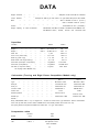
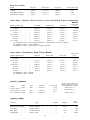
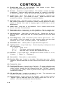
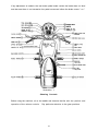
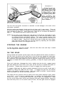
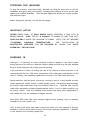
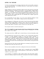
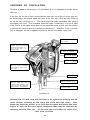
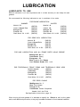
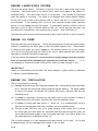
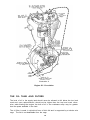
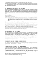
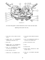


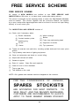
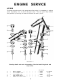


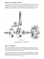
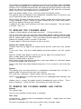

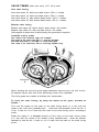
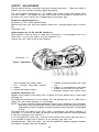
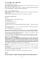
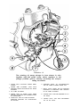
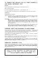

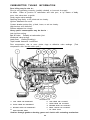
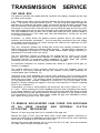
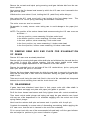
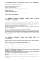
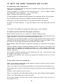
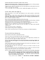

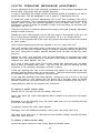
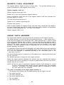

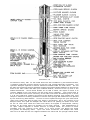
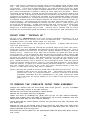
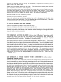
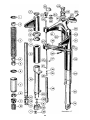
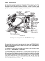
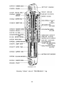

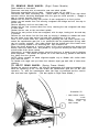

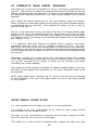

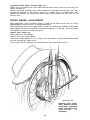
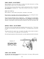
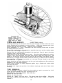
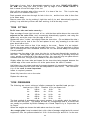

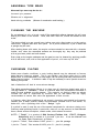
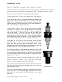
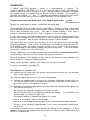
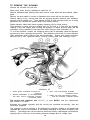
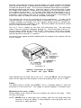
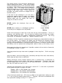
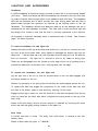
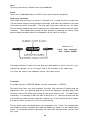
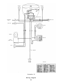
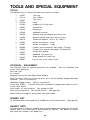
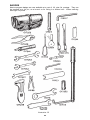
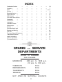


![General design guidance [PDF 950KB]](http://vs1.manualzilla.com/store/data/005804077_1-5fec14441b6361d04901f77e13b8a9c0-150x150.png)