1
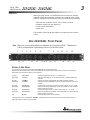
2-Way, 3-Way
4-Way Crossovers
223/223XL - 234/234XL
Operation
Manual
®
IMPORTANT SAFETY INSTRUCTIONS
WARNING FOR YOUR PROTECTION
READ THESE INSTRUCTIONS:
CAUTION
RISK OF ELECTRIC SHOCK
DO NOT OPEN
KEEP THESE INSTRUCTIONS
A T T E N T I O N : RISQUE DE CHOC ELECTRIQUE - NE PAS OUVRIR
W A R N I N G : TO REDUCE THE RISK OF FIRE OR ELECTRIC
HEED ALL WARNINGS
FOLLOW ALL INSTRUCTIONS
SHOCK DO NOT EXPOSE THIS EQUIPMENT TO RAIN OR MOISTURE
DO NOT USE THIS APPARATUS NEAR WATER
The symbols shown above are internationally accepted symbols that warn of potential hazards with
electrical products. The lightning flash with arrowpoint in an equilateral triangle means that there
are dangerous voltages present within the unit. The exclamation point in an equilateral triangle indicates that it is necessary for the user to refer to the owner’s manual.
CLEAN ONLY WITH A DRY CLOTH.
DO NOT BLOCK ANY OF THE VENTILATION OPENINGS. INSTALL IN ACCORDANCE WITH THE MANUFACTURER’S INSTRUCTIONS.
These symbols warn that there are no user serviceable parts inside the unit. Do not open the unit.
DO NOT INSTALL NEAR ANY HEAT SOURCES SUCH AS RADIATORS, HEAT REGISTERS, STOVES, OR
OTHER APPARATUS (INCLUDING AMPLIFIERS) THAT PRODUCE HEAT.
Do not attempt to service the unit yourself. Refer all servicing to qualified personnel. Opening the
chassis for any reason will void the manufacturer’s warranty. Do not get the unit wet. If liquid is
spilled on the unit, shut it off immediately and take it to a dealer for service. Disconnect the unit dur-
ONLY USE ATTACHMENTS/ACCESSORIES SPECIFIED BY THE MANUFACTURER.
ing storms to prevent damage.
UNPLUG THIS APPARATUS DURING LIGHTNING STORMS OR WHEN UNUSED FOR LONG PERIODS OF
TIME.
SAFETY INSTRUCTIONS
Do not defeat the safety purpose of the polarized or grounding-type plug. A polarized plug has
two blades with one wider than the other. A grounding type plug has two blades and a third
grounding prong. The wide blade or third prong are provided for your safety. If the provided
plug does not fit your outlet, consult an electrician for replacement of the obsolete outlet.
NOTICE FOR CUSTOMERS IF YOUR UNIT IS EQUIPPED WITH A POWER CORD.
Protect the power cord from being walked on or pinched particularly at plugs, convenience
receptacles, and the point where they exit from the apparatus.
WARNING: THIS APPLIANCE MUST BE EARTHED.
The cores in the mains lead are coloured in accordance with the following code:
GREEN and YELLOW - Earth
BLUE - Neutral
BROWN - Live
Use only with the cart stand, tripod bracket, or table specified by the manufacture, or sold with
the apparatus. When a cart is used, use caution when moving the cart/apparatus combination
to avoid injury from tip-over.
As colours of the cores in the mains lead of this appliance may not correspond with the coloured markings
identifying the terminals in your plug, proceed as follows:
• The core which is coloured green and yellow must be connected to the terminal in the plug
marked with the letter E, or with the earth symbol, or coloured green, or green and yellow.
• The core which is coloured blue must be connected to the terminal marked N or coloured black.
• The core which is coloured brown must be connected to the terminal marked L or coloured red.
This equipment may require the use of a different line cord, attachment plug, or both, depending on the
available power source at installation. If the attachment plug needs to be changed, refer servicing to qualified service personnel who should refer to the table below. The green/yellow wire shall be connected
directly to the units chassis.
CONDUCTOR
WIRE COLOR
Normal
Alt
BLACK
L
LIVE
BROWN
N
NEUTRAL
BLUE
E EARTH GND GREEN/YEL
WHITE
GREEN
WARNING: If the ground is defeated, certain fault conditions in the unit or in the system to which it is connected can result in full line voltage between chassis and earth ground. Severe injury or death can then
result if the chassis and earth ground are touched simultaneously.
Refer all servicing to to qualified service personnel. Servicing is required when the apparatus has been damaged in any way, such as power-supply cord or plug is damaged, liquid has
been spilled or objects have fallen into the apparatus, the apparatus has been exposed to rain
or moisture, does not operate normally, or has been dropped.
POWER ON/OFF SWITCH: For products provided with a power switch, the power switch DOES
NOT break the connection from the mains.
MAINS DISCONNECT: The plug shall remain readily operable. For rack-mount or installation
where plug is not accessible, an all-pole mains switch with a contact separation of at least 3
mm in each pole shall be incorporated into the electrical installation of the rack or building.
FOR UNITS EQUIPPED WITH EXTERNALLY ACCESSIBLE FUSE RECEPTACLE: Replace fuse with same
type and rating only.
MULTIPLE-INPUT VOLTAGE: This equipment may require the use of a different line cord, attachment plug, or both, depending on the available power source at installation. Connect this equipment only to the power source indicated on the equipment rear panel. To reduce the risk of fire
or electric shock, refer servicing to qualified service personnel or equivalent.
This Equipment is intended for rack mount use only.
IMPORTANT SAFETY INSTRUCTIONS
LITHIUM BATTERY
WARNING
CAUTION!
This product may contain a lithium battery.There is danger of
explosion if the battery is incorrectly replaced. Replace only
with an Eveready CR 2032 or equivalent. Make sure the battery is installed with the correct polarity. Discard used batteries according to manufacturer’s instructions.
ADVARSEL!
Lithiumbatteri - Eksplosjonsfare.Ved utskifting benyttes kun
batteri som anbefalt av apparatfabrikanten. Brukt batteri
returneres apparatleverandøren.
ADVARSEL!
Lithiumbatteri - Eksplosionsfare ved fejlagtig håndtering.
Udskiftning må kun ske med batteri av samme fabrikat og
type. Levér det brugte batteri tilbage til leverandøren.
VAROITUS!
Paristo voi räjähtää, jos se on virheellisesti asennettu.Vaihda
paristo ainoastaan laitevalmistajan suosittelemaan tyyppin.
Hävitä käytetty paristo valmistajan ohjeiden mukaisesti.
VARNING!
Explosionsfara vid felaktigt batteribyte. Använd samma batterityp eller en ekvivalent typ som rekommenderas av apparattillverkaren. Kassera använt batteri enligt fabrikantens instruktion.
ELECTROMAGNETIC
COMPATIBILITY
This unit conforms to the Product
Specifications noted on the Declaration of
Conformity. Operation is subject to the following two conditions:
• this device may not cause harmful interference, and
• this device must accept any interference
received, including interference that may
cause undesired operation.
Operation of this unit within significant electromagnetic fields should be avoided.
• use only shielded interconnecting cables.
U.K. MAINS PLUG WARNING
A molded mains plug that has been cut off from the cord is unsafe.
Discard the mains plug at a suitable disposal facility. NEVER UNDER
ANY CIRCUMSTANCES SHOULD YOU INSERT A DAMAGED OR CUT
MAINS PLUG INTO A 13 AMP POWER SOCKET. Do not use the
mains plug without the fuse cover in place. Replacement fuse covers
can be obtained from your local retailer. Replacement fuses are 13
amps and MUST be ASTA approved to BS1362.
DECLARATION OF
CONFORMITY
Manufacturer’s Name:
Manufacturer’s Address:
dbx Professional Products
8760 S. Sandy Parkway
Sandy, Utah 84070, USA
declares that the product:
Product name:
dbx223, 234, 223XL and 234XL
Note: Product name may be suffixed by the letters-EU or V.
Product option:
None
conforms to the following Product Specifications:
Safety:
IEC 60065 (1998)
EMC:
EN 55013 (1990)
EN 55020 (1991)
Supplementary Information:
The product herewith complies with the requirements of the Low
Voltage Directive 73/23/EEC and the EMC Directive 89/336/EEC as
amended by Directive 93/68/EEC.
Vice-President of Engineering
8760 S. Sandy Parkway
Sandy, Utah 84070, USA
6/23/03
European Contact: Your local dbx Sales and Service Office or
Harman Music Group
8760 South Sandy Parkway
Sandy, Utah 84070, USA
Ph: (801) 566-8800
Fax: (801) 568-7583
2-Way, 3-Way
4-Way Crossovers
223/223XL - 234/234XL
1
TABLE OF CONTENTS
WARRANTY ...............................................................................................................................................................2
INTRODUCTION .......................................................................................................................................................2
INSPECTION ........................................................................................................................................................................3
234/234XL FRONT PANEL OPERATION .............................................................................................................................3
223/223XL FRONT PANEL OPERATION .............................................................................................................................5
234/234XL-223/223XL REAR PANEL OPERATIONS ........................................................................................................6
234/234XL-223/223XL AUDIO CONNECTIONS ...................................................................................................................7
ELECTRICAL CONNECTIONS .............................................................................................................................................7
FEATURES ...........................................................................................................................................................................7
RACK MOUNTING, GROUNDING AND SAFETY ...............................................................................................................8
TROUBLESHOOTING ..........................................................................................................................................................9
234/234XL-223/223XL SPECIFICATIONS ..........................................................................................................................11
2
223/223XL - 234/234XL
1. The warranty registration card that accompanies this product must be
mailed within 30 days after purchase date to validate this warranty.
Proof-of-purchase is considered to be the burden of the consumer.
2-Way, 3-Way
4-Way Crossovers
WARRANTY
2. dbx warrants this product, when bought and used solely within the
U.S., to be free from defects in materials and workmanship under normal use and service.
3. dbx liability under this warranty is limited to repairing or, at our discretion, replacing defective materials that show evidence of defect, provided the product is returned to dbx WITH RETURN AUTHORIZATION
from the factory, where all parts and labor will be covered up to a period of two years. A Return Authorization number must be obtained from
dbx by telephone. The company shall not be liable for any consequential damage as a result of the product's use in any circuit or assembly.
4. dbx reserves the right to make changes in design or make additions to
or improvements upon this product without incurring any obligation to
install the same additions or improvements on products previously
manufactured.
5. The foregoing is in lieu of all other warranties, expressed or implied,
and dbx neither assumes nor authorizes any person to assume on its
behalf any obligation or liability in connection with the sale of this product. In no event shall dbx or its dealers be liable for special or consequential damages or from any delay in the performance of this warranty due to causes beyond their control.
Congratulations on your purchase of the dbx 223/223XL or 234/234XL
crossover. We are confident you will find this crossover to be the finest
product of its kind in this price range. We have taken care to include all of
the features you need to make your system sound its best. Some of the
features common to both the 234/234XL and the 223/223XL crossovers
are:
• back panel switches for selecting the operating mode of the
crossover.
• back panel switches indicating the selected range of crossover frequencies. Both of these features have LED indicators on the front
panel so you can see at a glance which mode the unit is in.
• low frequency summed output designed specifically for mono subwoofer applications.
• phase invert switches on all outputs.
• individual level controls on every output.
We are sure you will agree that these crossovers are built to provide
extremely high quality frequency division for all applications.
®
INTRODUCTION
2-Way, 3-Way
4-Way Crossovers
3
223/223XL - 234/234XL
INSPECTION
Before going any further, you should take time to fill out your warranty
registration card and inspect the contents of the shipping carton. Inside
both the 223/223XL and 234/234XL boxes you should find the following:
•
•
•
•
either the dbx model 223, 223XL, 234 or 234XL crossover.
operation manual (you are reading it!)
4 rack screws and washers
power cord.
The contents of this manual are subject to change at any time without
notice.
dbx 234/234XL Front Panel
Note: There are no front panel differences between the 234 and the 234XL. Therefore the
234XL is shown below, representing both the 234 and the 234XL.
1
2
13
3
4
14
5
15
6
16
17 18 19
7
8
20
9
21
10
22
11
12
23
24
STEREO 2-WAY MODE
In 2-way stereo mode the controls are marked BELOW the horizontal blue line.
Channel One and Channel Two functions are identical in the stereo mode. Front panel controls not described in
this section are not active in stereo 2-way operation.
[1] & [7]
[13] & [20]
INPUT GAIN
LOW CUT
[2] & [8]
[14] & [21]
LOW/MID*
X10 LED
[4] & [10]
[15] & [22]
LOW OUTPUT
PHASE INVERT
[6] & [12]
[17] & [24]
HIGH OUTPUT
PHASE INVERT
[19]
STEREO
Controls the INPUT level with +/- 12 dB of gain.
Switch for selecting the 40 Hz high pass filter. An LED indicates the
selection.
Selects crossover point between the LOW and HIGH outputs.
Indicates that the LOW/HIGH crossover frequency range is 450 Hz to
9.6 kHz.
Controls the Low frequency output level with a range of -∞ to +6 dB.
Switch for reversing the polarity on the Low Output. An LED indicates
that the phase is inverted.
Controls the High frequency output with a range of -∞ to +6 dB.
Switch for reversing the polarity on the High Output. An LED indicates
that the phase is inverted.
LED indicating stereo mode operation.
* although this control is labeled as “LOW/MID”, it operates as the crossover frequency control between low and
high frequencies in stereo 2-way operation.
®
4
223/223XL - 234/234XL
1
2
3
4
5
6
7
8
9
10
2-Way, 3-Way
4-Way Crossovers
11
12
234/234XL-223/223XL REAR
PANEL OPERATIONS
13
14
15
16
17 18 19
20
21
22
23
24
STEREO 3-WAY MODE
In 3-way stereo operation the controls are marked BELOW the horizontal blue line.
Channel One and Channel Two functions are identical in the stereo mode. LEDs are disabled for controls which are nonfunctional in this mode.
[1] & [7]
[13] & [20]
INPUT GAIN
LOW CUT
[2] & [8]
[14] & [21]
[3] & [9]
[4] & [10]
[15] & [22]
LOW/MID
X10 LED
MID/HIGH
LOW OUTPUT
PHASE INVERT
[5] & [11]
[16] & [23]
MID OUTPUT
PHASE INVERT
[6] & [12]
[17] & [24]
HIGH OUTPUT
PHASE INVERT
[19]
STEREO
Controls the INPUT level with +/- 12 dB of gain.
Switch for selecting the 40 Hz high pass filter. An LED indicates the selection.
Selects crossover point between LOW and MID frequencies.
Indicates that the LOW/MID crossover frequency range is 450 Hz to 9.6 kHz.
Selects crossover point between MID and HIGH frequencies.
Controls the Low Frequency output level with a range of -∞ to +6 dB.
Switch for reversing the polarity on the Low Output. An LED indicates the
selection.
Controls the Mid Frequency output with a range of -∞ to +6 dB.
Switch for reversing the polarity on the Mid Output. An LED indicates the
selection.
Controls the High Frequency output with a range of -∞ to +6 dB.
Switch for reversing the polarity on the High output. An LED indicates the
selection.
LED indicating stereo mode operation.
MONO 4 -WAY MODE
In 4-way mono operation the controls are marked ABOVE the horizontal blue line. Front panel controls not described in
this section are not active in mono 4-way mode. LEDs are disabled for controls which are non-functional in mono 4-way
mode.
[1]
[13]
INPUT GAIN
LOW CUT
Controls the input level with +/- 12 dB of gain.
Switch for selecting the 40 Hz high pass filter. An LED indicates the
selection.
Selects crossover point between LOW and LOW-MID frequencies.
LOW/LOW-MID
X10 LED
Indicates that the LOW/LOW-MID crossover frequency range is 450 Hz to
9.6 kHz.
LOW-MID/HIGH-MIDSelects the crossover point between LOW-MID and HIGH-MID frequencies.
HIGH-MID/HIGH
Selects the crossover point between HIGH-MID and HIGH frequencies.
LOW OUTPUT
Controls the LOW frequency output level with a range of -∞ to +6 dB.
Switch for reversing the polarity on the Low Output. An LED indicates the
PHASE INVERT
selection.
Controls the LOW-MID frequency output level with a range of -∞ to +6 dB.
LOW-MID OUTPUT
PHASE INVERT
Switch for reversing the polarity on the Low-Mid Output. An LED indicates
the selection.
Controls the HIGH-MID frequency output level with a range of -∞ to +6 dB.
HIGH-MID OUTPUT
PHASE INVERT
Switch for reversing the polarity on the High-Mid Output. An LED indicates
the selection.
HIGH OUTPUT
Controls the HIGH frequency output level with a range of -∞ to +6 dB.
PHASE INVERT
Switch for reversing the polarity on the High Output. An LED indicates
the selection.
LED indicating mono mode operation.
MONO
[2]
[14]
[3]
[9]
[4]
[15]
[5]
[16]
[11]
[23]
[12]
[24]
[18]
®
2-Way, 3-Way
4-Way Crossovers
5
223/223XL - 234/234XL
dbx 223/223XL Front Panel
Note: There are no front panel differences between the 223 and the 223XL. Therefore the
223XL is shown below, representing both the 223 and the 223XL.
1
2
9
3
10
11
4
12 13
5
14
6
15
7
16
8
17
18
STEREO 2-WAY MODE
In 2-way stereo mode the controls are marked BELOW the horizontal blue line.
Channel One and Channel Two functions are identical in the stereo mode. LEDs are disabled for controls which
are non-functional in this mode.
[1] & [5]
[9] & [15]
INPUT GAIN
LOW CUT
[2] & [6]
[10] & [16]
LOW/HIGH
X10 LED
[3] & [7]
LOW OUTPUT
[11] & [17]
PHASE INVERT
[4] & [8]
[12] & [18]
HIGH OUTPUT
PHASE INVERT
[14]
STEREO
Controls the INPUT level with +/- 12 dB of gain.
Switch for selecting the 40 Hz high pass filter. An LED indicates
the selection.
Selects crossover point between the LOW and HIGH outputs.
Indicates that the LOW/HIGH crossover frequency range is 450
Hz to 9.6 kHz.
Controls the Low Frequency output level with a range of -∞ to +6
dB.
Switch for reversing the polarity on the Low Output. An LED indicates the selection.
Controls the High Frequency output with a range of -∞ to +6 dB.
Switch for reversing the polarity on the High Output. An LED indicates the selection.
LED indicating stereo mode operation.
MONO 3 -WAY MODE
In 3-way mono operation the controls are marked ABOVE the horizontal blue line. Front panel controls not
described in this section are not active in mono 3-way mode. LEDs are disabled for controls which are nonfunctional in this mode.
[1]
[9]
INPUT GAIN
LOW CUT
[2]
[10]
[6]
[16]
LOW/MID
X10 LED
MID/HIGH
X10 LED
[3]
LOW OUTPUT
[11]
PHASE INVERT
[7]
MID OUTPUT
[17]
PHASE INVERT
[8]
HIGH OUTPUT
[18]
PHASE INVERT
[13]
MONO
Controls the input level with +/- 12 dB of gain.
Switch for selecting the 40 Hz high pass filter. An LED indicates
the selection.
Selects crossover point between LOW and MID frequencies.
Indicates that the LOW/MID crossover range is 450 Hz to 9.6 kHz.
Selects the crossover point between MID and HIGH frequencies.
Indicates that the MID/HIGH crossover frequency range is 450 Hz
to 9.6 kHz
Controls the LOW frequency output level with a range of -∞ to +6
dB.
Switch for reversing the polarity on the Low Output. An LED indicates that the phase is reversed.
Controls the MID frequency output level with a range of -∞ to +6
dB.
Switch for reversing the polarity on the Mid Output. An LED indicates that the phase is reversed.
Controls the HIGH frequency output level with a range of -∞ to +6
dB.
Switch for reversing the polarity on the High Output. An LED indicates that the phase is reversed.
LED indicating mono mode operation.
®
6
223/223XL - 234/234XL
The mode switches on the back panel of the unit are used to select one
of the three modes of operation in the 234/234XL and one of two modes
of operation in the 223/223XL. There could be disastrous consequences
if the crossover were improperly setup or the switches were mistakenly
pushed during the regular operation of a sound system. Therefore great
2-Way, 3-Way
4-Way Crossovers
234/234XL-223/223XL REAR
PANEL OPERATIONS
MODE SWITCHES
care should be taken when setting these switches. There is a mode diagram on the back panel to help you understand at a glance how this is
done. The following steps should be taken in setting up your system:
• Know the loudspeaker manufacturer’s requirements regarding the
amplification needs of your particular speaker system. Follow the
manufacturer’s guidelines carefully, as dbx is not responsible for damage relating to improper setup or implementation of the 234/234XL223/223XL.
• Without any audio or power connections in place, use the back panel
switches on the crossover to set it to the proper mode of operation;
either stereo 2-way, stereo 3-way, or mono 4-way for the 234/234XL,
or stereo 2-way or mono 3-way for the 223/223XL.
• Use the literature that came with your speaker system to properly set
up the mode of operation and crossover frequencies to the manufacturer’s specifications.
• There is one of the four possible mode button combinations for the
234/234XL which is marked “not valid”. Be sure you have not selected
this combination as the 234/234XL will not operate correctly in this
mode.
234XL REAR PANEL
234 REAR PANEL
When you are certain that the proper selections have been made, complete the steps described below and in the “234/234XL-223/223XL Audio
Connections” section on page 7.
®
2-Way, 3-Way
4-Way Crossovers
7
223/223XL - 234/234XL
On the back panel of the 234/234XL, there are markings to help you connect the source devices and amplifiers to your crossover. To operate the
234/234XL in stereo 3-way operation, follow the top row of markings horizontally along the length of the 234/234XL. For stereo 2-way operation of
the 234/234XL, use the second row of markings directly above the connectors. For mono 4-way operation of the 234/234XL, use the markings
directly below the connectors. The connectors not used in the selected
mode are marked “not used”. This designation applies only to that mode
223XL REAR PANEL
of operation.
223 REAR PANEL
The 223/223XL is marked in a similar way: for stereo 2-way operation use
the markings above the connectors. To operate the 223/223XL in mono 3way mode use the markings below the connectors. The connectors which
are not used in the selected mode are marked “not used”. This designation applies only to that mode of operation.
234/234XL-223/223XL
AUDIO CONNECTIONS
• Before connecting anything to the crossover, make sure it is not connected to any power source.
• Be sure that the source device (equalizer, compressor, mixing console,
etc.) for the 234/234XL-223/223XL is turned off. Connect the output(s) of
the source device to the inputs of the crossover, following the rear panel
markings carefully.
• Make sure that the amplifiers which will be used to drive your speaker
system are turned off. Using the back panel markings as a guide, use
high quality cables to connect the amplifiers to the appropriate outputs
of the 234/234XL-223/223XL.
ELECTRICAL CONNECTIONS
Ensure that your 234/234XL-223/223XL crossover conforms to the AC
power specifications in your area, by checking the marked voltage spec
on the rear of the unit. Never plug the incorrect voltage into your
®
8
223/223XL - 234/234XL
2-Way, 3-Way
4-Way Crossovers
crossover, as this may cause severe damage not covered under the dbx
warranty. Connect the power cord to the crossover first, then to a power
source that is properly grounded. Never lift the ground as a shock hazard
may result.
After you have safely plugged in the crossover, turn on the source
device(s). Turn the amplifiers’ outputs all the way down (-∞) and turn on
the amplifiers. All of the elements of your sound system should now be
on, and the amplifiers should be turned all the way down. Turn the source
device to its nominal operating level, sending a nominal (average) level to
the 234/234XL-223/223XL. Slowly turn up the amplifiers’ outputs until you
can hear signal at a comfortable volume. Make adjustments as you
desire.
FEATURES
X10
OPERATION
If you are using your system in stereo 2-way or 3-way mode, the needed
crossover frequency may be higher than 960 Hz, making it necessary to
set the x10 switch to the active position. This changes the range of operation of the frequency selector from 45-960 Hz to 450 Hz to 9.6 kHz. All
other frequency selectors remain the same. When using the X10 switch,
ALWAYS ensure that the amplifiers feeding all speaker systems are
turned off or that the input gain controls on the power amplifiers are
turned down before changing the setting of the X10 switch. Not doing so
may send a spurious signal to the outputs of the crossover when the X10
switch is engaged, and may damage speaker systems which are powered
at the time of the spurious signal.
Every output is equipped with a polarity (Ø) reverse switch on the front
panel. When speakers are not “in phase”, the frequency response of the
system is compromised, particularly in the low frequencies. Out of phase
signals can also cause “comb-filtering” in the high frequencies. The polarity switch is extremely useful for fine tuning your sound system for peak
performance. An LED is activated when the output polarity is reversed.
The other feature accessed on the back panel is “low frequency summing”. This is useful with systems that utilize mono subwoofers.
Activating the LF sum switch “sums” the low frequencies of both the left
and right inputs. The sum is sent to channel one’s low output marked “LF
SUM”, while channel two’s low output is not used, and channel two’s
phase invert led is disabled, indicating it is not operational in “LF Sum”
mode. The summed low frequencies represent all the low frequencies of
both the left and right inputs, and since lows are generally non-directional
®
POLARITY SWITCH
LOW FREQUENCY SUMMING
2-Way, 3-Way
4-Way Crossovers
9
223/223XL - 234/234XL
anyway, it will not detract from the true stereo picture of the source
material.
RACK MOUNTING, GROUNDING
AND SAFETY
We have provided 4 rack screws and washers for easy mounting in standard audio racks. You should avoid mounting the unit near large power
transformers or motors. Route the AC cord away from audio lines and
plug it into a power source close by. If the power cord must cross over
audio lines, you should take care to have them cross at 90 degree
angles.
The input and output connectors are balanced/unbalanced 1/ 4” TRStype connectors. The tip of the plug is wired as hot (+), the ring is wired
as cold (-), and the sleeve is wired as the ground or shield.
The 234/234XL-223/223XL crossovers have differentially balanced input
and output circuits. Balanced wiring is recommended, even with unbalanced source devices, especially when running long paths. Twin-conductor, shielded cable is more reliable since it does not depend on the shield
wire itself to complete the signal connection. Using twin conductor cable,
a broken shield may only result in a slight increase in noise or hum due to
the lack of shielding. You may also use unbalanced cables to connect to
and from the crossover.
TROUBLESHOOTING
NO SOUND
If there appears to be no power:
• Check that either the stereo or mono LED on the front panel of the
234/234XL-223/223XL is lit.
• Check that the power cord is seated properly in the back panel of the
crossover and that it is plugged into an active AC power source.
If there appears to be power, but no audible signal:
• Confirm that active audio lines are connected to the crossover’s
inputs and outputs.
• Check that both the input and output gain controls are advanced sufficiently.
• Check to make sure that you have turned up the amplifiers’ outputs.
ABNORMAL AUDIO OUTPUT
• Ensure that the proper mode for your setup has been selected via the
rear panel mode switches.
• Check the LF Sum switch.
• Check the x10 switch. This changes the range of the crossover frequency from 45 - 960 Hz to 450 Hz - 9.6 kHz.
®
10
223/223XL - 234/234XL
WEAK
2-Way, 3-Way
4-Way Crossovers
AND/OR DISTORTED AUDIO
• Check that a clean signal is being fed to the crossover.
• Confirm that the input wiring is correct.
• Check that the grounds of the audio signal path and the chassis and
power line of all units in the system are connected.
HUM
AND/OR BUZZ
If you suspect that the hum is caused by a ground loop:
• Systematically remove and/or connect the audio grounds of the devices
in the signal path.
• Remember, for safety you must maintain connection to chassis ground.
Never lift a safety ground.
If you suspect the hum is not caused by a ground loop.
• Check the audio at an earlier stage in the audio chain.
• Low level equipment should be mounted away from power amplifiers to
avoid induction of this type of hum.
• Be certain that all audio wiring except for loudspeaker lines is well shielded, and that low level wiring is not run parallel to and/or in close proximity
to AC power wiring.
• Check the other equipment and the wiring to make certain that the signal
is not intermittent earlier in the chain.
• Check the integrity of all cables using a cable tester.
®
INTERMITTENT AUDIO
2-Way, 3-Way
4-Way Crossovers
11
223/223XL - 234/234XL
dbx234/234XL- 223/223XL
SPECIFICATIONS
INPUT:
Connectors:
Type:
Impedance:
Max Input Level:
CMRR:
1/4” TRS (223/234) or XLR (223XL/234XL)
Electronically balanced/unbalanced, RF filtered
Balanced > 50 kΩ, unbalanced > 25 kΩ
+22 dBu typical, balanced or unbalanced
>40 dB, typically > 55 dB at 1 kHz
OUTPUT (223/234):
Connectors:
Type:
Impedance:
Max Output Level:
1/4” TRS
Impedance-balanced/unbalanced, RF filtered
Balanced 200 Ω, unbalanced 100 Ω
>+21 dBu balanced/unbalanced into 2 kΩ or greater
OUTPUT (223XL/234XL):
Connectors:
Type:
Impedance:
Max Output Level:
XLR
Electronically-balanced/unbalanced, RF filtered
Balanced 60 Ω, unbalanced 30 Ω
>+20 dBu balanced/unbalanced into 600Ω or greater
PERFORMANCE:
Bandwidth:
Frequency Response:
Signal-to-Noise:
234/234XL: Low Output:
Low-Mid Output:
Mid Output:
High-Mid Output:
High Output:
223/223XL: Low Output:
Mid Output:
High Output:
Dynamic Range:
THD+Noise:
Interchannel Crosstalk:
20 Hz to 20 kHz, +0/-0.5 dB
< 3 Hz to > 90 kHz, +0/-3 dB
Ref: +4 dBu, 22 kHz measurement bandwidth
Stereo Mode:
Mono Mode:
> 94 dB
> 94 dB
> 94 dB
> 93 dB
> 92 dB
> 90 dB
> 88 dB
> 94 dB
> 94 dB
> 93 dB
> 91 dB
> 91 dB
> 106 dB, unweighted, any output
< 0.004% at +4 dBu, 1 kHz
< 0.04% at +20 dBu, 1 kHz
< -80 dB, 20 Hz to 20 kHz
CROSSOVER FREQUENCIES:
234/234XL: Stereo Mode:
Low/High:
Low/Mid:
Mid/High:
234/234XL: Mono Mode:
Low/Low-Mid:
Low-Mid/High-Mid:
High-Mid/High:
223/223XL: Stereo Mode:
Low/High:
223/223XL: Mono Mode:
Low/Mid:
Mid/High:
Filter Type:
45 to 960 Hz or 450 Hz to 9.6 kHz (x10 setting)
45 to 960 Hz or 450 Hz to 9.6 kHz (x10 setting)
450 Hz to 9.6 kHz
45 to 960 Hz or 450 Hz to 9.6 kHz (x10 setting)
450 Hz to 9.6 kHz
450 Hz to 9.6 kHz
45 to 960 Hz or 450 Hz to 9.6 kHz (x10 setting)
45 to 960 Hz or 450 Hz to 9.6 kHz (x10 setting)
45 to 960 Hz or 450 Hz to 9.6 kHz (x10 setting)
Linkwitz-Riley, 24 dB/octave, state-variable
FUNCTION SWITCHES:
Front Panel:
Low Cut:
Phase Invert:
Rear Panel:
x10:
Mode:
LF Sum:
Activates 40 Hz Butterworth, 12 dB/octave high-pass
filter, one switch per channel.
Inverts the phase at the output, one switch per output.
Multiplies crossover frequency range by 10, one switch per channel.
Selects stereo/mono and 2/3/4-way operation.
Selects normal (stereo) or mono-summed low frequency operation.
INDICATORS:
Stereo Operation:
Mono Operation:
Low Cut:
x10:
Phase Invert:
Green LED
Yellow LED
Red LED per channel
Green LED per channel
Red LED per output (3 per channel)
POWER SUPPLY:
Operating Voltage:
Power Consumption:
Mains Connection:
100 VAC 50/60 Hz, 120 VAC 60 Hz
230 VAC 50/60 Hz
15 Watts
IEC 320 receptacle
PHYSICAL:
Dimensions:
Weight:
Shipping Weight:
Note: Specifications subject to change.
1.75” H X 19” W X 6.9” D (4.4cm x 48.3cm x 17.5cm)
234: 4.0 lbs. (1.8 kg) 223: 3.7 lbs. (1.7 kg)
234: 5.8 lbs. (2.6 kg) 223: 5.4 lbs. (2.5 kg)
®
®
8760 South Sandy Pkwy.
Sandy, Utah 84070
Phone: (801) 568-7660
Fax: (801) 568-7662
A Harman International Company
Questions or comments?
E•mail us at: [email protected]
or visit our World Wide Web home page at:
http://www.dbxpro.com
18-2155V-E
6/23/04
Printed In China