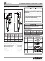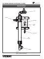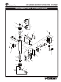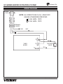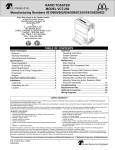
1
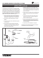
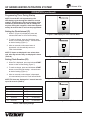
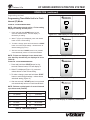
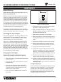
Manufacturing
Numbers:
9700430
9700432
9700433
Water filtration
system
UF-216/224 Series
P/N 1010808 Rev. E 03/12
Owner ’s Manual
UF SERIES water Filtration system
A.J. Antunes & Co.
Table of contents
Owner Information......................................................2
General.......................................................................2
Warranty Information..................................................2
Important Safety Information.....................................3
Service/Technical Assistance.....................................3
Electrical Cord & Plug Configurations........................5
Specifications..............................................................5
Electrical Ratings........................................................5
Dimensions.................................................................5
Specifications (Filter Cartridges)................................5
Specifications..............................................................6
Installation....................................................................7
Unpacking...................................................................7
Equipment Setup........................................................7
Locating and Mounting the system............................8
Filtration Process......................................................11
LED Display..............................................................11
Operation.................................................................... 11
Starting the System..................................................11
Programming Timer During Startup..........................12
Setting the Flush Interval (FI)...................................12
Setting Flush Duration (FD)......................................12
Checking the Timer Program....................................14
Changing the Cartridges..........................................14
Maintenance...............................................................14
Manual Flushing.......................................................14
Troubleshooting........................................................15
Replacement Parts UF-216/224................................16
Wiring Diagram..........................................................18
Notes..........................................................................19
LIMITED WARRANTY................................Back Cover
Owner Information
General
Warranty Information
VIZION of A.J. Antunes & Co., has partnered with
companies from around the globe to produce the UF
Series water filtration systems. The UF Series removes
bacteria and provides a substantial reduction of viruses
that can enter a typical water supply. This patented
technology is now available to you, sized for your particular application. All filter configurations utilize NeoH
capillary membranes, providing the latest innovation in
reusable surface filtration technology.
Please read the full text of the Limited Warranty in this
manual.
This manual provides the safety, installation and
operating procedures for the UF-Series water filtration
systems. We recommend that all information contained
in this manual be read prior to installing and operating
the unit.
• Damages caused in shipment or damage as
result of improper use.
• Installation of electrical service.
• Normal maintenance as outlined in this manual.
• Malfunction resulting from improper maintenance.
• Damage from moisture leaking into electrical
components.
• Normal maintenance as outlined in this manual.
• Damage from tampering with, removal of, or
changing any preset control or safety device.
If the unit arrives damaged, contact the carrier immediately and file a damage claim with them. Save all
packing materials when filing a claim. Freight damage
claims are the responsibility of the purchaser and are
not covered under warranty.
The warranty does NOT extend to:
Your UF-Series unit is manufactured from the finest
materials available and is assembled to our strict
quality standards. This unit has been tested at the
factory to ensure dependable trouble-free operation.
Important! Keep these instructions for future reference. If the unit changes
ownership, be sure this manual accompanies the equipment.
2
P/N 1010808 Rev. E 03/12
UF SERIES water filtration system
A.J. Antunes & Co.
Owner information (continued)
Service/Technical Assistance
Purchased From:
If you experience any problems with the installation
or operation of your unit, contact A.J. Antunes & Co.
at 1-630-784-1000, or toll free in the United States at
1-800-253-2991.
Date of Purchase:
Model No.:
Serial No.:
Fill in the information in the next column and have it
handy when calling for assistance. The serial number
is on the specification plate located on the unit.
Mfg. No.:
Important
A.J. Antunes and Company reserves the right to change specifications and product
design without notice. Such revisions do NOT entitle the buyer to corresponding
changes, improvements, additions or replacements for previously purchased equipment.
Important Safety Information
In addition to the warnings and cautions in this manual,
use the following guidelines for safe operation of the
unit.
Throughout this manual, you will find the following
safety words and symbols that signify important safety
issues with regards to operating or maintaining the unit.
Warning
GENERAL WARNING. Indicates information important to the proper operation of
the equipment. Failure to observe may
result in damage to the equipment and/or
severe bodily injury or death.
Warning
ELECTRICAL WARNING. Indicates information relating to possible shock hazard.
Failure to observe may result in damage
to the equipment and/or severe bodily
injury or death.
Caution
GENERAL CAUTION. Indicates information important to the proper operation of
the equipment. Failure to observe may
result in damage to the equipment.
P/N 1010808 Rev. E 03/12
3
• Read all instructions before using equipment.
• For your safety, the equipment is furnished with
a properly grounded cord connector. Do NOT
attempt to defeat the grounded connector.
• Install or locate the equipment only for its intended use as described in this manual. Do NOT use
corrosive chemicals in this equipment.
• Do NOT operate this equipment if it has a damaged cord or plug; if it is not working properly, or
if it has been damaged or dropped.
• This equipment should be serviced by qualified
personnel only. Contact A.J. Antunes & Co. for
repair.
• Do NOT immerse cord or plug in water.
• Keep cord away from heated surfaces.
UF SERIES water Filtration system
A.J. Antunes & Co.
Important safety information (continued)
The following warnings and cautions appear throughout
this manual and should be carefully observed.
- Do NOT use an extension cord with this unit.
- Check with a qualified electrician if you are
unsure if the appliance is properly grounded.
• Turn the power off and unplug the power cord
before performing any service or maintenance on
the unit.
• The equipment should be grounded according to
local electrical codes to prevent the possibility of
electrical shock. It requires a grounded receptacle
with separate electrical lines, protected by fuses
or circuit breaker of the proper rating.
• All electrical connections must be in accordance
with local electrical codes and any other applicable codes.
• Warning electrical shock hazard. Failure to follow these instructions
could result in serious injury or death.
• If the supply cord is damaged, it must be
replaced by the manufacturer or its service agent
or a similarly qualified person.
• This equipment is to be installed to comply with
the local plumbing code and any other applicable
code.
• Water pressure must not exceed the membrane
burst pressure of 7 bar (100 psi). To reduce
water pressure, install a water pressure regulator
and set water pressure to suit application. Note
that trans membrane pressure (inlet water pressure minus the permeate water pressure) must
be .5 - 2.5 bar (7 - 36 psi).
-Electrical ground is required on this unit.
- Do NOT modify the power supply cord plug. If it does not fit the outlet, have a proper outlet
installed by a qualified electrician.
4
P/N 1010808 Rev. E 03/12
UF SERIES water filtration system
A.J. Antunes & Co.
Specifications
Dimensions
Warning
ELECTRICAL SHOCK HAZARD.
Failure to follow the instructions in
this manual could result in serious injury or death.
B
A
• Electrical ground is required on this appliance.
• Do NOT modify the power supply cord plug. If
it does not fit the outlet, have a proper outlet
installed by a qualified electrician.
• Do NOT use an extension cord with this unit.
• Check with a qualified electrician if you are
unsure if the appliance is properly grounded.
C
Caution
All electrical connections must be in accordance
with local electrical codes and any other
applicable codes.
Electrical Ratings
Voltage
Watts
Hertz
120
10
50/60
230
10
50/60
Model
No.
Width
(A)
Depth
(B)
Height
(C)
Operating
Weight
(w/water)
UF-216
10 3/8”
(26 cm)
4 13/16”
(12 cm)
25 15/16”
(66 cm)
8 lbs.
(3.6 kg)
Letter
Code*
UF-224
10 3/8”
(26 cm)
4 13/16”
(12 cm)
33 15/16”
(86 cm)
12 lbs.
(5.4 kg)
C
Electrical Cord & Plug Configurations
H
(H)C**
Specifications (Filter Cartridges)
Maximum Operating Pressure
Maximum Operating Temp.
Trans Membrane Pressure
pH Range
MWCO
Sanitizing Temp.
7 bar (100 psi)
40°C (104°F)
0.5-2.5 Bar (7-36 psi)
3-10
100 kD
80°C (176°F)
(C)F***
(H)K
Description
Configuration
Commercial Cord
Harmonized Cord
CEE 7/7, 16 Amp.,
250 VAC (Assembly
Only).
5-15P, 15 Amp., 120
VAC., Non – Locking
(Assembly Only).
GRN
WHT BLK
Chinese/Australian,
10 Amp., 250 VAC.
(Assembly only)
* Used in Model Designation
** Indicates that the Plug comes with a Harmonized Cord
** Indicates that the Plug comes with a Commercial Cord
P/N 1010808 Rev. E 03/12
5
UF SERIES water Filtration system
A.J. Antunes & Co.
Specifications
Components
Drain
Permeate
LED Display
Program
Button
Power Cord
Filter
Cartridge
Strainer
Inlet
Figure 1. System Components
6
P/N 1010808 Rev. E 03/12
UF SERIES water filtration system
A.J. Antunes & Co.
Installation
Unpacking
Do NOT over tighten the connections. It is recommended
that plastic fittings be used when connecting to the
plastic connections of the system. This will reduce the
possibility of cracking the connections due to overtightening.
1. Remove the system and all packing materials
from the shipping carton.
2. Remove all packing materials and protective
coverings from the system
If soldered plumbing is used, do not apply heat to, or
near, the filtration system. The use of union (O-ring
seal) connections is highly recommended for ease of
installation and future servicing.
3. Remove the information packet. To prevent any
delay in obtaining warranty coverage, fill out and
mail the warranty card.
NOTE: If any parts are damaged, contact A.J.
Antunes & Co. IMMEDIATELY at 1-800-253-2991 or
1-630-784-1000.
Suggested Tools and Supplies for Installation
The following tools and supplies are suggested to make
the installation easier:
Equipment Setup
•
•
•
•
•
•
General
When placing the unit into service, pay attention to the
following guidelines:
• Make sure power to the unit is off.
• Do NOT immerse cord or plug in water.
• Keep cord away from heated surfaces.
Screwdriver
Drill with bits
Strap wrench
(up to 6” diameter)
Tape measure
Two gallon bucket
Fresh 5 1/4% liq-
uid chlorine bleach
•
•
•
•
Adjustable wrenches
Pipe wrenches
Level
Pipe dope or thread seal tape
Electrical
Ensure that the line voltage corresponds to the stated
voltage on the units specification label. Make sure that
the plug on the power cord from the system and the
outlet match. For proper operation, and to ensure the
highest quality water from the system, make sure that
the system is not connected to a switched electrical
outlet.
Caution
This equipment is to be installed to comply with
the basic plumbing code of the Building Officials
and Code Administrators, Inc. (BOCA) and the
Food Service Sanitation Manual of the Food and
Drug Administration (FDA).
Plumbing
Caution
Water pressure must not exceed a membrane
burst pressure of 7 bar (100 psi). To reduce water
pressure, install a water pressure regulator and
set water pressure to suit application. Note that
the trans membrane pressure must be .5 - 2.5 bar
(7 - 36 psi).
NOTE: This unit is designed to use tap water not to
exceed 104°F (40°C).
The UF-216 uses the following connections (Figure 1):
•
•
•
Water Inlet Permeate (Product Water)
Drain 1/2” NPT
1/2” NPT
1/2” NPT
When making a plumbing connection to the system,
remember to use a back-up wrench on the supporting
plumbing. Always use a good quality, approved, pipe
sealant or thread seal tape on pipe threads. Be careful
not to get the pipe sealant inside the pipe when making
the connections.
P/N 1010808 Rev. E 03/12
7
UF SERIES water Filtration system
A.J. Antunes & Co.
Installation (continued)
Locating and Mounting the system
Permeate Line Plumbing
Consider these points before mounting the system:
To ensure the highest quality and safest water, it is
recommended that a check valve (to prevent backflow)
be installed in the water line after the permeate connection. This will help prevent possible contamination of the
filter system due to other equipment downstream. The
check valve (not supplied) should be mounted close to
the system outlet, and sized properly for the plumbing
line. Check with local codes for the proper specification.
• Note the location of the water supply, drain, and
an appropriate electrical outlet when choosing a
mounting location.
• Remember to allow for access to the timer/
programmer controls.
• Do NOT mount the system above any electrical
equipment, or items that may be damaged if they
get wet.
Drain line plumbing
The drain line is used to flush away the particle buildup
when cleaning the filter. The drain line must be able to
support the flow rate when the system flushes. The flow
rate from the flush depends on the inlet water pressure,
inlet pipe size, and system selected. It is recommended
that the drain line be as large as, or larger than, the
inlet plumbing line. The drain line should be as short as
possible, sloping downward without kinks or loops. Be
sure that the drain used is not blocked or restricted.
• Install the system in a location that will allow for
future service access.
• Mount the system on a wall using appropriate
mounting hardware.
• Remember to consider the operating weight of
the system when choosing mounting hardware.
Depending on the type of wall the system is being
mounted to, wall reinforcement may be necessary.
The filter system must be protected from possible back
contamination by the installation of an air gap between
the drain connection of the system and the drain
(Figure 3). This gap in the line, with no physical contact
between the system and sewer, prevents contamination
of the system in the event of a backed-up sewer.
Mount the filtration unit using the Mounting Bracket
(Figure 2) using 1/4” by 1” bolts or bolts of the metric
equivalent.
Inlet Water Plumbing
It is recommended that the inlet water plumbing line
be 3/4” NPT or larger. A shutoff valve (not supplied)
should be installed in the line leading to the system.
The valve should be mounted close to the system inlet
and sized properly for the inlet plumbing line. This
valve will allow for easier servicing and future cartridge
change-out. The system should only be connected to
the cold water line.
NOTE: Make sure that the end of the drain line is
positioned and secured at least 2 inches above
the drain so that the water flow is directed into the
drain, without splashing.
To ensure that the highest quality water is produced
from the system, the plumbing leading to the filter
system must be flushed clear of all debris before the
system is hooked up. Before making the connection to
the inlet of the filter system, hold a bucket or other container at the inlet water line and slowly open the inlet
water valved. Allow the pipe to flush until all debris is
removed.
6 7/8"
(17.5 cm)
9 3/4"
(24.8 cm)
Figure 2. Mounting Bracket (Front View)
8
P/N 1010808 Rev. E 03/12
UF SERIES water filtration system
A.J. Antunes & Co.
Installation (continued)
4. Press and hold the Start button. After 6-7 seconds, the drain valve will open and FL will appear
on the display.
Flushing and starting the system
To ensure that the highest quality water is produced
from the system, the plumbing leading from the filter
system must be flushed clear of all debris after the system is hooked up. After making the connection to the
outlet of the filter system, open a faucet or tap closest
to the filter system, then slowly open the inlet water
valve. Allow the pipe to flush until all debris is removed.
5. Continue holding the Start button down for at
least 30 seconds to keep the drain open. This
flushes air out of the center of the hollow fibers.
The drain will remain open as long as the Start
button is pressed. Check to make sure that the
drain water is directed into the drain without
splashing.
The unit also must be flushed to remove air and the
shipping/storage solution. For maximum quality, the
permeate water produced during the flushing procedure
must be discarded. Direct this permeate water to drain. 6. Release the Start button. This closes the drain
valve. Water should continue to flow through the
system and out of the open tap. Allow water to
flow out of the tap for at least 15 minutes at maximum flow rate.
NOTE: Ultra Filter Cartridge must be rinsed to drain
before use. Rinsing to drain removes storage solution
and air. Do NOT rinse into carbon if present. Carbon
life and/or performance may be affected.
7. Close the tap and let the system stand with no
water flow for 15 minutes to allow any trapped air
to come out of the hollow fibers. Check for leaks
at all fittings.
1. Plug the power cord into the appropriate electrical outlet. The display will power on and the LED
display will display the following for about two seconds each:
•
•
•
8. After 15 minutes without water flow, open the
tap for 5 minutes to allow any trapped air to be
flushed out.
8.8
F8 followed by its time settings in seconds
Fi and its time setting in minutes or hours.
9. Close the tap. Flushing is complete.
The F8 and Fi sequence repeats for 30 seconds
after which the unit automatically returns to the
Flush Interval Mode (Fi). The time setting for Fi will
be displayed and the decimal point will flash in one
second intervals.
2. Open the tap or faucet closest downstream to the
filter system.
3. Slowly open the inlet water valve and allow water
to enter the system.
P/N 1010808 Rev. E 03/12
9
UF SERIES water Filtration system
A.J. Antunes & Co.
Installation (continued)
5. When the water flow out of the strainer stops,
pour the liquid bleach into the strainer. Be careful
not to spill bleach onto clothing or skin. You may
want to add the bleach using a cup. Reattach the
cap on the strainer.
Sanitizing the System and Lines
The plumbing must be sanitized to eliminate possible
contamination that may have occurred during the installation process. Chlorine bleach can be used to sanitize
the plumbing. The amount of bleach to use depends on
the system installed and the amount of plumbing downstream of the filter system. Generally, 1 or 2 cap fulls of
bleach will be sufficient to sanitize the system.
6. Slowly open the inlet water valve and allow water
to flow out of the tap until the smell of bleach is
present.
1. Make sure that the system has been flushed of
air and debris as described in the Flushing and
Starting up the System section of this manual.
7. Close the tap and let the system stand with no
water flow for at least 15 minutes to allow the
bleach to sanitize the pipes.
2. Open the tap closest downstream to the filter
system.
8. After 15 minutes without flow, open the tap and
flush until the presence of bleach is gone. All
other taps should be opened to flush any bleach
from the plumbing.
3. Close the inlet water valve and allow the system
to depressurize.
9. Close the tap. The sanitization is complete.
4. Place a bucket under the strainer at the inlet
connection to the system. Open the strainer by
unscrewing the cap. Water will flow out of the
strainer as the system drains.
Program the timer following the procedure outlined in
the Operation section of this manual.
Drain Line
from System
Secure
End
Drain Line
from System
2” (5.1 cm)
minimum
Secure
End
Standpipe
2” (5.1 cm)
minimum
Floor
Drain
Drain
Figure 3. Proper Draining
10
P/N 1010808 Rev. E 03/12
A.J. Antunes & Co.
UF SERIES water filtration system
Operation
Filtration Process
Starting the System
Water filtration in the UF Series is accomplished using
two modes:
Power up the unit.
The LED read-out displays the following for about two
seconds each:
• Flush Interval (Fi on the LED display)
• Flush Duration (Fd on LED display).
1. 8.8
During the Flush Interval mode, water enters the inlet
and flows through the filter element before exiting the
Permeate outlet as usable product water. After a certain
period of time, depending upon water quality, the filter
has to be cleaned. This is accomplished through the
Flush Duration Mode. During this mode, the drain valve
opens and flushes the membrane to remove debris collected inside the membrane walls.
2. Fd followed by its time settings in seconds.
NOTE: Both the Flush Interval Mode and the Flush
Duration Mode can be automated by programming
the timer. During the Flush Interval Mode, the valve
is not powered in order to keep water filtering during
a power outage.
NOTE: The timer can be programmed immediately
after start-up or while in Flush Interval Mode.
3. Fi and its time setting, in minutes or hours.
The Fd and Fi sequence repeats for 30 seconds after which, the unit automatically returns to the Flush Interval Mode (Fi). The time setting for Fi
will be displayed and the decimal point will flash in one second intervals.
LED Display
Fi - Flush Interval Mode is the time between flushings and is displayed in minutes or hours.
Fd - Flush Duration Mode is the amount of time used to flush and remove debris from filter cartridge and is displayed in seconds.
FL - Manual Flush Mode operation, solenoid is
manually activated by the user.
P/N 1010808 Rev. E 03/12
Figure 4. LED Display, Front Panel
11
UF SERIES water Filtration system
A.J. Antunes & Co.
Operation (continued)
Programming Timer During Startup
NOTE: Once the UF unit is powered up, the
LED display cycles through the default or current
settings: Flush Duration (Fd) and its setting will be
followed by Flush Interval (Fi) and its settings. At
any time during this sequence, which lasts approximately 30 seconds the UF unit can be programmed.
Setting the Flush Interval (FI)
1. When Fi (Figure 4) is displayed, press and
release start button to view current setting .
Figure 5. LED Display for Flush Interval Mode
2. To make a change, press and hold down start
button to scroll through settings - release button
at desired setting (Figure 5).
3. After ten seconds, unless start button is
depressed, unit automatically returns to
Flush Interval Mode.
NOTE: Fi times are displayed in ten minute intervals, after fifty minutes they are displayed in hours
(Table A).
Figure 6. Time Setting Fi Mode (22 Hours)
Setting Flush Duration (FD)
2. When Fd is displayed, press and release start
button to view current setting (Figure 7).
3. To make a change, press and hold down start
button to scroll through settings - release button
at desired setting (Figure 8).
4. After ten seconds, unless button is depressed,
unit automatically returns to Flush Interval Mode.
Figure 7. LED Display for Flush Duration Mode
NOTE: Fd times are displayed in 5 second intervals
up to 60 seconds (Table A).
Fi - Flush Interval Mode
Fd - Flush Duration Mode
1-
10 minutes
5
5 seconds
5- 50 Minutes 10
10 seconds
01 1 Hour
15
15 Seconds
12
12 Hours
30
30 Seconds
24
24 hours
60 60 Seconds
Figure 8. Time Setting Fd Mode (55 Seconds)
Table A. LED Display Settings
12
P/N 1010808 Rev. E 03/12
UF SERIES water filtration system
A.J. Antunes & Co.
Operation (continued)
Programming continued
Programming Timer While Unit is in Flush
Interval (FI) Mode
TO SET FI - FLUSH INTERVAL MODE
NOTE: After power-up and cycling - Fi time setting
displays a flashing decimal point.
1. Press and hold down start button for four
seconds. Release button, LED will display Fd
followed by its setting.
Figure 9. Fi - LED Display for Flush Interval Mode
2. When Fi (Figure 9) is displayed, press and release
button to view current setting.
3. To make a change, press and hold down the start
button to scroll through settings - release button at
desired setting (Figure 10).
4. After ten seconds, if start button is not pressed,
unit automatically returns to Flush Interval Mode.
Figure 10. Time display for Fi Mode (30 Minutes)
NOTE: Fi times are displayed in ten minute intervals, after fifty minutes they are displayed in hours
(Table B).
TO SET FD - FLUSH DURATION MODE
1. Press and hold down start button for four
seconds. Release button, LED will display Fd.
2. When Fd is displayed (Figure 11), press and release button to view current setting.
3. To make a change, press and hold down start
button to scroll through settings - release button
at desired setting (Figure 12).
Figure 11. LED Display for Flush Duration
4. After ten seconds, if start button is not pressed
unit automatically returns to Flush Interval Mode.
NOTE: Fd times are displayed in 5 second intervals
up to 60 seconds (Table B).
Fi - Flush Interval Mode
Fd - Flush Duration Mode
1-
10 minutes
5
5 seconds
5-
50 Minutes
10
10 seconds
01 1 Hour
15
15 Seconds
12
12 Hours
30
30 Seconds
24
24 hours
60 60 Seconds
Figure 12. Time Display for Fd Mode (15 Seconds)
Table B. LED Display Settings
P/N 1010808 Rev. E 03/12
13
UF SERIES water Filtration system
A.J. Antunes & Co.
Maintenance
Manual Flushing
NOTE: Manual flushing only works when unit is in
Flush Interval Mode (Fi).
While the unit is in Flush Interval Mode (decimal point
flashing), hold the start button down for 6-7 seconds
until the LED displays FL (Figure 13). Continue holding the button down to keep the drain open. Drain will
remain open for as long as start button is depressed.
(FL will flash on LED.) Releasing the button closes the
drain and puts the unit back into startup mode. After ten
seconds, if the start button is not pressed the unit automatically returns to the Flush Interval Mode (Fi).
Figure 13. Manual Flush
5. Reattach the cap on the strainer when the water
flow stops. Unplug the power cord.
The filtration system is designed to require very little
maintenance. To ensure that the water is of the highest
quality, occasionally some service is required.
6. Using a strap wrench (up to 6” capacity), loosen
the top and bottom end caps. Do NOT remove the
top and bottom End Caps yet.
Checking the Timer Program
7. Disconnect the permeate port connection.
During normal operation, the system displays the time
setting for the Flush Interval Mode (FI) and the decimal will flash in one second intervals. This is the time
between flushing, not a time of day setting.
8. Using a screwdriver, remove the screws from the
cartridge bracket and set the bracket and screws
aside.
9. Unscrew the cartridge end caps from the cartridge.
Over time, it is possible that the time that the system
flushes occurs at a time of high water use. If that creates a problem, the timer can be reset by unplugging
the power cord, waiting for 5 seconds, and plugging the
power cord in again. The timer then begins timing from
the point power is restored to the system. Follow the
procedures within the Operation section of this manual
to check and set the timer settings.
10. Install a new cartridge to the system using the
cartridge bracket and screws saved from Step 8.
11. Connect the permeate port connection.
Changing the Cartridges
12. Inspect the O-rings to make sure they are clean
and are not splitting or cut. For all O-rings, make
sure they are lubricated with an approved food
grade lubricant acceptable for drinking water use.
While the filtration system is designed for long life,
eventually the cartridges will need to be replaced.
13. For each end cap, screw the cap onto the cartridge. Tighten with strap wrench as necessary.
1. Open the faucet or tap closest downstream to the
filtration system.
14. Follow the Flushing and Starting the System and
Sanitizing the System and Lines procedures in the
Installation section of this manual to complete the
cartridge change.
2. Close the inlet water valve and allow the system
to depressurize.
System sanitization
3. Place a bucket under the strainer at the inlet
connection to the system. Open the strainer by
unscrewing the cap. Water will flow out of the
strainer as the system drains.
Over time and use, the plumbing downstream from the
system may require sanitization. It is recommended
that the system and downstream plumbing be sanitized at least once a year. When necessary, follow
the Sanitizing the System and Lines procedure in the
Installation section of this manual.
4. Press and hold the Start button to help drain
the system.
14
P/N 1010808 Rev. E 03/12
UF SERIES water filtration system
A.J. Antunes & Co.
Troubleshooting
Problem
Possible Cause
Corrective Action
Unit does not have power.
The power cord is not correctly
plugged in.
Plug power cord in correctly.
The Control Display is blank.
The power cord is not correctly
plugged in.
Plug power cord in correctly.
Control Board is inoperable.
Transformer is inoperable.
Contact your maintenance person or
Authorized Service agency.
Inlet Valve closed
Open the Inlet Valve
Inlet Strainer is plugged
Clean/replace Inlet Strainer
End of the capillaries plugged
Clean/replace Filter Cartridge
See above.
See above.
The system may be in a flush cycle.
Wait for the flush cycle to end.
Flushing program not set correctly
for water conditions.
Decrease the flush interval and increase
the flush duration (refer to the Operation
section of this manual).
Drain Valve is stuck open.
Replace/rebuild the Drain Valve.
The inlet water pressure is too low.
Boost the inlet water pressure/replace
pipes.
Storage/shipping solution not completely flushed out of system.
Flush system for a longer period of time.
Biological growth in pipes.
Sanitize plumbing.
Water conditions changed.
Consider installing taste and odor filtration.
Broken capillary in Filter Cartridge.
Replace Filter Cartridge.
Drain Valve stuck open.
Replace/rebuild the Drain Valve.
Controller sending continuous signal
to valve.
Replace the controller.
Flush runs too long.
Program duration set too long.
Re-program the unit to flush for a shorter
duration of time.
Flush occurs at time of high
water usage.
The Flush Interval is set to interfere
with water use.
Change Flush Interval/reprogram time.
Unplug unit and plug in at a time of lower
water usage.
Water splashes at drain during flush.
Drain line not positioned properly.
Reposition the end of the drain line.
Water leaks at the ends of the
Filter Cartridge after changing
cartridges.
Cartridge end connections are not
tight enough.
Tighten with strap wrench if necessary.
O-rings not lubricated.
Lubricate O-rings with food-grade lubricant.
O-rings are split, cut, or twisted
Replace O-rings.
Permeate port is not tight enough
Tighten, with strap wrench if necessary.
O-ring not lubricated.
Lubricate O-ring with food-grade lubricant.
O-ring split, cut, or twisted.
Replace O-ring.
Fitting broken or loose.
Retighten or replace the fitting.
Not enough pipe thread sealant
used.
Redo the fitting with the proper amount of
sealant.
No water comes out of the
filter system
Low water flow/pressure out
of system
Water tastes bad.
Flush runs continuously.
Water leaks from Permeate
port.
Water leaks from system fitting or connection.
P/N 1010808 Rev. E 03/12
15
UF SERIES water Filtration system
A.J. Antunes & Co.
Replacement Parts UF-216/224
Item
Part
No.
1 7000432
7000433
2 1001116
3 0700463
0700634
0700354
Description
Timer, 120V (For Mfg. # 9700430)
Timer, 230V (For Mfg. # 9700432)
Label, Timer
Power Cord 5-15P (CF)
(For Mfg. #s 9700430 )
Power Cord CEE 7/7 (HC)
(For Mfg. # 9700432)
Power Cord Chinese/Australian,
10 Amp., 250 VAC. (Assembly only)
(for Mfg. # 9700433 only)
4 040K251 Strain Relief, Power Cord
5 4060355 Terminal Block
6 0503983 Control Housing
7 7000359 Cover Gasket Kit
8 7000362 Cover, Control Housing Kit (Incl. Items 2 & 7)
9 4040187 Solenoid Valve 120V
NC 1/2” NPT (For Mfg. # 9700430)
4040188 Solenoid Valve 230V
NC 1/2” NPT (For Mfg. # 9700432)
10 7000357 Solenoid Valve/Coil Kit 120 V
(For Mfg. # 9700430)
7000358 Solenoid Valve/Coil Kit 230V
(For Mfg. # 9700432)
Qty.
Item
Part
No.
13 0503981
14 0503984
15 2090120
16 2180173
17 2180177
18 0200219
19 2190133
20 2090129
21 0200225
22 2070124
23 2190117
24 7000360
26 7000361
28 1001101
29 308P157
30 308P143
31 306P101
32 304P105
33 308P124
34 306P123
1
1
1
1
1
1
1
1
1
1
1
1
1
1
Description
Clamp, Filter 2”
Mounting Bracket 2”
Cartridge, Filter 2” x 16” (For
Mfg. #s 9700430 and 9700432)
Connector, Slide 2”
Cap, End 2”
“O” Ring 2”
Tee Strainer 1/2” NPT
Screen, Tee Strainer 1/2” NPT
Gasket, Tee Strainer 1/2” NPT
Close Nipple 1/2” NPT
90° Elbow 1/4” NPT
Permeate Assy. Kit 2”
Strain Relif Kit
Label - Wiring Diagram
Screw Tap #8-32 x 3/8”
Nut Keps #8-32
Nut Hex #6-32
Nut Keps #4-40
One Way Screw #8-32
Screw #6-32 x 7/8”
Qty.
1
1
1
2
2
4
1
1
1
1
1
1
1
1
12
2
2
4
1
2
1
16
P/N 1010808 Rev. E 03/12
UF SERIES water filtration system
A.J. Antunes & Co.
Replacement parts UF-216/224 (continued)
10
22
23
17
9
18
26
28
14
25
16
33
29
24
34
13
30
6
31
32
4
15
5
8
1
29
3
7
18
16
29
2
17
21
20
19
P/N 1010808 Rev. E 03/12
17
UF SERIES water Filtration system
A.J. Antunes & Co.
Wiring Diagram
GRN-YEL
BLK/BRN
WHT/BLU
POWER
CORD
NOTE: ALL WIRED TO BE 16 GA.. AWM-105ºC
UNLESS OTHERWISE SPECIFIED
14 GA. AWM - 105ºC
22 GA. AWM - 105ºC
TERMINAL
BLOCK
GND
WHT
BLK
T2
TIMER
BOARD
RED
SOLENOID
VALVE
T3
T4
18
BLK
P/N 1010808 Rev. E 03/12
A.J. Antunes & Co.
UF SERIES water filtration system
Notes
P/N 1010808 Rev. E 03/12
19
Limited Warranty
Equipment manufactured by A.J. Antunes & Co. has been constructed of the finest materials available and manufactured to high quality standards. These units are warranted to be free from defects
in materials and workmanship for a period of one year from date of purchase under normal use and
service, and when installed in accordance with manufacturer’s recommendations*. The ultra filtration
membrane cartridge is warranted under the same terms and conditions on a prorated basis for 24
months from date of purchase.
*To ensure continued proper operation of the units, follow the maintenance procedure outlined in the
Owner’s Manual.
1. This warranty does not cover failures due to improper system installation, defects caused by improper
storage or handling prior to placing of the equipment into service. This warranty does not include
overtime charges or work done by unauthorized service agencies or personnel. This warranty does
not cover normal maintenance, calibration, or regular adjustments as specified in operating and maintenance instructions of this manual, and/or labor involved in moving adjacent objects to gain access to
the Equipment.
2. A.J. Antunes & Co. reserves the right to make changes in design or add any improvements on any
product. The right is always reserved to modify equipment because of factors beyond our control and
government regulations. Changes to update equipment do not constitute a warranty charge.
3.If shipment is damaged in transit, the purchaser should make a claim directly upon the carrier.
Careful inspection should be made of the shipment as soon as it arrives and visible damage should
be noted upon the carrier’s documentation. Damage should be reported to the carrier. This damage
is not covered under this warranty.
4.This warranty is exclusive and is in lieu of all other warranties, expressed or implied, including any implied warranty or merchantability or fitness for a particular purpose, each of which is hereby expressly disclaimed. The remedies described above are exclusive and in no event shall A.J. ANtunes & CO.
be liable for special consequential or incidental damages for the breach or delay in performance of this warranty.
Prices and specifications are subject to change without notice.