1
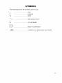
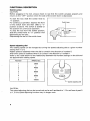
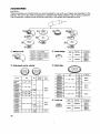
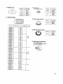
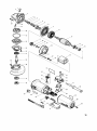
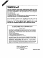
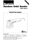
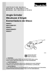
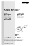
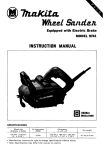
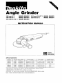
a
Angle Grinder
100 mm (4”)
100 mm (4”)
115 mm (4-112”)
MODEL 9 5 6 0 C V
MODEL 9 5 6 3 C V
MODEL 9 5 6 1 C V
115 mm (4-112”)
125 m m (5”)
MODEL 9 5 6 4 C V
MODEL 9 5 6 5 C V
INSTRUCTION MANUAL
DOUBLE
INSULATION
SPECIFICATIONS
MODEL
9560CV
9563CV
1
1
I
9561CV
___
9565CV
I
No load speed (RPM)
2,800
2,800
10,5001min
10,5001min.
~
2.800 -
10,5001min
2,800
10,50O/min.
~~
I
1
I
I
Overall lenqth
289
m m ( 1 1 318”)
2 9 9 mm ( 1 1 - 3 1 4 ” )
I
1
1
Net weiaht
1 7 k q ( 3 . 7 Ibs)
1 . 8 ka ( 4 . 0 Ibsl
1
I
1
Spindle thread
M I 0 x 1 25
M I 0 x 1.25
2 8 9 mm ( 1 1 318”)
1 7 k g ( 3 7 Ibs)
518”
2 9 9 mm ( 1 1-314”)
1 8 kg ( 4 . 0 Ibs)
518”
GENERAL SAFETY RULES
USAooz-i
(For All Tools)
WARNING! Read and understand all instructions. Failure
to follow all instructions listed below, may result in electric
shock, fire and/or serious personal injury.
SAVE THESE INSTRUCTIONS
Work Area
1. Keep your work area clean and well lit. Cluttered benches and dark areas invite
accidents.
2. Do not operate power tools in explosive atmospheres, such as in the presence
of flammable liquids, gases, or dust. Power tools create sparks which may
ignite the dust or fumes.
3.Keep bystanders, children, and visitors away while operating a power tool.
Distractions can cause you t o lose control.
Electrical Safety
4. Double Insulated tools are equipped w i t h a polarized plug (one blade is wider
than the other.) This plug will fit in a polarized outlet only one way. If the
plug does not fit fully in the outlet, reverse the plug. If it still does not fit,
contact a qualified electrician t o install a polarized outlet. Do not change
the plug in any way. Double insulation H eliminates the need for the three
wire grounded power cord and grounded power supply system.
5. Avoid body contact with grounded surfaces such as pipes, radiators, ranges
and refrigerators. There is an increased risk of electric shock if your body is
grounded.
6. Do not expose power tools t o rain or wet conditions. Water entering a power
tool will increase the risk of electric shock.
7. Do not abuse the cord. Never use the cord t o carry the tools or pull the plug
from an outlet. Keep cord away from heat, oil, sharp edges or moving parts.
Replace damaged cords immediately. Damaged cords increase the risk of
electric shock.
8. When operating a power tool outside, use an outdoor extension cord marked
"W-A" or "W." These cords are rated for outdoor use and reduce the risk
of electric shock.
Personal Safety
9. Stay alert, watch what you are doing and use common sense when operating
a power tool. Do not use tool while tired or under the influence of drugs,
alcohol, or medication. A moment of inattention while operating power tools
may result in serious personal injury.
10. Dress properly. Do not wear loose clothing or jewelry. Contain long hair. Keep
your hair, clothing, and gloves away from moving parts. Loose clothes, jewelry
or long hair can be caught in moving parts.
2
11. Avoid accidental starting. Be sure switch is off before plugging in. Carrying
tools with your finger on the switch or plugging in tools that have the switch
on invites accidents.
12. Remove adjusting keys or wrenches before turning the tool on. A wrench
or a key that is left attached to a rotating part of the tool may result in personal
injury.
13. Do not overreach. Keep proper footing and balance at all times. Proper footing
and balance enables better control of the tool in unexpected situations.
14. Use safety equipment. Always wear eye protection. Dust mask, nonskid
safety shoes, hard hat, or hearing protection must be used for appropriate
conditions.
Tool Use and Care
15. Use clamps or other practical way t o secure and support the workpiece t o
a stable platform. Holding the work by hand or against your body is unstable
and may lead t o loss of control.
16. Do not force tool. Use the correct tool for your application. The correct tool
will do the job better and safer at the rate for which it is designed.
17. Do not use tool if switch does not turn it on or off. Any tool that cannot
be controlled with the switch is dangerous and must be repaired.
18. Disconnect the plug from the power source before making any adjustments,
changing accessories, or storing the tool. Such preventive safety measures
reduce the risk of starting the tool accidentally.
19. Store idle tools out of reach of children and other untrained persons. Tools
are dangerous in the hands of untrained users.
20. Maintain tools w i t h care. Keep cutting tools sharp and clean. Properly
maintained tools, with sharp cutting edges are less likely t o bind and are easier
t o control.
21. Check for misalignment or binding of moving parts, breakage of parts, and
any other condition that may affect the tools operation. I f damaged, have
the tool serviced before using. Many accidents are caused by poorly
maintained tools.
22. Use only accessories that are recommended by the manufacturer for your
model. Accessories that may be suitable for one tool, may become hazardous
when used on another tool.
SERVICE
23. Tool service must be performed only by qualified repair personnel. Service
or maintenance performed by unqualified personnel could result in a risk of
injury.
24.,When servicing a tool, use only identical replacement parts. Follow
instructions i n the Maintenance section of this manual. Use of unauthorized
parts or failure to follow Maintenance Instructions may create a risk of electric
shock or injury.
3
Specific Safety Rules
USBOOS-l
1. Always use proper guard with grinding wheel. A guard protects operator from
broken wheel fragments.
2. Accessories must be rated for at least the speed recommended on the tool
warning label. Wheels and other accessories running over rated speed can
fly apart and cause injury.
3.Hold tool by insulated gripping surfaces when performing an operation where
the cutting tool may contact hidden wiring or its o w n cord. Contact with
a "live" wire will make exposed metal parts of the tool "live" and shock the
operator.
4. Keep guards in place.
5. Use only wheels having a maximum operating speed at least as high as "No
Load RPM" marked on the tool's nameplate. When using depressed center
wheels, be sure t o use only fiberglass-reinforced wheels.
6.Check the wheel carefully for cracks or damage before operation. Replace
cracked or damaged wheel immediately.
7. Use only flanges specified for this tool.
8. Be careful not t o damage the spindle, the flange (especially the installing
surface) or the lock nut. Damage t o these parts could result in wheel
breakage.
9. Hold the tool firmly.
IO. Keep hands away from rotating parts.
11. Make sure the wheel is not contacting the workpiece before the switch is
turned on.
12.Before using the tool on an actual workpiece, let it run for a while. Watch
for vibration or wobbling that could indicate poor installation or a poorly
balanced wheel.
13.Use the specified surface of the wheel t o perform the grinding.
14. Watch out for flying sparks. Hold the tool so that sparks fly away from you
and other persons or flammable materials.
15. Do not leave the tool running. Operate the tool only when hand-held.
16.Do not touch the workpiece immediately after operation; it may be extremely
hot and could burn your skin.
SAVE THESE INSTRUCTIONS.
4
SYMBOLS
The followings show the symbols used for tool.
v
volts
A
Hz
....................................
....................................
....................................
?
,.
....................................
alternating current
b
....................................
no load speed
H
....................................
Class II Construction
.../min ...................................
amperes
herts
revolutions or reciprocation per minute
5
FUNCTIONAL DESCRIPTION
Switch action
CAUTION:
Before plugging in the tool, always check to see that the switch actuates properly and
returns to the "OFF" position when the side of the switch lever is depressed.
To start the tool, slide the switch lever to
"I" position.
For continuous operation, depress the front
of the switch lever and then slide to "I"
position as above. The switch is locked on
the position for continuous operation.
To stop the tool from the locked position,
slide the switch lever to "0" position with
depressing its rear part.
Depressingthe rear of the switch lever.
Switch lever
Speed adjusting dial
The rotating speed can be changed by turning the speed adjusting dial to a given number
setting from 1 to 5 .
Higher speed is obtained when the dial is turned in the direction of number 5.
And lower speed is obtained when it is turned in the direction of number 1 .
Refer to the table below for the relationship between the number settings on the dial and
the approximate rotating speed.
II
Number
RPM (mid
2800
1
4000
1
6500
1
9000
1
10500
k 3 p e e d adjusting dial
CAUTION:
The speed adjusting dial can be turned only as far as 5 and back to 1. Do not force it past 5
or 1 , or the speed adjusting function may no longer work.
6
ASSEMBLY
Installing and removing wheel cover
Installing
Pull the lever in the direction of the arrow after loosening the screw.
Install the wheel cover on the bearing box by adjusting the convex of the wheel cover to
the concave of the bearing box.
Turn the wheel cover by 180 degrees. Fasten it with the screw after pulling the lever the
direction of the arrow.
For the working purpose, the setting angle of the wheel cover can be adjusted with the
lever
Removing wheel cover
Follow the installation procedure in reverse to remove the wheel cover
Installing side grip (auxiliary handle)
Screw the side grip on the tool securely.
The side grip can be installed on either side
of the tool, whichever is convenient.
Shaft lock
Press the shaft lock to prevent spindle rotation when installing or removing accessories.
Shaft lock
CAUTION:
Never actuate the shaft lock when the
spindle is moving. The tool may be damaged.
7
Installing or removing the depressed center wheel
CAUTION:
Always be sure that the tool is switched off and unplugged before installing or removing
the wheel.
Mount the inner flange onto the spindle. Fit
the wheel on over the inner flange and
screw the lock nut onto the spindle.
Lock nut
e
-a
Depressed
Inner flange
To tighten the lock nut, press the shaft lock
firmly so that the spindle cannot revolve,
then use the lock nut wrench and securely
tighten clockwise.
WARNING:
Only actuate the shaft lock when the spindle is not moving.
~
OPERATION
CAUTION:
After operation, always switch off the tool and wait until the wheel has come to a complete stop before putting the tool down.
Hold the tool firmly. Turn the tool on and
then apply the wheel or disc to the workpiece.
In general, keep the edge of the wheel or
disc at an angle of about 15" - 30" to the
workpiece surface.
During the break-in period with a new
wheel, do not work the grinder in the B
direction or it will cut into the workpiece.
Once the edge of the wheel has been
rounded off by use, the wheel may be
worked in both A and B direction.
8
-
~
-
~
_
_
_
-
WARN1NG:
It should never be necessary to force the tool. The weight of the tool applied adequate
pressure. Forcing and excessive pressure could cause dangerous when wheel breakage.
Continued use of a worn-out wheel may result in wheel explosion and serious personal
injury. Depressed center wheel should not be used after it has been worn down to
75 mm (3") in diameter for Models 9560CV, 9563CV or 90 mm (3-1/2") for Models
9561CV, 9564CV and 9565CV in diameter. Use of the wheel after this point is unsafe and
it should be removed from service and rendered unusable by intentional destruction.
The tools equipped with electronic function are easy to operate because of the following
features.
Electronic speed control for obtaining constant speed
Possible to get fine finish, because the rotating speed is kept constantly even under the
loaded condition.
Soft start feature
Safety and soft start because of suppressed starting shock.
Overload protector
When the tool would be employed over the admissible load, it will stop automatically to
protect the motor and wheel. When the load will come to the admissible level again, the
tool can be started automaticallv.
MAINTENANCE
CAUTION:
Always be sure that the tool is switched off and unplugged before attempting to perform
inspection or maintenance.
Repair and maintenance
The tool and its opening vents for cooling
air have to be always kept clean. When the
foreign matters clog such parts. they have
to be taken off.
I
Inhalation vent
To maintain product SAFETY and RELIABILITY, repairs, any other maintenance or adjustment should be performed by Makita Authorized or Factory Service Centers, always using
Makita replacement parts.
9
ACCESSORIES
CAUTION:
These accessories or attachments are recommendedfor use with your Makita tool specified in this
manual. The use of any other accessories or attachments might present a risk of injury to persons.
The accessories or attachments should be used only in the proper and intended manner.
@ Wheelcover
PanNo.
I
For Model
Q
Inner flange
I
Size
I
45
@ Depressed center wheels
Pan No.
741402-8
18ulk)
I
I
Size
I
I
Pat NO.
74203808
7420380C
9563cv
40
4-1/2" x 5B" x 7 W
7943314.4
5"X511)"X 7 8 "
@ Locknut
Size
mcv
74142481
5
5/8-45
1
9565CV
10
-
9561CV
9564cv
100
40
60
7
95650'
80
100
794331dD
41R" x 1 / 4 x 7 W
9563cv
100
M)
7943314C
24
-
794332-28
79433148
36
9560CV
80
4"xlWx518"
794332-20
7414258
=-
40
7
794332-2A
794332-2c
I
9561CV
9564CV
9565CV
For Model
Grit
Size
7420380D
741402C
7414W2P
I
224368-2
7420380A
Grit
4,,x3~16,,x5B,,
4x3/16"~518"
I For Model
@ Multi-disc
7414026-1
7414052-1
Part~o.
I
I
Part No.
224566-8
I
ForModel
1
9561cv
9564CV
9565cv
@
Rubberpad
(For abrasive disc)
Part No.
For Model
743036-3
9565CV
9565CV
743015-1
@ Abrasive discs
@ Wire cup brush 75
Part No
74203603
I
9565CV
Diameter
Per pkg
For Model
@ Wire bevel brush 85
9560CV
4'
9563CV
8 Wheel guard assembly
(For cut-off wheel)
For Model 9560CV. 9563CV
Part No. 192476-6
742087-0
7420400
7941 05-A-5
-1
794105-A-5
794106A-5
I
5
794 107-A-5
3561CV
4-1/2''
794104-8
3564CV
794107-8
794108-8
120
142072-A-5
24
742073-A-5
30
742074-A-5
50
742075-A-5
742076A-5
742072-8
742073-8
742074-8
742075-0
7420768
80
80
-
5"
5
120
E65CV
24
-
36
50
1
80
120
11
@ Cut-off wheel
Grit
Wheels per pkg.
For use
For Model
724104-110
Pan No.
4" x 3/32" x 5"'
Size
36
10
For masonry and concrete.
724107-510
4" x 5/64" x 5B"
46
10
For steel and cast iron.
9560cv
9563CV
Knot-Type
Wire cup brush
Knotted-Twist
Wire cup brush
9564CV
Pan No.
I
743212-A
I
Part No.
I
For Model
9561CV
9564CV
9565CV
Lock nut wrench
Stringer Bead Twist
Wire brush wheel
ForModel
0
9561CV
9565CV
743213-E
9565CV
Full Cable Twist
Wire brush wheel
Part No.
I
I
12
Grip
Part No. 152490-4
For Model
IV
+
57
56
55
54
50
48
G
47
@-
46
13
ITEM NO. DESCRIPTION
1
PIN CAP
2
COMPRESSION SPRING 8
3
GEAR HOUSING COMPLETE
HEX. NUT M6
4
FLAT WASHER 6
5
6
SPIRAL BEVEL GEAR 1 1
7
LOCK SPRING 12
RETAINING RING S-12
8
9
BALL BEARING 6001LLB
FLAT WASHER 12
10
GEAR HOUSING COVER
11
FAN 57
12
13
ARMATURE ASSY
INC. 12.14-16
INSULATION WASHER
14
FLAT WASHER 7
15
I6
BALL BEARING 627DDW
LABYRINTH RUBBER RING 22
17
MAGNET SLEEVE
18
STOP RING E-4
19
20
BAFFLE PLATE
21
TAPPING SCREW 4x60
RETAINER
22
INSULATION COVER
23
FIELD
24
TAPPING SCREW 4x18
25
STRAIN RELIEF
26
SWITCH BLOCK
27
SWITCH STll5A-40
28
COVER
29
SWITCH LEVER
30
COMPRESSION SPRING 4
31
14
NO USED
1
1
1
1
1
1
1
1
I
1
1
1
1
1
1
1
1
1
1
1
2
2
2
1
2
1
1
1
1
1
1
ITEM NO
32
33
34
35
36
37
38
39
40
41
42
43
44
45
46
41
48
49
50
51
52
53
54
55
56
57
58
59
BO
DESCRIPTION
NO USED
BRUSH HOLDER
1
MOTOR HOUSING
1
MAKITA LABEL
1
SWITCH KNOB
1
1
CORD GUARD 8
POWER SUPPLY CORD
1
REAR COVER
1
1
TAPPING SCREW 4x18
INDICATION LABEL
1
CONTROLLER
1
A C CARBON BRUSH CB-318
1
BRUSH HOLDER
1
TAPPING SCREW PT3XlO
4
NAME PLATE
1
LOCK NUT 10-35
1
INNER FLANGE 35
1
1
WHEEL COVER
PAN HEAD SCREW M5XI 6
1
1
SPINDLE
LABYRINTH RING
1
HEX. SOCKET HEAD BOLT M4X16
4
WHEEL COVER BASE
1
BEARING BOX COMPLETE
1
0 RING 52
1
SPIRAL BEVEL GEAR 38
1
PIN
1
0 RING 6
1
TAPPING SCREW 4x28
4
WAVE WASHER 6
1
Some dust created by power sanding, sawing, grinding, drilling, and other
construction activities contains chemicals known [to the State of Califomia] to
cause cancer, birth defects or other reproductive harm. Some examples of
these chemicals are:
0 Lead from lead-based paints,
0 Crystalline silica from bricks and cement and other masonry products, and
0 Arsenic and chromium from chemically-treated lumber.
Your risk from these exposures varies, depending on how often you do this
type of work. To reduce your exposure to these chemicals: work in a well
ventilated area, and work with approved safety equipment, such as those
dust masks that are specially designed to filter out microscopic particles.
MAKITA LIMED ONE YEAR WARRANTY
Warranty Policy
Every Makita tool is thoroughly inspected and tested before leaving the factory. It is warranted t o
be free of defects from workmanshlp and materials for the period of ONE YEAR from the date of
original purchase. Should any trouble develop during this one-year period. return the COMPLETE
tool, freight prepaid, to one of Makita’s Factory or Authorized Service Centers. If inspection shows
the trouble is caused by defective workmanship or material, Makita will repair (or at our option,
replace) without charge.
1
This Warranty does not apply where:
repairs have been made or attempted by others:
repairs are required because of normal wear and tear:
The tool has been abused, misused or improperly maintained;
alterations have been made to the tool.
IN NO EVENT SHALL MAKITA BE LIABLE FOR ANY INDIRECT, INCIDENTAL OR CONSEQUENTIAL DAMAGES FROM THE SALE OR USE O F THE PRODUCT. THIS DISCLAIMER
APPLIES BOTH DURING AND AFTER THE TERM O F THIS WARRANTY.
MAKITA DISCLAIMS LIABILITY FOR ANY IMPLIED WARRANTIES, INCLUDING IMPLIED
WARRANTIES O F “MERCHANTABILITY” AND “FITNESS FOR A SPECIFIC PURPOSE,”
AFTER THE ONE-YEAR TERM O F THIS WARRANTY.
This Warranty gives you specific legal rights, and you may also have other rights which vary from
state to state. Some states do not allow the exclusion or limitation of incidental or consequential
damages, so the above limitation or exclusion may not apply t o you. Some states d o not allow
limitation on how long an implied warranty lasts, so the above limitation may not apply to you.
Makita Corporation
3-11-8, Sumiyoshi-cho,
Anjo, Aichi 446-8502 Japan
884311A061
PRINTED IN JAPAN