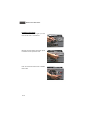
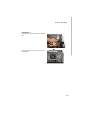
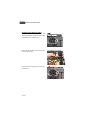
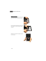
1
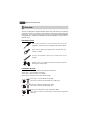
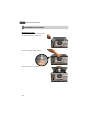
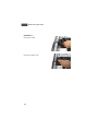
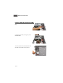
Saturn 900 / 945 Series
Saturn 900 / 945 Series
G52-64661X1
FCC-B Radio Frequency Interference Statement
This equipment has been tested and
found to comply with the limits for a
class B digital device, pursuant to
part 15 of the FCC rules. These limits
are designed to provide reasonable
protection against harmful interference in a residential installation. This equipment
generates, uses and can radiate radio frequency energy and, if not installed and
used in accordance with the instruction manual, may cause harmful interference to
radio communications. However, there is no guarantee that interference will not
occur in a particular installation. If this equipment does cause harmful interference to
radio or television reception, which can be determined by turning the equipment off
and on, the user is encouraged to try to correct the interference by one or more of the
measures listed below.
=Reorient or relocate the receiving antenna.
=Increase the separation between the equipment and receiver.
=Connec the equipment into an outlet on a circuit different from that to which the
receiver is connected.
=Consult the dealer or an experienced radio/television technician for help.
Notice 1
The changes or modifications not expressly approved by the party responsible for
compliance could void the user’s authority to operate the equipment.
Notice 2
Shielded interface cables and A.C. power cord, if any, must be used in order to
comply with the emission limits.
VOIR LA NOTICE D’INSTALLATION AVANT DE RACCORDER AU RESEAU.
Saturn 900 / 945 Series
This device complies with Part 15 of the FCC Rules. Operation is subject to the
following two conditions:
(1) this device may not cause harmful interference, and
(2) this device must accept any interference received, including interfer ence that
may cause undesired operation.
ii
Trademark
All trademarks are the properties of their respective owners.
Intel® and Pentium® are registered trademarks of Intel Corporation.
PS/2 and OS ® /2 are registered trademarks of International Business Machines
Corporation.
W indows ® 95/98/2000/NT/XP are registered trademarks of Microsoft Corporation.
Netware® is a registered trademark of Novell, Inc.
Award® is a registered trademark of Phoenix Technologies Ltd.
AMI® is a registered trademark of American Megatrends Inc.
U.S. Patent Numbers
4,631,603; 4,819,098; 4,907,093; 5,315,448; and 6,516,132.
This product incorporates copyright protection technology that is protected by U.S.
patents and other intellectual property rights. Use of this copyright protection technology must be authorized by Macrovision, and is intended for home and other limited
viewing uses only unless otherwise authorized by Macrovision. Reverse engineering
or disassembly is prohibited.
Revision History
Revision
Revision History
Date
V1.0
First Release
April 2007
iii
Safety Instructions
1.
Always read the safety instructions carefully.
2.
Keep this User’s Manual for future reference.
3.
Keep this equipment away from humidity.
4.
Lay this equipment on a reliable flat surface before setting it up.
5.
The openings on the enclosure are for air convection hence protects the
equipment from overheating. DO NOT COVER THE OPENINGS.
6.
Make sure the voltage of the power source and adjust properly 110/220V
before connecting the equipment to the power inlet. Rating: 110-120V / 220240V, 8/4.5A, 60/50Hz or 220-240V, 4A, 50Hz.
7.
Place the power cord such a way that people can not step on it. Do not
place anything over the power cord.
8.
Always Unplug the Power Cord before inserting any add-on card or module.
9.
All cautions and warnings on the equipment should be noted.
10.
Never pour any liquid into the opening that could damage or cause electrical
shock.
11.
If any of the following situations arises, get the equipment checked by service
personnel:
- The power cord or plug is damaged.
- Liquid has penetrated into the equipment.
- The equipment has been exposed to moisture.
- The equipment does not work well or you can not get it work according to
User’s Manual.
- The equipment has dropped and damaged.
- The equipment has obvious sign of breakage.
12.
DO NOT LEAVE THIS EQUIPMENT IN AN ENVIRONMENT UNCONDITIONED,
STORAGE TEMPERATURE ABOVE 400 C (1020F), IT MAY DAMAGE THE
EQUIPMENT.
CAUT ION:
Danger of explos ion if battery is inc orrec tly replac ed.
Replace only with the same or equivalent type recommended by the
manufacturer.
iv
Warning:
1. For every changes in powercord’s usage, please use an approved power
cord with condition greater or equal to H05VV-F,3G , 0.75mm2.
2. Internal part is hazardous moving parts, please keep fingers and other
body parts away.
3. For pluggable equipment, the socket-outlet shall be installed near the
equipment and shall be easily accessible.
4. Do not disable the protective earth pin from the plug, the equipment must
be connected to an earthed mains socket-outlet.
v
WEEE Statement
vi
vii
viii
CONTENTS
FCC-B Radio Frequency Interference Statement................................ii
Trademark......................................................................................iii
U.S. Patent Numbers......................................................................iii
Revision History..............................................................................iii
Safety Instructions..........................................................................iv
WEEE Statement...........................................................................vi
Chapter 1. Getting Started.........................................................1-1
System Configuration..............................................................1-2
Front View.......................................................................1-2
Back View.......................................................................1-3
Internal Placement............................................................1-4
Chapter 2. System Assembly......................................................2-1
Overview.................................................................................2-2
Installation Tools...............................................................2-2
Installation Screws............................................................2-2
Checking the Items...........................................................2-3
Installation Procedures............................................................2-4
Removing Covers..............................................................2-4
Installing Optical Disk Drive (ODD).....................................2-7
Installing Card Reader (CR) or Floppy Disk Drive (FDD).........2-9
Installing IDE Hard Disk Drive (HDD).................................2-10
Installing SATA Hard Disk Drive (HDD)...............................2-12
Installing PCI Card............................................................2-14
Installing PCI Express Card..............................................2-16
Restoring Covers...............................................................2-18
Complete Installation.........................................................2-21
ix
Chapter 1
Getting Started
Congratulations for purchasing MSI® Saturn 900 / 945
Series (MS-6469 / MS-6466). MSI® Saturn 900 / 945
Series is your best Mini-Tower PC choice.
ONLY FOR SERVICE PERSONEL
For more information about the built-in
mainboard's spec ific ation, ple ase re fe r
to the mainboard manual in the package.
Saturn 900 / 945 Series
System Configuration
Front View
1.
2.
3.
4.
5.25” Driver Bay (for ODD)
3.5” Driver Bay (for CR or FDD)
Headphone / Speaker (Green)
USB 2.0 Ports
5. M icrophone (Pink)
6. Power Button / Power LED
7. Reset Button
* This picture is for your reference only and may vary from the different item you
installed.
1-2
Getting Started
Back View
1.
2.
3.
4.
5.
6.
Voltage Selector
Power Jack
Power Switch
PS/2 M ouse (Green)
PS/2 Keyboard (Purple)
Serial Port
7. Parallel Port
8. VGA Port (D-Sub15)
9. LAN Jack (RJ45)
10. USB 2.0 Ports
11. Audio Jacks
12. Expansion Slots
* The Input/Output (I/O) part in this picture is for your reference only and may slightly
vary from the different mainboard you purchased.
1-3
Saturn 900 / 945 Series
Internal Placement
- Dimension: 190mm (W) x 350mm (H) x 380mm (D)
- Minimized screw structure
- Multiple ventilation design
- Detachable bay housing
Expansion Slots
Mainboard
System Fan
ATX Power Supply
3.5” Driver Bay 3.5” Driver Bay 5.25” Driver Bay
x2 (For HDD) x2 (For CR or FDD) x2 (For ODD)
MSI® Saturn 900 Series (MS-6469) Mini-Tower PC
with built-in (MS-7255) Micro-ATX Mainboard
1-4
Getting Started
Internal Placement
- Dimension: 190mm (W) x 350mm (H) x 380mm (D)
- Minimized screw structure
- Multiple ventilation design
- Detachable bay housing
Expansion Slots
Mainboard
System Fan
ATX Power Supply
3.5” Driver Bay 3.5” Driver Bay 5.25” Driver Bay
x2 (For HDD) x2 (For CR or FDD) x2 (For ODD)
MSI® Saturn 945 Series (MS-6466) Mini-Tower PC
with built-in (MS-7267) Micro-ATX Mainboard
1-5
System Assembly
Chapter 2
System Assembly
This chapter provides you with the information about
system assembly procedures. While doing the installation,
be careful in holding the components and follow the
installation procedures.
Use a grounded wrist strap before handling computer
c omp onents . Static elec tri c ity may damage the
components.
ONLY FOR SERVICE PERSONEL
Always unplug the power cord before
inserting any add-on card or module.
2-1
Saturn 900 / 945 Series
Overview
The built-in mainboard is designed for MSI® Saturn 900 / 945 Series only. Except the
mainboard, the built-in components of the barebone include ATX Power Supply and
System Fan. In this chapter, we will show you how to install Optical Disk Drive(ODD),
Card Reader(CR), Floppy Disk Drive(FDD), Hard Disk Drive(HDD), PCI Card and PCIExpress Card.
Installation Tools
Cross type s crewdriv er, c an be used to do mos t of the
installation. Choose one with a magnetic head would be better.
Pliers, can be used as an auxiliary tool to connect some connectors or cables.
Forceps, can be used to pick up tiny screws or set up the
jumpers.
Rubber gloves, can prevent yourself from being incised and
suffering the static charge.
Installation Screws
Three types of screws are used in assembling the barebone:
Screw type 1: Round-headed screw (M3)
Screw type 2: Button-headed screw (6#32)
Screw type 3: Hexagonal screw with washer (6#32)
Screw type 1: Round-headed screw (M3)
This screw is used to lock the ODD, CR or FDD (x16)
Screw type 2: Button-headed screw (6#32)
This screw is used to lock the HDD (x8)
Screw type 3: Hexagonal screw with washer (6#32)
This screw is used to lock the system covers and PCI expansion
slots (x9)
2-2
System Assembly
Checking the Items
Before assembling the system, please check the items listed below for basic system
operation. W e highly suggest that the users should install retail box CPU heat sink or
standard CPU cooler.
CPU (Optional)
Memory M odule (Optional)
Optical Disk Drive (Optional)
Floppy Disk Drive (Optional)
Hard Disk Drive (Optional)
Card Reader (Optional)
PCI Express x16 Card (Optional)
PCI Express x1 Card (Optional)
PCI Card (Optional)
2-3
Saturn 900 / 945 Series
Installation Procedures
Removing Covers
Unlock the two screws (screw type 3) on
the back panel with a screwdriver.
Pull the cover (right side) forward.
Remove the cover from system.
2-4
System Assembly
(Continue...)
Again, unlock the two screws (screw type
3) on the back panel with a screwdriver.
Pull the cover (left side) forward.
Remove the cover from system.
2-5
Saturn 900 / 945 Series
(Continue...)
Pull these three hooks with the direction
shown on the picture to release the front
panel.
Down
Remove the front panel from system to release all the driver bays.
After disassembly.
2-6
Down
Up
System Assembly
Installing Optical Disk Drive (ODD)
Insert the ODD into the 5.25” driver bay.
Lock the two screws (screw type 1) to fix
the ODD.
Turn the system to the other side and lock
the other two screws (screw type 1).
2-7
Saturn 900 / 945 Series
(Continue...)
Connect the cable.
Connect the power cord.
2-8
System Assembly
Installing Card Reader (CR) or Floppy Disk Drive (FDD)
Insert the CR or FDD into the 3.5” driver
bay.
Lock the two screws (screw type 1) to fix
the CR or FDD.
Turn the system to the other side and lock
the other two screws (screw type 1).
Connect the cable.
2-9
Saturn 900 / 945 Series
Installing IDE Hard Disk Drvie (HDD)
Insert the IDE HDD into the 3.5” driver bay.
Lock the two screws (screw type 2) to fix
the IDE HDD.
Turn the system to the other side and lock
the other two screws (screw type 2).
2-10
System Assembly
(Continue...)
Connect the cable.
Connect the power cord.
2-11
Saturn 900 / 945 Series
Installing SATA Hard Disk Drvie (HDD)
Insert the SATA HDD into the 3.5” driver
bay.
Lock the two screws (screw type 2) to fix
the SATA HDD.
Turn the system to the other side and lock
the other two screws (screw type 2).
2-12
System Assembly
(Continue...)
Connect the cable.
Connect the SATA power cord.
2-13
Saturn 900 / 945 Series
Installing PCI Card
Unlock the screw (screw type 3) on the
lock bracket with a screwdriver.
Remove the lock bracket from back panel
to release all the expansion slots.
Push to remove the metal cover to release
the PCI slot.
2-14
System Assembly
(Continue...)
Insert the PCI card vertically into the PCI
slot.
Lock the screw (screw type 3) on the support bracket.
2-15
Saturn 900 / 945 Series
Installing PCI Express Card
Unlock the screw (screw type 3) on the
support bracket and remove the metal cover
to release the PCI express slot.
Insert the PCI express card vertically into
the PCI express slot.
Lock the screw (screw type 3) on the support bracket.
2-16
System Assembly
(Continue...)
Restore the lock bracket to back panel to
fix all the expansion slots.
Lock the screw (screw type 3) on the lock
bracket with a screwdriver.
2-17
Saturn 900 / 945 Series
Restoring Covers
Push to remove the plastic cover on the
front panel for ODD with fingers carefully.
Push to remove the plastic cover on the
front panel for CR or FDD with fingers
carefully.
Restore the front panel to system to fix all
the driver bays.
2-18
System Assembly
(Continue...)
Restore the cover (left side) to system.
Push the cover backward.
Lock the two screws (screw type 3) on
the back panel with a screwdriver.
2-19
Saturn 900 / 945 Series
(Continue...)
Again, res tore the cover (right side) to
system.
Push the cover backward.
Lock the two screws (screw type 3) on
the back panel with a screwdriver.
2-20
System Assembly
Complete Installation
* These pictures are for your reference only and may vary from the different item you
installed.
2-21