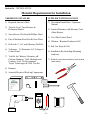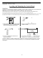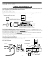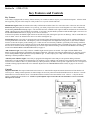
1
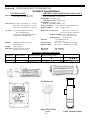
Soft Water Purification System
CUBBY
by AquaCal AutoPilot
INC.
Residential
Operation / Installation Manual
Chlorine
Jerry
Jug
Tablets
/
1
1
1
Clarify Metal 1
Algae
Out Cal
Hypo
IMPORTANT
Read This Manual Before Installing & Operating
18504 REV 8
12-20-2007
Section 1a – GENERAL PRODUCT INFORMATION
POOL PILOT
CUBBY
by AquaCal AutoPilot
INC.
Record Following Information & Provide When Calling Factory:
Installer ________________________________________________________________
Date installed _________________________ Volume of Pool _____________________
Model Number _________________ Control Panel Serial Number _________________
Cell Serial Number _________________
Factory Direct Customer Assistance…
HOTLINE: 800-786-7751 or 727-823-5642
FAX: 866-422-1654
Visit Us On The Internet @
http://www.AutoPilot.com
Manufactured by
AquaCal AutoPilot
TH
2737 24 Street N • St. Petersburg • Florida 33713, U.S.A.
POOL PILOT
CUBBY
by AQUACAL AUTOPILOT
INC.
-1-
Section 1b – GENERAL PRODUCT INFORMATION
IMPORTANT SAFETY INSTRUCTIONS
READ AND FOLLOW ALL INSTRUCTIONS
INSTALLATION AND EQUIPMENT RELATED
Installation of all CUBBY models:
When installing and using your Cubby Control Panel, basic safety precautions must always be followed, including the following:
1.
Follow all aspects of the local and National Electrical Code(s) when installing your Control Panel.
2.
During installation, mount your Control Panel to ensure the least amount of direct exposure to rain, garden sprinkler water, direct
sunlight or any corrosive environment.
3.
WARNING – Risk of electrical shock. Install Control Panel at least 10’ (3 m) for 110V Units, from the inside wall of the pool or spa
using non-metallic plumbing. 5’ minimum distance (1.5 m) for 220V Units.
4.
All field-installed metal components such as rails, ladders, drains or similar hardware within 10’ (3 m) of the spa or hot tub shall be
bonded to the equipment grounding bus with copper conductors not smaller than No. 8 AWG in the U.S.A. and No.6 AWG in
Canada.
5.
CAUTION – Maintain water chemistry in accordance with manufacturer’s instructions.
6.
WARNING – To reduce the risk of injury, do not permit children to use this product unless they are closely supervised at all times.
Children should not use spas, hot tubs or pools without permanent adult supervision.
Equipment Related
110Volt Models Only (cord and plug)
1.
WARNING – Risk of Electrical Shock. Connect only to a grounding type receptacle protected by a ground-fault-interrupter (GFCI).
Contact a qualified electrician if you cannot verify that the receptacle is protected by a GFCI. The conductors on the load side of the
GFCI shall not occupy conduit boxes or enclosures containing other conductors unless additional conductors are also protected by a
GFCI.
2.
WARNING – To reduce the risk of electric shock, replace damaged cords immediately.
3.
WARNING – To reduce the risk of electrical shock, do not use extension cords to connect unit to electric supply; provide a properly
located outlet.
4.
Do not bury cord. Locate and protect cord to minimize abuse from lawn mowers, hedge trimmers and other equipment.
1
A wire connector is provided on your Cubby to connect a minimum No. 8 AWG (8.4 mm²) solid copper bonding conductor between
this unit and any metal equipment, metal enclosures of electrical equipment, metal water pipe or conduit within 5’
(1.5 m) of the unit.
2
A bonding terminal is located inside your Cubby. To reduce the risk of electrical shock, this terminal must be connected to the
grounding means provided in the electrical supply panel with a continuous copper wire equivalent size to the circuit conductors
supplying your Cubby.
3
A disconnection device from the power source, with a contact separation of at least 0.12” (3mm) in all poles, must be incorporated in
the fixed wiring for permanently wired units.
220Volt Models Only (fixed wiring)
SAVE THESE INSTRUCTIONS
-2-
Section 1c – GENERAL PRODUCT INFORMATION
Table of Contents
CUBBY
by AQUACAL AUTOPILOT
INC.
Section 1 GENERAL PRODUCT INFORMATION
1a
1b
1c
1d
Product Information and Contact Numbers ..................................................................1
Important Safety Instructions........................................................................................2
Table of Contents..........................................................................................................3
Technical Specifications ...............................................................................................4
Section 2 INSTALLATION
2a
2b
2c
2d
Material Requirements for Installation .........................................................................5
Locating and Mounting the Control Panel....................................................................6
Control Panel Connections
Electrical/ORP Connections ................................................................................7 - 8
Cell Cord and Output Port Connections ..............................................................8
Locating and Installing the Cell
In-Line Unit .........................................................................................................9
In-Deck Unit with Mixing Canister .....................................................................10
Section 3 OPERATION
3a
3b
3c
3d
3e
Key Features and Controls
Setting the Output Control Dial ...........................................................................11
Understanding System Sizing
Demand Variables for Purifier.............................................................................12
Start-Up Procedures ......................................................................................................13
Pool Water Preparation
Salt Requirement Chart........................................................................................14
Monitoring and Maintenance
Water Chemistry Parameters ...............................................................................15
Manual Cell Cleaning ..........................................................................................15
Section 4 TROUBLESHOOTING AND SERVICING
4a
4b
Troubleshooting ............................................................................................................16
Servicing and Replacing Parts ......................................................................................17 - 18
-3-
Section 1d – GENERAL PRODUCT INFORMATION
Technical Specifications
CONTROL PANEL
Power In:
CHLORINE CELL MODELS 400-3, 400-5, & RC-5
105 – 125 VAC, 50/60 Hz, 75 W
210 – 250 VAC, 50/60 Hz, 75 W
Power Out: RC-5 Cell – 3.0 Amps @ 10 – 16 VDC
400-3 Cell – 3.0 Amps @ 12 – 13 VDC
400-5 Cell – 3.0 Amps @ 10 – 16 VDC
Weight 400-3: 2.0 lbs (0.91 kg)
w/ 25’ (7.6 m) cord: 3.5 lbs (1.6 kg)
Weight 400-5: 2.4 lbs (1.1 kg)
w/ 50’ (15.0 m) cord: 5.1 lbs (2.3 kg)
Weight RC-5 2.4 lbs (1.1 kg)
w/ 12’ (3.7 m) cord: 3.8 lbs (1.7 kg)
Floater w/Canister: 1.5 lbs. (.68 k) w/o Cell (Swan Floater)
In-Deck Chamber: 7.8 lbs. (3.5 kg) w/o Cell
AC Cord:
Dimensions: (In-Line Cell)
3’ (92 cm) grounded cord (110V)
(US / Canadian Units)
2 meter (6.7ft.) grounded cord (220V)
(European / Australian Units)
Housing:
Weatherproof Plastic Cover on
Aluminum Base
Weight:
6 lbs. (2.7 kg)
Dimensions: 11.88”L x 9.38”W x 4.44”D
(30 cm x 24 cm x 11cm)
18.5”L x 2.5” W x 4.1” H
(46.3 cm x 6.25 cm x 10.25 cm)
(In-Deck Chamber) 8”L x 5”W x 20.5” H
(20 cm x 12.5 cm x 51 cm)
(In-Pool Floater)
18” H (45 cm)
Deck Lid:
6.63” Diameter x 2” H
(16.6 cm x 5 cm)
Life Expectancy:
RC-3 Cell: 14,000 hrs @ 3.0 Amps
@100% Output
RC-5 Cell: 14,000 hrs @ 3.0 Amps
ETL Listed:
Approvals:
J99*7396-001
ETL, cETL, CE
Equivalent Production Comparisons
Pool Pilot
Cell Model
3- Blade
Equivalent ounces
Liquid Chlorine
32 oz (1.06 L)
Equivalent Ounces
Granular Tri-Chlor
4.5 oz (125 g)
5- Blade
64 oz (2.13 L)
9.0 oz (257 g)
Equivalent 8 oz. (229g) Tri-Chlor
Tablet Produced per Day
Weekly Production
4 Tablets
8 Tablets
“CUBBY Eliminates the Chlorine Hassle”
Production Cell
Control Panel
Plug-N-Play Floater
(Swan)
-4-
Cubby In-Deck Canister
Section 2a – INSTALLATION
Material Requirements for Installation
NEEDED BY INSTALLER
SUPPLIED WITH POOL PILOT
1) Required Amount of Salt
1) Residential Installation / Operation
Manual
2) Torpedo Level, Tape Measure &
Permanent Marker
2) Limited Warranty with Warranty Card
(Must Return)
3) Screwdrivers: Flat Head & Phillips Head
3) Pool Pilot Control Panel
4) Pair of Medium Sized Needle Nose Pliers
4) Chlorine / Bromine Production Cell
5) Drill with ¼” (6.3 mm) Masonry Drill Bit
5) Salt Test Strips & Vial
6) Voltmeter – To Determine A/C Voltage to
Control Panel
6) Installation Kit; Including Mounting
hardware
7) Test Kit for Chlorine / Bromine, pH,
Calcium Hardness, Total Alkalinity and
Cyanuric Acid. We Recommend
Taylor Technologies K-2005 Test Kit
7) In-deck convection canister (convection
units only).
8) Hammer
9) Assorted Electrical Hook-up Components
Auto
Salt
Plus™
NON-STAINING Salt
STABILIZE YOUR POOL AS YOU CHLORINATE
Specifically blended for chlorine pools and spas
Utilizing any of the following:
• AutoPilot Purification Systems
• Pool Pilot by AutoPilot
• Lectranator
• Kreey Klear
• Chlormatic
• Aqua Rite
• Eco-matic
-5-
Section 2b – INSTALLATION
Locating and Mounting the Control Panel
Control Panel
WARNING: USE THE SUPPLIED ANCHORS AND SCREWS TO MOUNT THE CONTROL PANEL. DO NOT SHOOT OR
PERMANENTLY ATTACH THE CONTROL PANEL TO THE WALL! This will void warranty.
NOTE: Install at least 10’ (3.0 m) for 110V Units or 5’ (1.53 m) for 220V Units from the inside wall of the pool or spa.
The Control Panel should be set on a vertical surface away from excessive exposure to sunlight and moisture.
The standard cord length for the Plug-N-Play Swan Floater cell 400-3 is 25’ (7.6 m) and the Cubby In-Deck cell 400-5 is 50’ (15 m) and
the Cubby In-Line cell RC-5 is 12’ (3.8 m) which will require the Control Panel to be located within these distances respectively.
CUBBY
Output
Control
0%
OFF
Flashing GreenGood
Flashing RedCheck System
100%
MAX
OK
CHECK
SYSTEM
CUBBY
by AQUACAL AUTOPILOT
1) Using a torpedo level and permanent marker, hold the
Control Panel on the surface to be mounted and dot
each of the (4) mounting holes with the marker.
2) Using a 1/4” (6.3 mm) Masonry Drill Bit, drill to
a depth of 1”(26 mm)
Cubby
OUTPUT
CONTROL
3) Insert the (4) supplied plastic wall anchors and
tap flush with a hammer.
0%
100%
4) Your Pool Pilot Control Panel is now ready to receive the (4)
mounting screws to complete the Control Panel Mounting.
CAUTION – REMOVAL OF THE CONTROL PANEL COVER IS NOT NECESSARY FOR INSTALLATION. If removal
becomes necessary, follow the directions for Removing the Housing Cover in the SERVICING AND REPLACING PARTS
section, page 17.
-6-
Section 2c – INSTALLATION
Control Panel Connections
Electrical Connections: In-Line units must be integrated with the Pool Pump Operation and must be connected to
the load side of the pump control system. Convection units must be connected to the line side AC power from a
dedicated circuit breaker, external control switch or any other constant Power Source. For flexibility, ease of
wiring and making connections, #14 gauge stranded wire is recommended for interconnection between the Power
Source and the Control Panel. Wiring diagrams are located on the Control Panel’s Back Plate.
U.S. / Canadian 220 Volt Models Only (You cannot switch to 110 Volt Power)
The 220V Cubby models come supplied with 6’ (1.8 m) of lead wiring to connect to your Power Source. Use the
green and yellow stranded wire for Control Panel grounding. Attach a #8 or #6 solid bond wire to the Ground Lug
on the underside of the unit. Connect the blue and brown wires from the Control Panel to the incoming AC power.
Use the wire supplied nuts if needed.
Ground Lug
BLUE 2-Prong Low Output Port
WHITE 2-Prong Normal Output Port
Knockout
Plug
Cubby Base Plate
To 220V Power Source
Banana Jack Type Cell Ports
Two-Prong Connector
With Supplied 6’ (1.8 m) Lead Wires
(Flow Detector or Output Jumper)
U.S. / Canadian 110 Volt Models Only (You cannot switch to 220Volt Power)
Wiring: The 110V Cubby models come supplied with a 3’ (92 cm) grounded AC cord. Plug into a Ground Fault
Circuit Interrupter (GFCI) Protected Outlet.
Ground Lug
BLUE 2-Prong Low Output Port
WHITE 2-Prong Normal Output Port
Cubby Base Plate
Banana Jack Type Cell Ports
3’ (92 cm) Grounded AC Cord to GFCI Protected Outlet
-7-
Two-Prong Connector
(Flow Detector or Output Jumper)
Section 2c – INSTALLATION
Control Panel Wiring
European 220 Volt / 50 Cycle Models Only
The 220V Cubby models come supplied with 2 m (6.7 ft) European plug. Attach a #8 or #6 solid bond wire to the
Ground Lug on the underside of the unit.
Ground Lug
BLUE 2-Prong Low Output Port
WHITE 2-Prong Normal Output Port
Knockout
Plug
Pool Pilot Base Plate
Banana Jack Type Cell Ports
European 2 m (6.7 ft) 220V Plug to Power Source
Two-Prong Connector
(Flow Detector or Output Jumper)
Flow Detector / Cell Production Output Ports:
The In-Line unit is provided with a Flow Detector and the Convection Unit comes with an Output Jumper that has
a 2-Prong connector. Plug the Flow Detector or Output Jumper connector to the White Port for Normal Purifier
output, or the Blue Port for Low Purifier output (reduced to 12.5% output) for spas, above ground or small volume
pools.
ORP Controller: Follow the directions for Removing the Housing Cover in the SERVICING AND REPLACING
PARTS section, on page 17. The Circuit Board has a 2-pin connector at terminal JP4, that when shorted, the
BLUE Output Port becomes the input for the ORP Controller. Use Special Order PN# 993 to install the shorting
jumper at JP4 and use the supplied cable to the ORP Controller Output. Ensure that your Output Control Dial is
set to 0% AND the flow switch is connected to the White Normal Output Port.
WARNING: This is a dry contact input. DO NOT ENERGIZE THIS INPUT. DAMAGE TO THE CONTROL PANEL WILL
OCCUR AND THE WARRANTY WILL BE VOIDED.
-8-
Section 2d – INSTALLATION
Locating and Installing the Cell
The Location of the Control Panel is not drawn to scale and cannot be mounted closer than 10’ (3.0 m) from the inside wall of the
pool or spa for 110V Units. 5’ (1.5 m) minimum distance for 220V Units.
In-Line Cell Installation Diagram
Pool Pilot In-Line Cell: The In-Line Pool Pilot model uses a flow detector to read a minimal water flow of 15 gallons per minute
(gpm) (3.4 m³/hr). It is also recommended that for water flow greater than 50 gpm (11.3 m³/hr), a 2 lb spring check valve be used to
bypass excess flow. A typical In-Line installation locates the cell and flow detector after all other equipment.
External Filter Pump Control System
CUBBY
Output Control
Required Salt Level
2500 - 3500
LOADSIDE A/C Power From
External Filter Pump Control System
Pool Pilot Control Panel
Flashing Green Light
– Generating Purifier
Flashing Red Light
– Check System
CUBBY
By AUTOPILOT SYSTEMS
Cell and Flow Detector Cords
OUTLET
INLET
PUMP
FILTER
HEATER
OPTIONAL BYPASS 3 LB CHECK VALVE
(For High Flow Conditions Over 50 gpm (11.3 m³/hr))
For Pool/Spa Combination, whether single pump or dual pump configuration, locate the cell in the POOL RETURN line only.
This prevents over saturation of the chlorine residual in the spa when isolated.
For a Single Pump system using Motorized Valve Actuators, if the spa is raised, a swing check valve must be installed after the three way
Return (Motorized) Valve on the Spa Jet Line to ensure spa drain down does not occur.
For a Dual Pump system using hydraulic valves, if the spa is raised, a 5lb spring check valve must be installed on the Pool Return line
before the flow detector to ensure adequate spa spillover.
If you require further assistance, please contact our office for plumbing diagrams or other assistance.
Convection Cell Installation Diagrams
In-Pool Floating Cell: Secure the Cell Cord to the side but allow enough slack so that the Cell is capable of being placed on the deck
for cleaning or maintenance. NOTE: Do not place the Floater adjacent to any
entrance or exit areas.
Spa or Above Ground Pool
In-Ground Pool
Control Panel
Cord Attachment
Point
Control Panel
5’ (1.5 m) Optional
Protective Cord Cover
P/N 17225
CUBBY
Output Control
Required Salt Level
2500 - 3500
Output Control
Flashing Green Light
– Generating Purifier
Flashing Red Light
– Check System
CUBBY
By AUTOPILOT SYSTEMS
Cell Cord
To a 110V GFCI
Power Source
Flashing Green Light
– Generating Purifier
Flashing Red Light
– Check System
CUBBY
By AUTOPILOT SYSTEMS
Cell Cord
CUBBY
To a 110V GFCI
Power Source
-9-
Section 2d – INSTALLATION
Locating and Installing the Cell (Continued)
Convection Cell Installation Diagrams
In-Deck Canister with Cell: Use 1.5” (3.81 cm) minimum diameter pipe from Canister. The discharge (effluent) side of the
Canister is to be at a typical location and should be mounted a minimum of 6” (15.4 cm) below the normal water level. The suction
(influent) side of the Canister can be plumbed to several locations. Contact us for additional schematics with dual port bottom drain or
side suction sump, or skimmer connections.
Two Styrofoam pieces are provided with the In-Deck Canister. Place the smaller Styrofoam plug into the bottom of the canister to protect
against debris clogging the bottom port. The larger Styrofoam ring is used to attach the Deck Ring and Lid. Ensure that the deck lid is
centered and positioned over the canister before paving or pouring the deck, so that there is easy access to the cell for service.
After positioning the canister, it is recommended to pour a concrete shell encasing the canister to prevent any potential breakage. Ensure
that the suction and discharge openings are 1” (2.54 cm) minimum and are unobstructed (*see note below).
The canister is supplied with a 1” conduit fitting. We recommend using 1” conduit from the canister back to the Control Panel to
ease installation/replacement of the cell cord. We also recommend that as few angles as possible are used to route the conduit. To
avoid twisting and kinking the cord, un-bundle the cell cord and lay it flat across the deck before pulling through the conduit. Route and
pull the Cell cord through the conduit to the Control Panel until the Cord Stop Label is at the Conduit Opening (approximately 18” (45.72
cm) from cell) to allow access of the cell from the deck.
NOTE: Before the pool is ready to be filled with water, remove the smaller Styrofoam plug from the bottom of the canister and flush any
debris out with a jet stream of water.
To ensure a quick and easy start up, mix a bucket of water from the pool, previously treated with salt, into the convection canister. This
assures proper salt levels in the canister for cell activation.
This distance will vary depending on the thickness of the wall and coping.
Min: 14” (35.6 cm.)
Position the top of the In-Deck Well, 1” (2.5 cm)
Elevated decks will require using a 4” (10.2 cm)
below the top of the deck. Use the provided
2”(5.1cm) coupling to extend the well to the
transition ring to adjust and hold the Deck Ring
appropriate height.
in place when pouring or setting the deck.
2”(5.1cm)
Position the Deck Ring flush with the deck surface.
When positioned correctly, the
10.5”(26.4 cm) 1”Electrical Conduit raceway will
Ensure that the discharge line is
remain dry, approximately 3”
a minimum of 6” (15.4 cm)
(7.6 cm) above normal water level.
Discharge
below the water line.
Min: 12” (30.5 cm)
Spacing
Max: None, but
Eq. Pad
between
limited to the flat
pipes
surface before the
transition curve between
the wall and floor.
Position the Canister
Position this pipe before the transition
curve from the Wall to the Floor.
Wall Fittings can be used on the pipe
for a finished look
Suction
close to the Cubby Control Box.
Do not extend the suction and discharge
piping further back than 2’ (60 cm).
* CAUTION: Use 1.5” (3.81 cm) minimum diameter
pipe from Canister. Inlet fittings can be used to
provide a finish appearance to the wall. However,
do not use the eyeball inserts or reduce less than
1” opening!
For highest efficiency, it is recommended to position the In-Deck canister with as short a run to the Cubby Control Panel as possible and
to cut back any excess cell cord. Provided enough slack at the control panel, one or two loops of cord, for servicing the cell if needed.
Installation Video is available upon request.
- 10 -
Section 3a – OPERATION
Key Features and Controls
Key Features
Your Cubby is equipped with several key features and very few controls to make it easy for you to maintain and operate. After the initial
start-up period, your pool will be ready for Cubby to take over so you can sit back and relax!
Identification signal: When first turned on the Cubby will flash the red LED 3 times for a convection unit or 5 times for an in-line unit.
Self-Test Cycle: During the first minute of every start-up, your Cubby will perform a series of self-diagnostic test. This is indicated by
the alternating GREEN/RED flashing Lights. After the initial Self-test, a GREEN “OK” Light will indicate all functions are normal while
a RED “Check System” Light will indicate any problem. Your Cubby may halt Purifier production until the RED Light is corrected. See
the TROUBLESHOOTING section, on page 15 for corrective measures.
At the end of operation, the GREEN Light remains on and will slowly dim, allowing the capacitors to discharge. This is normal and not a
cause for alarm. Allow one minute for the unit to reset before starting back up.
Self-Cleaning Cycle: Your Cubby is equipped with a self-cleaning feature that automatically cleans the Cell for optimum efficiency by
reversing the electrical current flow. The frequency of the reversal depends on the Output Dial setting so that as your Purifier demand
increases so does the frequency of the cleaning cycle. Under extreme water chemistry imbalance, specifically scale forming conditions,
or high calcium hardness levels, a build-up can occur on the blades much faster than this feature can handle at the factory settings. When
the reversal rate cannot clean the scaling sufficiently, the Cell will require manual cleaning, as described in the Manual Cell Cleaning
section in the MONITORING AND MAINTENANCE, on page 15.
“OK” Indicator Light: Your Cubby will show a GREEN Light when all systems are normal. The Light will flash GREEN when
Purifier is being generated and is controlled by the Output Control Dial. The higher percentage the Output Dial is set, the more you will
see the flashing GREEN Light rather than a steady GREEN Light. At 100% Output, your Cubby will be constantly flashing GREEN,
indicating a constant production of Purifier.
“Check System” Indicator Light: Your Cubby is equipped with a diagnostic feature that prevents operation during cold water
temperatures, low salt residual levels and improper Cell conditions. These conditions can contribute to the premature deterioration of the
conversion Cell. Whenever there is a problem with any of these parameters, the RED “Check System” Light will come on. The sequence
of flashes will help pinpoint what needs to be cleaned or adjusted. See the TROUBLESHOOTING section, on page 16 for corrective
measures.
Controls
Output Control Dial: The Output Control Dial varies from 0% to 100% Purifier output and controls the amount of time that the Cell
receives power. During normal operation, no control changes are necessary unless the Purifier demand increases or decreases. Turn the
Dial clockwise to increase Purifier levels. Turn the Dial counter-clockwise to decrease Purifier levels. Allow 2 – 3 days for the new
setting to establish the new Purifier level. NOTE: Any interruption of power will cause the current memory cycle to reset itself
when power is restored.
- 11 -
Section 3b – OPERATION
Understanding System Sizing
Cubby Purifier Demands
The rate at which Purifier is consumed in any swimming pool depends on the relationship of several major variables. Since these
variables can vary widely from pool to pool and season to season, precise prediction of the Purifier demand for any one pool can be
difficult.
The Demand Variables are:
1. Volume and Surface Area of the pool / spa being purified:
Determining Volume of Pool
It is important to determine the volume of water that is in your pool for the proper addition of salt and other chemicals.
Use these three formulas to figure your correct gallonage, or cubic meters of water in the pool/spa and
record on Page 1 for future reference:
Rectangular Pool: Length (L) X Width (W) X Average Depth ((D1 + D2) / 2) X 7.5 = Total Gallons
Length (L) X Width (W) X Average Depth ((D1 + D2) / 2) = Total Cubic Meters
D1 (Shallow End)
L
D2 (Deep End)
W
Oval / Round Pool: Diameter (L) X Diameter (W) X Average Depth ((D1+D2) / 2) X 5.9 = Total Gallons
Diameter (L) X Diameter (W) X Average Depth ((D1 + D2) / 2)X 0.79 = Total Cubic Meters
L
D1 (Shallow End)
W
D2 (Deep End)
2. Average Water Temperature Maintained: As the temperature of the water increases, the Purifier demand will also increase. As the
temperature of the water decreases, the Purifier demand will also decrease. When this happens, the Output Dial should be adjusted
to compensate for this change in demand (which will also protect your equipment from excessive levels of Purifier). AquaCal’s
Icebreaker® Heat Pumps allow you to heat in the winter and cool in the summer to maintain a constant water temperature year
around and extending your swimming pool enjoyment.
3. Cyanuric Acid Level Maintained: This chemical, also called stabilizer or conditioner, when added to pool water, significantly
inhibits Purifier depletion from exposure to sunlight. Cyanuric acid also inhibits corrosion if your pool is equipped with any metal
components. Minimum levels or better must be maintained to ensure that the Purifier being produced is protected from UV
breakdown.
4. Bather Load: As the bather load increases, the Purifier demand also increases.
5. Amount of direct sunlight / UV exposure: Pools exposed to larger amounts of direct sunlight are more vulnerable to increased
Purifier loss and algae growth. Indoor or screened pools have less Purifier demand.
6. Exposure to vegetation and airborne debris: Dense landscaping near or around the pool, along with increased nitrate levels (urine,
bird droppings, fertilizer, well water, etc.) greatly contribute to increased Purifier demand. Nitrates and phosphates provide food
for algae to thrive in. Using Lo-chlor Chemical’s Starver treatment removes phosphates from the water to prevent algae growth.
7. Chemical Dilution: Virtually all pool chemicals experience dilution though rainfall, adding of fresh make-up water due to
evaporation, splash-out, filter backwashing, leaks, etc. When freshwater is added for any of the above reasons, Purifier demands
increase for a brief period.
8. (In-Line Only) Main Filter pump run time and your pool’s circulation patterns: Sanitizer can only be produced while the filter
pump is operating. During heavy sanitizer demand conditions such as warm water temperature, heavy swimmer usage or heavy
waterfall/fountain/water feature usage, the filter pump run time may need to be increased to satisfy this high demand.
- 12 -
Section 3c – OPERATION
Start Up Procedures
The following steps should be taken to ensure a proper start-up with the Cubby Purifier. In the event that you need to drain and refill your
pool for any reason, refer to this section for a successful start-up.
NOTE: Do not use your Cubby at start-up after freshly filling pool. First get your water clear, blue and in proper balance before
turning on your Cubby!
1.
After balancing your water chemistry according to the Water Chemistry Parameters section on page, add the proper amount of salt, as
instructed in the Salt Requirement Chart, on page 14 of this manual and circulate 24-hours prior to starting your Cubby. It is
recommended to also add a handful of salt, or mix a bucket of pre-treated salted water directly into the In-Deck Canister to assist
at start-up.
2.
Your Cubby In-line runs in conjunction with your Filter Pump. Your Cubby In-deck runs independent of the filter pump and should
display a GREEN Light when power is sent to the Control Panel.
3.
Turn your Output Control Dial to 50%. Upon start-up, you will see the RED and GREEN Lights flash alternately for a brief period
while the Cubby performs a self-test. After this, the “OK” Light will remain GREEN. If the RED “Check System” Light appears,
it is an indication of a problem.
4.
Whenever the “OK” Light is GREEN, power is being supplied to the control panel. Whenever the “OK” Light is flashing GREEN,
Purifier is being generated. Your Cubby will cycle between steady and flashing GREEN according to the Output Dial Setting,
except at the 100% setting, where your Cubby will be constantly flashing GREEN and producing Purifier. If a RED “Check
System” Light is displayed, there is a problem with part of the system. Please note the sequence of flashes, either single, double,
triple or quadruple, and consult the TROUBLESHOOTING section, on page 16.
5.
For the first two weeks, test the water every 2-3 days for proper Purifier levels. Raise or Lower the Output Control Dial as needed,
according to your test results. A simple rule to follow…
As the water temperature decreases, Purifier demand also decreases.
Lower the Output Dial setting to satisfy this change in Purifier demand until it is necessary to raise the residual level. Water
temperatures below 60°F are detrimental to the life of the Cell. We recommended setting the Output Dial to 0% and manually
“shock” with Potassium Monopersulfate or chlorine, as needed, until the water temperature increases above 60°F.
As the water temperature increases (or an increase in any of the demand criteria), Purifier demand also increases.
Raise the Output Dial setting to satisfy this change in Purifier demand until it is necessary to lower the residual level.
6.
To protect and extend the life cycle of the Cell during a fault condition, a RED warning light will appear, power will be shut off to
the cell, and there will be no “OK” lights lit. At this point, no Purifier is being generated until the RED Light fault condition is
corrected. Check the TROUBLESHOOTING section, on page 16 or contact your dealer or AutoPilot Systems Inc., for further
assistance.
- 13 -
Section 3d – OPERATION
Pool Water Preparation
Salt Requirements
A salt residual of 2500 to 3500 ppm should be maintained at all times for peak efficiency. Allowing less than 2400 ppm salt will activate
a double flashing red “Check System” Light and will reduce the life of the cell. The amount of salt required depends on the size of the
pool and the present salt level.
Type of Salt
It is important to use Sodium Chloride (NaCl) salt that is greater than 99% pure. This is common food salt quality, water softener, or
solar salt and is usually available in 25 lb to 80 lb bags at a local pool or building supply store. Water Softener Pellets can also be used
but will have a slower dissolve rate. Salt with Iodine or anti-caking agents such as YPS (Yellow Prussiate of Soda) should not be used
because they may cause a localized tint to the water or yellow staining on the pool finish. Rock salt should not be used because it
contains high levels of impurities that could cause staining.
How to Add or Remove Salt
On new plaster pools follow the plaster manufacturer’s warranty guidelines to allow the plaster to cure before adding salt. If there is none
then salt can be added immediately. The filter pump should be run with suction coming from the main drain, or the pool cleaner if there is
no main drain. The salt should be added directly to the pool over the main drain and should not be allowed to pile up in one location.
Brush the salt around to speed up the dissolving process. The pump should be run continuously for 24 hours after adding salt. If the salt
level in the pool becomes undesirably high, the only way to reduce it is to partially drain the pool and refill with fresh water.
NOTE: If additional salt is required, Cyanuric acid (stabilizer conditioner) may also be required. Always test cyanuric-acid levels after
adjusting salt levels and add as necessary.
POUNDS (kg) OF SALT NEEDED FOR 3000 PPM RESIDUAL
SALT Level
Pool / Spa Volume in Gallons (m³)
Before Addition 300 (1.1) 500 (1.9) 750 (2.8) 1000 (3.8) 5000 (18.9) 10000 (37.7) 13000 (49.0) 18000 (67.9) 20000 (75.5)
0 ppm 7.4 (3.4) 12.0 (5.5) 19.0 (8.6) 25.0 (11.4) 124.0 (56.4) 248.0 (112.7) 322.0 (146.4) 446.0 (202.7) 495.0 (225.0)
300 ppm 6.7 (3.0) 11.0 (5.0) 17.0 (7.7) 22.0 (10.0) 111.0 (50.5) 223.0 (101.4) 290.0 (131.9) 401.0 (182.3) 446.0 (202.7)
500 ppm 6.2 (2.8) 10.0 (4.5) 15.0 (6.8)
21.0 (9.5) 103.0 (46.8)
206.0 (93.6) 268.0 (121.8) 371.0 (168.6) 413.0 (187.7)
750 ppm 5.6 (2.5)
19.0 (8.6)
93.0 (42.3)
186.0 (84.5) 241.0 (109.6) 334.0 (151.8) 371.0 (168.6)
9.0 (4.1) 14.0 (6.4)
1000 ppm 5.0 (2.3)
8.0 (3.6) 12.0 (5.5)
17.0 7.7)
83.0 (37.7)
165.0 (75.0)
215.0 (97.7) 297.0 (135.0) 330.0 (150.0)
1250 ppm 4.3 (1.9)
7.0 (3.2) 11.0 (5.0)
14.0 (6.4)
72.0 (32.7)
144.0 (65.5)
188.0 (85.5) 260.0 (118.2) 289.0 (131.4)
1500 ppm 3.7 (1.7)
6.0 (2.7)
9.0 (4.1)
12.0 (5.5)
62.0 (28.2)
124.0 (56.4)
2000 ppm 2.5 (1.1)
4.0 (1.8)
6.0 (2.7)
8.0 (3.6)
41.0 (18.6)
83.0 (37.7)
107.0 (48.6)
149.0 (67.7)
165.0 (75.0)
2250 ppm 1.9 (0.9)
3.0 (1.7)
5.0 (2.3)
6.0 (2.7)
31.0 (14.1)
62.0 (28.2)
80.0 (36.4)
111.0 (50.5)
124.0 (56.4)
2500 ppm 1.2 (0.5)
2.0 (0.9)
3.0 (1.7)
4.0 (1.8)
21.0 (9.5)
41.0 (18.6)
54.0 (24.5)
74.0 (33.6)
83.0 ( 37.7)
161.0 (73.2) 223.0 (101.4) 248.0 (112.7)
Note: The above chart is based on 1 lb. (2.2 kg) of salt added to 1 million pounds of water
(Approximately 120,000 gallons (1283 m³)), which equals 1 ppm of salt.
One (1) lb. (2.2 kg) of salt added to 1,000 gallons ( 3.8 m³) will increase your salt residual 120 ppm.
- 14 -
Section 3e – OPERATION
Monitoring and Maintenance
Water Chemistry - VERY IMPORTANT NOTE! Your Cubby is designed to provide Purifier on a daily basis. We recommend the
following water chemistry ranges and periodic checks to monitor your systems efficiency.
Biweekly Checks:
Free Chlorine: 1.0 – 3.0 PPM
Or Bromine: 2.0 – 4.0 PPM
pH:
7.2 – 7.8
Monthly Checks:
Calcium Hardness: 200 – 400 PPM
Salt Residual:
2500 – 3500 PPM
Total Alkalinity:
80 – 120 PPM
Langelier’s Index: ± 0.3 pH of saturation
Cyanuric Acid:
60 – 80 PPM
Visual Cell Inspection for wear, scale or debris
CHLORINE/BROMINE REQUIREMENTS: During Peak Purifier Demand (summer months, rainy season or heavy bather usage) it
may be necessary to increase your Purifier output by increasing your Output Dial setting. Conversely, during Low Purifier Demand, you
can decrease your Output Dial to a lower setting. For extremely Heavy Purifier Demand or to boost your chlorine residual levels quickly,
you can supplement with a shock treatment containing POTASSIUM MONOPERSULFATE or with liquid chlorine.
NOTE: During cold water conditions, below 60ºF, Purifier demand is reduced significantly. For colder climate regions with
sustained low temperatures, visit your local pool professional for proper pool winterizing instructions. For warm climate regions, it is
recommended to reduce your Output Dial setting or introduce a higher chlorine residual (3.0 ppm) then turn “OFF” your Cubby to further
protect the Cell from premature wear.
pH: When your pH falls below the accepted range, your Purifier is used up very quickly. For pH levels higher than the accepted range,
your Purifier becomes much less effective. Improper pH also contributes to the strong smell, red eyes, dry itchy skin and brittle hair
conditions usually associated with “too much Chlorine”.
CALCIUM HARDNESS AND TOTAL ALKALINITY: Your Cubby provides 100% pure Sodium Hypochlorite and does not affect
the calcium hardness or total alkalinity levels. When you start up and maintain your pool with proper water chemistry, it stays balanced
much easier, until influenced by adding other ancillary chemicals or “out of balance” make-up water.
CYANURIC ACID (STABILIZER/CONDITIONER): This chemical goes by either trade name and allows your chlorine residual to
last longer by protecting it from the UV rays of the sun. With low or no Cyanuric acid it is possible for the chlorine being produced, to be
used up just as quickly as it enters the pool.
NOTE: For Bromine or indoor pools, it is not necessary to maintain a stabilizer level to protect the Purifier from the UV rays.
However, it is recommended to maintain a minimal 15-ppm to protect metallic fixtures from possible corrosion.
SALT RESIDUAL: Your Cubby works most efficiently with salt levels between the above-recommended ranges. Low salt will cause
premature deterioration on the Cell blades. For SALTWATER pools, your Cubby is designed to handle up to 35,000 ppm without
harmful effects on the unit. However, high salt levels, above 6000 ppm have been known to cause corrosion on metallic fixtures.
LANGELIER’S INDEX: (or Saturation Index) A mathematical formula used by Pool Professionals to ensure that your total water
chemistry does not fall into a corrosive or aggressive condition. Either condition can cause premature damage to the Cell, any of your
other equipment as well as your cementitious finish.
VISUAL CELL INSPECTION:
REMOVING THE CELL: Follow the directions in the Removing and Replacing the Cell section in the SERVICING AND
REPLACING PARTS, on page 17.
The titanium Cell blades, seen inside the Cell body, should be straight and clear of any debris between the blades. Your Cubby is
designed to automatically self-clean calcium scale build up within the Cell. However, certain conditions can cause a heavier scale build
up that exceeds the self-cleaning capability and would need to be cleaned manually by the method described in the next section.
Manual Cell Cleaning:
With the Cell removed as described in the Removing and Replacing the Cell section in the SERVICING AND REPLACING PARTS, on
page 17, use a high-pressure hose nozzle to spray off as much loose scale and debris as possible. Any remaining calcium scale can be
treated with a mixture of one (1) part Muriatic Acid into four (4) parts water. Mix the solution in a pail, high enough to cover the Cell
blades.
Remove the Cell cord and immerse the Cell so that the blades are completely covered in the solution for no more than 15 minutes
intervals. Drain and flush with fresh water and re-inspect. Repeat the immersion if necessary.
CAUTION: ALWAYS ADD ACID TO WATER, never water to acid.
NEVER USE ANY SHARP OBJECTS TO REMOVE SCALE. Scraping or scratching the titanium blade’s edge or surface will
allow chemical attack of the blade and cause premature failure of the Cell and will void your warranty.
- 15 -
Section 4a – TROUBLSHOOTING AND SERVICING
TROUBLESHOOTING
PROBLEM
1)
CAUSE
SOLUTION
Insufficient Purifier Production
A) The test kit reagents or test strips are old or expired.
B) The unit is set too low in relation to increased demand.
C) The bather load has increased.
A) Retest with new Reagents or Strips.
B) Turn the output dial to a higher setting.
C) Same solution as (B) or add a Non-Chlorine Shock
containing Potassium Monopersulfate, to super-chlorinate.
D) Check your stabilizer level and adjust if needed.
If on Bromine, replenish bromine residual.
E) Repair the leak and rebalance as needed.
F) Check the salt level and adjust as needed. In-Deck wells may
experience low salt at start-up. Manually add a handful into
the In-Deck well to assist start-up.
G) Unplug cable from the BLUE two-hole input and plug into
the WHITE two-hole input.
H) Ensure that this Port is clear from debris.
D) Purifier loss due to intense sunlight exposure.
E) The body of water being purified leaks.
F) Low Salt.
G) Flow Detector / Output Jumper connector plugged
into the wrong input.
H) Suction (bottom port of In-Deck Well) is blocked
2)
Scale Build-up within the Cell.
A) The water being purified contains high pH,
total alkalinity and calcium hardness levels.
B) Possible Cell failure.
C) Power Supply not Reversing.
D) In-Deck Chamber piping restrictive.
3)
A) Calculate Langelier’s Index to assure balanced water. Adjust
chemicals and clean the Cell as described on page 15.
B) Same as above. Replace Cell.
C) Contact the factory for repair or replacement.
D) See Installation Instructions, Pg. 10.
DC Plug and Cell Terminals Burned.
A) The Cell cord plug is not securely pushed onto the Cell
terminals allowing moisture to seep into the plug.
A) Ensure the Cell cord plug is pressed completely onto
the Cell terminal. Check the terminals and clean with
a dry cloth to remove all dirt and corrosion.
B) Contact the factory for Warranty Status and Procedures.
C) Replace the Cell.
B) The Cell terminals leak.
C) Completely failed Cell
4)
Premature Cell Failure (Requires replacement Cell. Life expectancy at 100% Output is approximately 11,000 hrs).
A) Abnormally high Cell usage due to an insufficient
Stabilizer (Cyanuric acid) level.
B) Debris in the Cell.
5)
A) Check the stabilizer level as recommended and adjust.
B) Inspect the Cell monthly and clean debris if needed.
White Flakes in the Water.
A) This occurs when excessive calcium hardness is present
in the water. This should cease after a few days.
A) Visually inspect Cell for scale build-up and clean the Cell as
described on page 15. Adjust water chemistry as needed.
6) No “OK” light with Power to the Control Panel
A) Power fuse blown.
A) Replace this fuse as described on page 17.
7) Single “CHECK SYSTEM” Flash (Purifier Production Output Port).
A) The Flow Detector, Cord or Output Jumper is loose
or not connected properly.
8)
A) Check the Flow Detector, Cord or Jumper for continuity and
tightness into the port and at the Flow Detector.
Double “CHECK SYSTEM” Flashes (Cell Problem).
A) The Cell is scaled.
B) Low salt.
A) See #2 of this section.
B) Check residual salt level of and adjust if needed. It may be
possible for the salt residual in the In-Deck Well to be lower
than the level in the pool. Manually add a handful if needed.
C) Possible Cell failure.
C) See #4 of this section. Contact Factory for repair or replacement.
D) Very cold pool water.
D) Lower the output dial, even to the “0” position and add a
Non-Chlorine Shock containing Potassium Monopersulfate to
the pool until the water temperature increases to above 60°F.
9)
Triple “CHECK SYSTEM” Flashes (Cell Condition, Low Salt or Cold Water Temperatures).
A) No Cell voltage or current.
10)
A) Ensure that the AC supply voltage is correct. If it is correct, send the
Control Panel back to the factory for service.
Quadruple “CHECK SYSTEM” Flashes (Control Panel Problem).
A) Low Cell current - no chlorine.
B) The Cell cord is disconnected from the Cell.
A) Check with a DC current tester. Replace Cell is needed.
B) Ensure that the Cell cord is firmly pressed onto the Cell.
- 16 -
Section 4b – TROUBLSHOOTING AND SERVICING
SERVICING AND REPLACING PARTS
Replacing the Control Panel
Turn off all power going to the Control Panel and verify with a voltmeter. Unplug the Output Jumper and Cell Cords from under the
Control Panel and install in the same location of the new Control Panel. Remove the 220V electrical wire connections from the junction
box, circuit breaker or time clock, or unplug the 110V cord. Page 6 shows the steps to install the control panel. Remove the four Control
Panel mounting screws and replace with the new Control Panel. Reconnect the electrical connections; turn on all power going to the
Control Panel and check for proper operation.
Removing the Housing Cover:
Remove the one-piece knob by prying it off the shaft from its base. This is a compression fit and should pop right off.
Turn off all power going to the Control Panel and verify with a voltmeter. Remove the knob and (6) stainless steel screws and washers,
see below location arrows, and lift off the Housing Cover. Reverse these steps to re-install the cover and knob making sure to align the
Output Control shaft position with the Output Control Dial indicator.
*Align the shaft to 0% or 100% then place the knob with the indictor in the same position.
(6) Screws &
Washers
Locations
Replacing the Power Fuse:
If no Lights are displayed with power going to the Control Panel, inspection and possible replacement of the power fuse may be
necessary. Follow the above directions for Removing the Housing Cover. Once removed, access to the electronics is gained. On the
Control Panel circuit board, there is a power fuse located at terminal FS1. For the 110V unit this is a 2-amp fuse, and a 1-amp fuse for the
220V unit. This fuse protects the Control Panel and Cell from voltage spikes. Remove the old fuse and replace with the new fuse.
Ensure that the fuse rating is the same as the one removed. Re-install the Housing Cover and Output Control Dial knob as described in
the above section.
Control Panel
Circuit Board
FUSE
Fuse Location
Use Fuse Type
2A 250V for 110V systems
1A 250V for 220V systems
ORP
JP4
FS1
L
N
LO FLOW/ORP
- 17 -
FLOW
CELL
Section 4b – TROUBLSHOOTING AND SERVICING
SERVICING AND REPLACING PARTS (Continued)
Accessing the Cell Body
The In-Line Cell Body and Flow Detector are attached with Unions to allow easy access and removal. The In-Deck Cell Body should
be initially installed with enough slack in the cord to allow removing and servicing the cell body on the deck simply by lifting the Cell
Body out. The In-Pool Floating Cell Body should be removed from the Canister housing for manual cleaning. Separate the Top Float
from the Bottom Canister by unscrewing them. Also unscrew the bottom locking fitting (and adapter if supplied) under the Canister to
release the cell body. Remove the Cell body from the Canister.
In-Deck Chamber
Remove Access Lid
Lift the Cell onto the
deck for Servicing
Floating Canister
Cord is placed in the notch of the canister.
ENLARGED CANISTER VIEW
Unscrew top and bottom assemblies.
Notched Cell Cord Location
Turn Counter Clockwise to release.
Turn Clockwise to lock.
Remove bottom locking fitting and adapter.
Removing and Replacing the Cell
In-Deck Unit: Turn the Control Panel off. Ensure that the water level is not above the conduit fitting within the Chamber and drain if
necessary. The Cell cord is permanently wired to the Cell body but is removable at the Control Panel. Unplug the two Banana Plugs and
remove the Banana Plug Housing. Attach a string to the exposed wire ends with enough lead to run the length of the conduit from the
control panel to the Convection Chamber. This will greatly help in pulling the new cord back through the conduit. Pull out the old cord
with the string attached from the Convection Chamber end. The new cord can be tied to the string and pulled back through the conduit to
the Control Panel. Re-attach the wires into the Banana Plug housing and tighten. Insert the Banana Plugs back into the Banana Jacks on
the Control Panel Base Plate
Pull out old
Cell Cord
String
attached
to cord.
To Cell
In-Pool Floating Unit: Turn the Control Panel off. Remove Cell body from the Canister as described above “Accessing the Cell Body”
section. Unplug the two Banana Plugs from the Control Panel and replace the Cell and cord assembly. Reroute the new Cell and cord in
- 18 -
the same location as the original Cell and cord. Re-assemble the Plug-N-Play Cell Body and Canister, and then screw on the Top Float.
Take care to protect the cord wherever exposed to lawn mowers, edgers, hedge trimmers and other equipment.
- 19 -