1
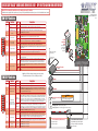
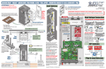
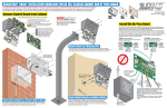
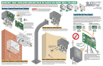
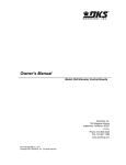
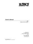
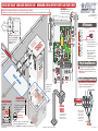
QUICKSTART “BASIC” GUIDELINES FOR MODEL 1601 - WOOD ARM, DOWN LOOP WITH ENTRY LANE TRAFFIC ONLY
Limit Magnets have been pre-set
at the factory to rotate arm 90°.
UP
Magnet
No adjustment is necessary.
Model 1601 is intended for installation only on barrier gates used for vehicles.
Pedestrians must be supplied with a separate access opening. For safety and installation instructions, please refer to the Installation/Owner’s manual.
120 Glasgow Avenue
Inglewood, California 90301
Limit
Vertical
DIP-Switches
Hub
c n
co en t o
nc te pe
re red ra
te o to
pa n r
d.
M
op oun
on po t h
co sit ub
m es o
in id n
g e th
tr o e
M
a f
ou ffic.
C
Arm in the
DOWN Position
Refer to
installation/owner’s
manual for other
type of arms.
REVERSE
SENSITIVITY
DOWN
LOOP
SW2
ON
SW 2
A
1. OFF
2. OFF
3. OFF
4. ON
5. OFF
6. OFF
7. Auto-Close Timer
8. ON
ON
l
Magnetic
Limit
Sensor
1 2 3 4 5 6 7 8
ica
1 2 3 4 5 6 7 8
Ver
t
POWER
SW 1
1 2 3 4 5 6 7 8
rm
1601
A
DOWN
Magnet
Limit
ON
dA
Single Channel
1 2 3 4 5 6 7 8
Ft W
oo
See reverse side.
SW1
UP
LOOP
ON
14
Important: Mount hub as shown
with operator in the DOWN
position. Test hub UP and
DOWN positions before
installing arm.
B
Access Door
Wood bracket
holes.
TIME
DELAY
1. OFF
2. OFF
3. OFF
4. OFF
5. OFF
6. OFF
7. OFF
8. OFF
AS
E
glew
Hz
ffic
a
r
eT
r
Ent
an
yL
Conduit Location
E
10.75”
11”
Mounting Flange
Access Door
Concrete Pad
Existing Wire Restrainers for Running Wires
t
ec
Dir
D
ion
ow
n
L
p
o
o
oo
d,
CA
r
ato
per
o
the ess
tall e acc the
s
n
I th site
o
h
wit r opp .
e
o
n
o
d ic la
ff
a
r
t
NEU
ar
cle arts.
s
e
p
ir
p w ving
Keell mo
a
of
D
Note: Bevel the edges of concrete pad to
eliminate water puddling under the operator.
115 VAC
Convenience
Outlet
23
23”
”
r
h
inc
/4- ith
3
e
Us duit w
n
co eps.
e
sw
we
Po
AC duit
n
Co
rol
ont uit
C
ess ond
Accvice C
De
Tip: Allow concrete to cure completely before attaching operator to pad (48 hours).
UP
Copyright 2013 DoorKing, Inc. All rights reserved.
DOWN
manual and Loop Information Manual (available from
www.dkaccess.com) for more information on loops
and loop detectors.
High Voltage Connection
GATE OPERATOR MUST BE PROPERLY GROUNDED!!
Tip: It is recommended that a surge suppressor be
installed on the high voltage power lines.
Chassis Ground
DANGER
it
ndu
o
pC
Loo
Concrete pad
MUST be level!
OFF
OFF
AC POWER DC POWER
115 VAC
Convenience
Outlet
4” minimum above ground.
This depth of the concrete pad is
determined by soil conditions and
local building codes (reinforced
concrete recommended).
ON
AUTO
E
Concrete Pad
59
C Not included - Refer to the Installation/Owner’s
HOT
ON
Attach the operator
using 1/2” x 3”
sleeve anchors
(Not supplied).
1
When SW1, switch 7 is
turned ON, automatic timer
can be set from 1-59 seconds
to automatically lower arm.
Plug-In Loop Detectors
Neutral
PH
60
, In
To #14 Com
AM
PS
MAX
GA
TE
LO
AD
Do
orKi
ng
, In
c.
1 2 3 4 5 6 7 8 9 10 11 12 13 14
Chassis Ground
To #6 N.O.
CO
NF
AN OR
SI/U MS
L-32TO
CA CE
5
N/ RT
CS IF
A C2 IED
VEH
2.2 TO
ICU
NO
53
. 24
CL
38
LA
2
AS
7
R
S
GAT
EO
MOD
PER
EL
AT
SE
OR
HP
RI
AL
VO
LT
S
Loc
Pla king
te
B
Note: The auto-close timer
CAN be used with a down
loop. Refer to the
installation/owner’s manual
for more information.
NC NO
9410
Auto-Close Timer
115 VAC
Arm Direction
U.S.A.
Access
Control
Device
See reverse side and refer
to Installation/Owner’s
manual for other access
control device connections.
D HIGH VOLTAGE!
Note: “Optional” High
Voltage Kit black and
white wires connect
the same as shown.
See High Voltage Kit
instruction sheet for
more information.
Conduit
115 VAC
1601-366-E-3-13
QUICKSTART “BASIC” GUIDELINES FOR MODEL 1601 - DIP-SWITCH AND WIRING REFERENCE
Model 1601 is intended for installation only on barrier gates used for vehicles.
Pedestrians must be supplied with a separate access opening. For safety and installation instructions, please refer to the Installation/Owner’s manual.
SW 1 DIP-Switches
8
Timer
Up Loop Port Input
ON
Operator uses 180° of gearbox.
OFF
Down / Reverse loop and input will function as a REVERSE loop and REVERSE input.
ON
Normal setting. Down / Reverse loop and input will function as a down input and cause the arm to
rotate down upon deactivation of the input. See SW 1, switch 1 for additional information.
OFF
E
TIM AY
DEL
Normal setting. Operator uses 360° of gearbox. Extends wear life of gearbox.
UP P
LOO
115 VAC
Convenience
Outlets
ON
Relay activates when the UP loop detector (DoorKing plug-in detector only) senses a vehicle presence.
Up Input will raise arm and/or reset the down timer. Input will not lower the arm.
ON
Up Input will raise arm if it is down, or will lower arm if it is up.
OFF
Timer to lower arm is OFF.
ON
Timer to lower arm is ON. Set from 1 to 59 seconds for close time delay. Timer can be used as a
secondary closing command for a down loop. Timer countdown starts when arm has fully raised.
Down loop activation will cancel timer and lower arm OR arm will lower when timer has timed out.
OFF
Output of the loop detector plugged into the UP loop port is switched to terminal 7 for connection to
other input terminals.
ON
Normal setting. Output of the loop detector plugged into the UP loop port will raise arm when
activated.
1601
NC
NO
REVERSE
SENSITIVITY
DOWN
LOOP
Antenna mounted outside
operator housing.
NC NO
Coax Antenna Kit
P/N 1514-073
1 2 3 4 5 6 7 8 9 10 11 12 13 14
3-Wire Radio Receiver
3. 24 Volt
2. Relay
Up-Inputs
Switch
Function
1
Model 1601
Model 1602
OFF
2
Multiple Input Memory
ON/OFF Switch
OFF
Setting
ON
ON
ON
1 2 3 4 5 6 7 8
SW 2
3
4
1. Com
Note: After a DIP-switch setting is changed, power must be turned
OFF and then turned back on for the new setting to take affect.
SW 2 DIP-Switches
Description
Switch must be OFF for model 1601 barrier gate operator.
Switch must be ON for model 1602 barrier gate operator.
Normal setting. Operator will respond to a single UP command, then require a DOWN command.
Operator will not accept multiple Up commands. Operator will not accept the next UP command until
the previous DOWN command is in progress.
5
Reverse Delay
6
7
8
Arm Rotation Direction
OFF
Arm reversal is delayed approximately .5 seconds when a reverse input from terminal 9 is received
during the down cycle. (eg. non-contact sensor beam is blocked). Limited application use.
Normal setting. Instant Reverse – Arm reversal is delayed approximately .1 second when a reverse
input from terminal 9 is received during the down cycle. (eg. non-contact sensor beam is blocked)
Normal setting. Leave in OFF position.
Spare
OFF
Normal setting. Leave in OFF position.
Spare
OFF
Normal setting. Leave in OFF position.
OFF
ON
Down-Inputs
Turns ON the multiple input memory option 1 or 2 (See switch 3). SW 1, switch 4 must also be on.
Override a DOWN command – When the arm is in the up position for a vehicle passing through and the
next vehicle’s UP command is received, the operator will hold the arm up and wait for the next vehicle
Option 1
(OFF Position) to clear the down loop before lowering the arm. The operator will not count multiple UP commands.
Distance between access control device and barrier operator is a factor when using this option. Remote
Multiple Input
transmitters recommended for this option. See Installation/Owner’s manual for more information.
Memory Options
Override Mulitlpe DOWN commands – The operator will count multiple UP commands received during
(SW2, Switch 2 must be ON)
Option 2
an UP command and require a matching number of DOWN commands before lowering the arm.
(SW1, Switch 4 must be ON)
(ON Position) Distance between access control device and barrier operator is a factor when using this option. Remote
transmitters NOT recommended for this option. See Installation/Owner’s manual for more information.
Normal setting. Arm will NOT stop DURING the down cycle.
OFF
Stop Arm Function
Stop Arm Function – Arm will stop DURING the down cycle if a vehicle activates the down loop.
ON
An UP command will raise the arm, or the arm will continue down AFTER the down loop is cleared.
POWER
N
DOWP
LOO
Power safety and
opening devices
that require 115
VAC power.
Normal setting. Relay activates when the DOWN loop detector (DoorKing plug-in detector only) senses
a vehicle presence.
OFF
ER
POW
E
ERSVITY
REVSITI
SEN
Com
7
Up Input Function
Run self-test.
1 2 3 4 5 6 7 8
SW 1
6
Relay 1 Activation
c
oni bly
ctr em
Ele Ass
x
Bo
ON
5
Down / Reverse
Loop and Input
ON
OFF
Normal setting. Self-test is turned off.
1 2 3 4 5 6 7 8
4
Gear Box Travel
OFF
ON
ON
1 2 3 4 5 6 7 8
3
Self-Test
ON
1 2 3 4 5 6 7 8
2
OFF
Description
Activation and then deactivation of the down loop or down / reverse input will cause the arm to rotate
down ONLY if the deactivation occurred after the arm reached the FULL UP position.
Activation and then deactivation of the down loop or down / reverse input will cause the arm to rotate
down AFTER reaching the FULL UP position regardless of when the deactivation occurred.
ON
1
Setting
1 2 3 4 5 6 7 8
Function
Down Active when arm
is full up.
Down Active when arm
is moving up or is up.
U.S.A.
UP
LOOP
ON
Switch
120 Glasgow Avenue
Inglewood, California 90301
TIME
DELAY
Manual Gate Control Toggle
HOLD OPEN
OPEN
P/N 1200-017
WARNING
User MUST make sure gate area IS CLEAR
before manually operating gate arm.
Up toggle position: User toggles switch up to hold gate open.
Center toggle position: Is neutral for normal operation.
Down toggle position: User momentarily toggles switch down to open gate.
Contact Sensor (Reversing Edge)
Non-Contact Sensor (Photo Sensors)
21” Typical Beam Height.
27.5” Max. Beam Height.
Contact and Non-Contact Sensors Note:
Helps minimizes the potential of the arm
lowering on vehicular or other traffic that
loops cannot sense.