1
Digital ANSI-Compliant Printing
Protocol
Level 2 Programming Supplement
Order Number: EK–PPLV2–PS. C01
This document contains device-specific information about level 2 of the
Digital ANSI-Compliant Printing Protocol (DEC PPL2). This protocol is
used by Digital’s advanced character cell printers. For general information
on DEC PPL2, refer to the Digital ANSI-Compliant Printing Protocol Level
2 Programming Reference Manual.
Revision/Update Information:
This is a revised manual.
Operating System and Version: VMS, Version 5.3 or 5.4
Hardware Version:
Digital Equipment Corporation
Maynard, Massachusetts
LA75 Plus Companion Printer, Version 1.0
LA310 MultiPrinter, Version 1.0
LA600 MultiPrinter, Version 1.0
First Printing, October 1991
Revised, November 1992
Revised, July 1994
Digital Equipment Corporation makes no representations that the use of its products in the
manner described in this publication will not infringe on existing or future patent rights, nor do
the descriptions contained in this publication imply the granting of licenses to make, use, or sell
equipment or software in accordance with the description.
Possession, use, or copying of the software described in this publication is authorized only
pursuant to a valid written license from Digital or an authorized sublicensor.
© Digital Equipment Corporation 1991, 1992, 1994. All Rights Reserved.
The postpaid Reader’s Comments forms at the end of this document request your critical
evaluation to assist in preparing future documentation.
The following are trademarks of Digital Equipment Corporation: DEC, LA210, LA310, LA324,
LA424, LA50, LA70, LA75, LA75 Plus, LA600, LN01, LN03, LN03 Plus, and the DIGITAL logo.
ANSI is a registered trademark of the American National Standards Institute, Inc. Epson is a
registered trademark of Seiko Epson Corporation. IBM and Proprinter are registered trademarks
of International Business Machines Corporation. PostScript is a registered trademark of Adobe
Systems, Inc.
S2696
This document was prepared using VAX DOCUMENT Version 2.1.
Contents
Preface . . . . . . . . . . . . . . . . . . . . . . . . . . . . . . . . . . . . . . . . . . . . . . . . . . . . .
xiii
Part I LA75 Plus Companion Printer
1 General Information About the LA75 Plus Companion Printer
1.1
1.2
1.3
1.4
1.5
Description of the LA75 Plus Companion Printer . . . . . . . . .
DEC PPL2 Extensions and Exceptions . . . . . . . . . . . . . . . . .
Alternate Protocols Supported by the LA75 Plus Companion
Printer . . . . . . . . . . . . . . . . . . . . . . . . . . . . . . . . . . . . . . . . . .
Color Printing . . . . . . . . . . . . . . . . . . . . . . . . . . . . . . . . . . . .
Cartridges Supported by the LA75 Plus Companion Printer .
...
...
1–1
1–2
...
...
...
1–3
1–3
1–4
2 Physical Page Characteristics of the LA75 Plus Companion
Printer
2.1
2.2
2.3
2.4
2.5
2.6
2.7
Paper Handling . . . . . . . . . . . . . . . . . . . . . . .
Response to Form Feed (FF) . . . . . . . . . . . . .
Horizontal Text Resolution . . . . . . . . . . . . . . .
Vertical Text Resolution . . . . . . . . . . . . . . . . .
Limits on Partial Line Motion . . . . . . . . . . . .
Tabs . . . . . . . . . . . . . . . . . . . . . . . . . . . . . . . .
Automatic Sheet Feeder Control (DECASFC)
.
.
.
.
.
.
.
.
.
.
.
.
.
.
.
.
.
.
.
.
.
.
.
.
.
.
.
.
.
.
.
.
.
.
.
.
.
.
.
.
.
.
.
.
.
.
.
.
.
.
.
.
.
.
.
.
.
.
.
.
.
.
.
.
.
.
.
.
.
.
.
.
.
.
.
.
.
.
.
.
.
.
.
.
.
.
.
.
.
.
.
.
.
.
.
.
.
.
.
.
.
.
.
.
.
2–1
2–2
2–3
2–4
2–4
2–4
2–4
Initial States . . . . . . . . . . . . . . . . . . . . . . . . . . . . . . . . . . . . . . . .
3–1
3 Initial State Values for the LA75 Plus Companion Printer
3.1
iii
4 Status and Error Reporting for the LA75 Plus Companion
Printer
4.1
4.2
4.3
4.3.1
4.3.2
4.3.3
4.3.4
Device Attributes Report (DAR) . . . . . . . . . .
Secondary Device Attributes Report (DA2R)
Device Status Report (DSR) . . . . . . . . . . . . .
Character Set Not Available . . . . . . . . . .
Downline Load Error . . . . . . . . . . . . . .
Alternate Protocol Error . . . . . . . . . . . .
Initialization Messages . . . . . . . . . . . . .
.
.
.
.
.
.
.
.
.
.
.
.
.
.
.
.
.
.
.
.
.
.
.
.
.
.
.
.
.
.
.
.
.
.
.
.
.
.
.
.
.
.
.
.
.
.
.
.
.
.
.
.
.
.
.
.
.
.
.
.
.
.
.
.
.
.
.
.
.
.
.
.
.
.
.
.
.
.
.
.
.
.
.
.
.
.
.
.
.
.
.
.
.
.
.
.
.
.
.
.
.
.
.
.
.
.
.
.
.
.
.
.
4–1
4–2
4–3
4–4
4–4
4–4
4–4
5 Fonts and Character Attributes on the LA75 Plus Companion
Printer
5.1
5.2
5.3
5.4
5.5
5.6
5.7
5.8
5.9
5.9.1
Built-In Font Repertory . . . . . . . . . . . . . . . . . . . . . . . . . . . .
Additional Character Sets . . . . . . . . . . . . . . . . . . . . . . . . . .
Cartridge Font Repertory . . . . . . . . . . . . . . . . . . . . . . . . . . .
Select Graphic Rendition (SGR) — Cartridge Font Selection
Font Status Report (DECFSR) . . . . . . . . . . . . . . . . . . . . . . .
Density Selection (DECDEN) . . . . . . . . . . . . . . . . . . . . . . . .
Download Font (DECDLD) . . . . . . . . . . . . . . . . . . . . . . . . . .
Slant . . . . . . . . . . . . . . . . . . . . . . . . . . . . . . . . . . . . . . . . . .
Bar Code Printing . . . . . . . . . . . . . . . . . . . . . . . . . . . . . . . .
Select Bar Code Attributes (DECSBCA) . . . . . . . . . . . . .
.
.
.
.
.
.
.
.
.
.
.
.
.
.
.
.
.
.
.
.
.
.
.
.
.
.
.
.
.
.
.
.
.
.
.
.
.
.
.
.
5–1
5–3
5–3
5–5
5–6
5–6
5–6
5–8
5–8
5–8
Graphics Resolution . . . . . . . . . . . . . . . . . . . . . . . . . . . . . . . . . . .
6–1
6 Sixel Graphics Considerations on the LA75 Plus Companion
Printer
6.1
7 Control Characters for the LA75 Plus Companion Printer
7.1
7.2
Bell . . . . . . . . . . . . . . . . . . . . . . . . . . . . . . . . . . . . . . . . . . . . . . .
EOT . . . . . . . . . . . . . . . . . . . . . . . . . . . . . . . . . . . . . . . . . . . . . . .
Part II LA310 MultiPrinter
iv
7–1
7–1
8 General Information About the LA310 MultiPrinter
8.1
8.2
8.3
8.4
Description of the LA310 MultiPrinter . . . . . . . . . . . . . . .
DEC PPL2 Extensions and Exceptions . . . . . . . . . . . . . . .
Alternate Protocols Supported by the LA310 MultiPrinter
Cartridges Supported by the LA310 MultiPrinter . . . . . . .
.
.
.
.
.
.
.
.
.
.
.
.
.
.
.
.
.
.
.
.
8–1
8–2
8–3
8–4
.
.
.
.
.
.
.
.
.
.
.
.
.
.
.
.
.
.
.
.
.
.
.
.
.
.
.
.
.
.
9–1
9–2
9–3
9–3
9–4
9–4
Initial States . . . . . . . . . . . . . . . . . . . . . . . . . . . . . . . . . . . . . . . .
10–1
9 Physical Page Characteristics of the LA310 MultiPrinter
9.1
9.2
9.3
9.4
9.5
9.6
Paper Handling . . . . . . . . . . .
Response to Form Feed (FF) .
Horizontal Text Resolution . . .
Vertical Text Resolution . . . . .
Limits on Partial Line Motion
Tabs . . . . . . . . . . . . . . . . . . . .
.
.
.
.
.
.
.
.
.
.
.
.
.
.
.
.
.
.
.
.
.
.
.
.
.
.
.
.
.
.
.
.
.
.
.
.
.
.
.
.
.
.
.
.
.
.
.
.
.
.
.
.
.
.
.
.
.
.
.
.
.
.
.
.
.
.
.
.
.
.
.
.
.
.
.
.
.
.
.
.
.
.
.
.
.
.
.
.
.
.
.
.
.
.
.
.
.
.
.
.
.
.
.
.
.
.
.
.
.
.
.
.
.
.
.
.
.
.
.
.
.
.
.
.
.
.
.
.
.
.
.
.
10 Initial State Values for the LA310 MultiPrinter
10.1
11 Status and Error Reporting for the LA310 MultiPrinter
11.1
Device Attributes Report (DAR) . . . . . . . . . .
11.2
Secondary Device Attributes Report (DA2R)
11.3
Device Status Report (DSR) . . . . . . . . . . . . .
11.3.1
Character Set Not Available . . . . . . . . . .
11.3.2
Download Font Error . . . . . . . . . . . . . .
11.3.3
Alternate Protocol Error . . . . . . . . . . . .
11.3.4
Initialization Messages . . . . . . . . . . . . .
.
.
.
.
.
.
.
.
.
.
.
.
.
.
.
.
.
.
.
.
.
.
.
.
.
.
.
.
.
.
.
.
.
.
.
.
.
.
.
.
.
.
.
.
.
.
.
.
.
.
.
.
.
.
.
.
.
.
.
.
.
.
.
.
.
.
.
.
.
.
.
.
.
.
.
.
.
.
.
.
.
.
.
.
.
.
.
.
.
.
.
.
.
.
.
.
.
.
.
.
.
.
.
.
.
.
.
.
.
.
.
.
11–1
11–2
11–3
11–4
11–4
11–5
11–5
.
.
.
.
.
.
.
.
.
.
.
.
.
.
.
.
.
.
.
.
.
12–1
12–3
12–3
12–4
12–4
12–5
12–7
12 Fonts and Character Attributes on the LA310 MultiPrinter
12.1
12.2
12.3
12.4
12.5
12.6
12.7
Built-In Font Repertory . . . . . .
Additional Character Sets . . . .
Optional Cartridge . . . . . . . . . .
Select Graphic Rendition (SGR)
Density Selection (DECDEN) . .
Download Font—DECDLD . . . .
Slant . . . . . . . . . . . . . . . . . . . .
......................
......................
......................
— Cartridge Font Selection
......................
......................
......................
.
.
.
.
.
.
.
v
13 Sixel Graphics Considerations on the LA310 MultiPrinter
13.1
Graphics Resolution . . . . . . . . . . . . . . . . . . . . . . . . . . . . . . . . . . .
13–1
14 Control Characters for the LA310 MultiPrinter
14.1
14.2
14.3
Bell . . . . . . . . . . . . . . . . . . . . . . . . . . . . . . . . . . . . . . . . . . . . . . .
EOT . . . . . . . . . . . . . . . . . . . . . . . . . . . . . . . . . . . . . . . . . . . . . . .
ENQ . . . . . . . . . . . . . . . . . . . . . . . . . . . . . . . . . . . . . . . . . . . . . . .
14–1
14–1
14–1
Part III LA600 MultiPrinter
15 General Information About the LA600 MultiPrinter
15.1
15.2
15.3
15.4
15.5
15.6
Description of the LA600 MultiPrinter . . . . . . . . . . . . . . .
DEC PPL2 Extensions and Exceptions . . . . . . . . . . . . . . .
Alternate Protocols Supported by the LA600 MultiPrinter
Additional Interfaces with Additional Protocols . . . . . . . . .
Color Printing Provided by the LA600 MultiPrinter . . . . .
Cartridges Supported by the LA600 MultiPrinter . . . . . . .
.
.
.
.
.
.
.
.
.
.
.
.
.
.
.
.
.
.
.
.
.
.
.
.
.
.
.
.
.
.
15–1
15–2
15–3
15–4
15–4
15–4
.
.
.
.
.
.
.
.
.
.
.
.
.
.
.
.
.
.
.
.
.
.
.
.
.
.
.
.
.
.
.
.
.
.
.
.
.
.
.
.
.
.
.
.
.
.
.
.
16–1
16–2
16–3
16–4
16–4
16–4
16–5
16–6
16–7
16–7
16–8
16–8
16 Physical Page Characteristics of the LA600 MultiPrinter
16.1
16.2
16.3
16.4
16.5
16.6
16.7
16.8
16.9
16.10
16.11
16.12
vi
Paper Handling . . . . . . . . . . . . . . . . . . .
Response to Form Feed (FF) . . . . . . . . .
Automatic Sheet Feeder Control . . . . . .
Paper Tray Selection (DECSITF) . . . . . .
Paper Exit Control (DECPEC) . . . . . . . .
Printhead Gap Control (DECPHGC) . . .
Horizontal Text Resolution . . . . . . . . . . .
Vertical Text Resolution . . . . . . . . . . . . .
Limits on Partial Line Motion . . . . . . . .
Printable Area . . . . . . . . . . . . . . . . . . . .
Logical Page to Physical Sheet Mapping
Tabs . . . . . . . . . . . . . . . . . . . . . . . . . . . .
.
.
.
.
.
.
.
.
.
.
.
.
.
.
.
.
.
.
.
.
.
.
.
.
.
.
.
.
.
.
.
.
.
.
.
.
.
.
.
.
.
.
.
.
.
.
.
.
.
.
.
.
.
.
.
.
.
.
.
.
.
.
.
.
.
.
.
.
.
.
.
.
.
.
.
.
.
.
.
.
.
.
.
.
.
.
.
.
.
.
.
.
.
.
.
.
.
.
.
.
.
.
.
.
.
.
.
.
.
.
.
.
.
.
.
.
.
.
.
.
.
.
.
.
.
.
.
.
.
.
.
.
.
.
.
.
.
.
.
.
.
.
.
.
.
.
.
.
.
.
.
.
.
.
.
.
.
.
.
.
.
.
.
.
.
.
.
.
.
.
.
.
.
.
.
.
.
.
.
.
17 Initial State Values for the LA600 MultiPrinter
17.1
Initial States . . . . . . . . . . . . . . . . . . . . . . . . . . . . . . . . . . . . . . . .
17–1
18 Status and Error Reporting for the LA600 MultiPrinter
18.1
Device Attributes Report (DAR) . . . . . . . . . .
18.2
Secondary Device Attributes Report (DA2R)
18.3
Device Status Report (DSR) . . . . . . . . . . . . .
18.3.1
Character beyond the Right Margin . . . .
18.3.2
Initialization Messages . . . . . . . . . . . . .
.
.
.
.
.
.
.
.
.
.
.
.
.
.
.
.
.
.
.
.
.
.
.
.
.
.
.
.
.
.
.
.
.
.
.
.
.
.
.
.
.
.
.
.
.
.
.
.
.
.
.
.
.
.
.
.
.
.
.
.
.
.
.
.
.
.
.
.
.
.
.
.
.
.
.
.
.
.
.
.
18–1
18–2
18–3
18–5
18–5
19 Fonts and Character Attributes on the LA600 MultiPrinter
19.1
19.2
19.3
19.4
19.5
19.6
19.7
19.8
Built-In Font Repertory . . . . . . . . . . . . . . . . . . . . . . .
Additional Cartridge-based Fonts and Character Sets
Font Selection (SGR) . . . . . . . . . . . . . . . . . . . . . . . . .
Density Selection (DECDEN) . . . . . . . . . . . . . . . . . . .
Attribute Selection . . . . . . . . . . . . . . . . . . . . . . . . . . .
Character Size Selection . . . . . . . . . . . . . . . . . . . . . .
Proportional Spacing Mode (DECPSP) . . . . . . . . . . . .
Printing Control Characters . . . . . . . . . . . . . . . . . . . .
.
.
.
.
.
.
.
.
.
.
.
.
.
.
.
.
.
.
.
.
.
.
.
.
.
.
.
.
.
.
.
.
.
.
.
.
.
.
.
.
.
.
.
.
.
.
.
.
.
.
.
.
.
.
.
.
.
.
.
.
.
.
.
.
.
.
.
.
.
.
.
.
19–1
19–4
19–4
19–5
19–7
19–7
19–15
19–16
.
.
.
.
.
.
.
.
.
.
.
.
.
.
.
.
.
.
.
.
.
.
.
.
.
.
.
.
.
.
.
.
.
.
.
.
.
.
.
.
.
.
.
.
.
.
.
.
.
.
.
.
.
.
.
.
.
.
.
.
.
.
.
.
.
.
.
.
.
.
.
.
.
.
.
.
.
.
.
.
.
.
.
.
.
.
.
.
.
.
.
.
.
.
.
.
.
.
.
.
.
.
.
.
.
.
.
.
.
.
.
.
.
.
.
.
.
.
.
.
.
.
.
.
.
.
.
.
.
.
.
.
.
.
.
.
.
.
.
.
.
.
.
.
.
.
.
.
.
.
.
.
.
.
.
.
.
.
.
.
.
.
20–1
20–2
20–2
20–5
20–6
20–6
20–10
20–13
20–13
20–13
20–13
20–14
20–14
20–14
20–14
20–16
20–18
20–21
20 Bar Code Printing on the LA600 MultiPrinter
20.1
20.2
20.3
20.4
20.5
20.5.1
20.5.2
20.6
20.6.1
20.6.2
20.6.3
20.6.4
20.6.5
20.6.6
20.7
20.7.1
20.7.2
20.7.3
Bar Codes Supported . . . . . . . . . . . . . . . . . . . . . .
Start or Stop Bar Codes (DECBAR) . . . . . . . . . . .
Select Bar Code Attributes (DECSBCA) . . . . . . . .
Active Print Position . . . . . . . . . . . . . . . . . . . . . .
Bar Code Examples . . . . . . . . . . . . . . . . . . . . . . .
Line Printer Emulation . . . . . . . . . . . . . . . . .
DEC PPL2 Emulation . . . . . . . . . . . . . . . . . .
Bar Code Characteristics . . . . . . . . . . . . . . . . . . .
Start and Stop Codes . . . . . . . . . . . . . . . . . . .
Parity and the Center Code . . . . . . . . . . . . . .
Quiet Zone . . . . . . . . . . . . . . . . . . . . . . . . . . .
Intercharacter Gap . . . . . . . . . . . . . . . . . . . . .
Number of Characters in a Bar Code . . . . . . .
Check Digits . . . . . . . . . . . . . . . . . . . . . . . . .
Characteristics of the Supported Bar Code Styles
Code 39 . . . . . . . . . . . . . . . . . . . . . . . . . . . . .
Code 93 . . . . . . . . . . . . . . . . . . . . . . . . . . . . .
Code 128 . . . . . . . . . . . . . . . . . . . . . . . . . . . .
.
.
.
.
.
.
.
.
.
.
.
.
.
.
.
.
.
.
.
.
.
.
.
.
.
.
.
.
.
.
.
.
.
.
.
.
.
.
.
.
.
.
.
.
.
.
.
.
.
.
.
.
.
.
vii
20.7.4
20.7.5
20.7.6
20.7.7
20.7.8
20.7.9
20.7.10
20.7.11
20.7.12
Codabar . . . . . . . .
EAN 8 . . . . . . . . .
EAN 13 . . . . . . . .
Industrial 2 of 5 . .
Interleaved 2 of 5 .
MSI mod 10/10 . . .
POSTNET . . . . . .
UPC A . . . . . . . . .
UPC E . . . . . . . . .
.
.
.
.
.
.
.
.
.
.
.
.
.
.
.
.
.
.
.
.
.
.
.
.
.
.
.
.
.
.
.
.
.
.
.
.
.
.
.
.
.
.
.
.
.
.
.
.
.
.
.
.
.
.
.
.
.
.
.
.
.
.
.
.
.
.
.
.
.
.
.
.
.
.
.
.
.
.
.
.
.
.
.
.
.
.
.
.
.
.
.
.
.
.
.
.
.
.
.
.
.
.
.
.
.
.
.
.
.
.
.
.
.
.
.
.
.
.
.
.
.
.
.
.
.
.
.
.
.
.
.
.
.
.
.
.
.
.
.
.
.
.
.
.
.
.
.
.
.
.
.
.
.
.
.
.
.
.
.
.
.
.
.
.
.
.
.
.
.
.
.
.
.
.
.
.
.
.
.
.
.
.
.
.
.
.
.
.
.
.
.
.
.
.
.
.
.
.
.
.
.
.
.
.
.
.
.
.
.
.
.
.
.
.
.
.
.
.
.
.
.
.
.
.
.
.
.
.
.
.
.
.
.
.
.
.
.
.
.
.
.
.
.
.
.
.
.
.
.
.
.
.
.
.
.
.
.
.
.
.
.
.
.
.
.
.
.
.
.
.
.
.
.
.
.
.
.
.
.
.
.
.
.
.
.
.
.
.
.
.
.
.
.
.
.
.
.
20–24
20–24
20–25
20–26
20–26
20–26
20–26
20–27
20–28
Graphics Resolution . . . . . . . . . . . . . . . . . . . . . . . . . . . . . . . . . . .
21–1
21 Sixel Graphics Considerations on the LA600 MultiPrinter
21.1
22 Control Characters for the LA600 MultiPrinter
22.1
22.2
EOT . . . . . . . . . . . . . . . . . . . . . . . . . . . . . . . . . . . . . . . . . . . . . . .
ENQ . . . . . . . . . . . . . . . . . . . . . . . . . . . . . . . . . . . . . . . . . . . . . . .
22–1
22–1
Part IV Appendixes
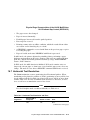
A Printer Communication Interfaces
A.1
A.2
A.2.1
A.2.2
A.3
A.4
Data Communication Interfaces . .
The Serial Port . . . . . . . . . . . . . .
Serial Data Character Format
Serial Data Synchronization .
The Parallel Port . . . . . . . . . . . . .
Automatic Port Selection . . . . . . .
.
.
.
.
.
.
.
.
.
.
.
.
.
.
.
.
.
.
.
.
.
.
.
.
.
.
.
.
.
.
.
.
.
.
.
.
.
.
.
.
.
.
.
.
.
.
.
.
.
.
.
.
.
.
.
.
.
.
.
.
.
.
.
.
.
.
.
.
.
.
.
.
.
.
.
.
.
.
.
.
.
.
.
.
.
.
.
.
.
.
.
.
.
.
.
.
.
.
.
.
.
.
.
.
.
.
.
.
.
.
.
.
.
.
.
.
.
.
.
.
.
.
.
.
.
.
.
.
.
.
.
.
.
.
.
.
.
.
.
.
.
.
.
.
A–1
A–1
A–2
A–2
A–4
A–5
.
.
.
.
.
.
.
.
.
.
.
.
.
.
.
.
.
.
.
.
.
.
.
.
.
.
.
.
.
.
.
.
.
.
.
.
.
.
.
.
.
.
.
.
.
.
.
.
.
.
.
.
.
.
.
.
.
.
.
.
.
.
.
.
.
.
.
.
.
.
.
.
C–2
C–4
C–5
C–6
C–7
C–9
B Comparison of DEC PPL2 Commands by Printer
C DEC PPL2 Command Dictionary Supplement
DECLANS — Load Answerback . . . . . .
DECPSP — Proportional Spacing Mode .
DECPEC — Paper Exit Control . . . . . . .
DECPHGC — Printhead Gap Control . .
DECSITF — Select Input Tray Failover
GSM — Graphic Size Modification . . . . .
viii
.
.
.
.
.
.
.
.
.
.
.
.
.
.
.
.
.
.
.
.
.
.
.
.
.
.
.
.
.
.
.
.
.
.
.
.
.
.
.
.
.
.
Index
Figures
19–1
20–1
20–2
20–3
20–4
20–5
20–6
20–7
20–8
20–9
CRM Output Example . . . . . . . . . . . . . . . . . . . . . . . . . . . .
Extended Code 39 ASCII Character Set . . . . . . . . . . . . . . .
Extended Code 93 ASCII Character Set . . . . . . . . . . . . . . .
Reference Table for Code 93 Check Character Calculation .
Example: Code 93 Characters for ‘‘Code 93’’ . . . . . . . . . . .
Extended Code 128 ASCII Character Set . . . . . . . . . . . . . .
Example: Code 128 Characters for
‘‘0034012345123456789’’ . . . . . . . . . . . . . . . . . . . . . . . . . . .
Example: EAN 13 Characters for ‘‘401234598765’’ . . . . . .
Example: MSI mod 10/10 Characters for ‘‘987654’’ . . . . . .
Example: UPC A Characters for ‘‘01234567890’’ . . . . . . . .
.
.
.
.
.
.
.
.
.
.
.
.
19–16
20–17
20–19
20–20
20–20
20–22
.
.
.
.
.
.
.
.
20–23
20–25
20–27
20–28
DEC PPL2 Extensions . . . . . . . . . . . . . . . . . . .
DEC PPL2 Exceptions . . . . . . . . . . . . . . . . . . .
Horizontal Text Resolution and Fallbacks . . . .
Text Vertical Pitch Fallbacks . . . . . . . . . . . . . .
DECASFC Response . . . . . . . . . . . . . . . . . . . .
Initial State Values . . . . . . . . . . . . . . . . . . . . .
Generic DAR Replies . . . . . . . . . . . . . . . . . . . .
Alias DAR Replies . . . . . . . . . . . . . . . . . . . . . .
DSR Codes . . . . . . . . . . . . . . . . . . . . . . . . . . . .
Initialization Messages . . . . . . . . . . . . . . . . . .
Supported Character Sets . . . . . . . . . . . . . . . .
Available Cartridge Fonts . . . . . . . . . . . . . . . .
SGR Values for Cartridge Font Selection . . . . .
DECDEN Ps Selection . . . . . . . . . . . . . . . . . . .
DECDLD Recommended Parameters Matrix .
DECDLD Acceptable Parameters Matrix . . . .
Bar Code Attributes . . . . . . . . . . . . . . . . . . . . .
Allowed Combinations of Pn Values and Pitch .
Graphics Pitch Fallbacks . . . . . . . . . . . . . . . . .
.
.
.
.
.
.
.
.
.
.
.
.
.
.
.
.
.
.
.
.
.
.
.
.
.
.
.
.
.
.
.
.
.
.
.
.
.
.
1–2
1–3
2–3
2–4
2–5
3–1
4–2
4–2
4–3
4–4
5–2
5–4
5–5
5–6
5–7
5–7
5–8
5–9
6–1
Tables
1–1
1–2
2–1
2–2
2–3
3–1
4–1
4–2
4–3
4–4
5–1
5–2
5–3
5–4
5–5
5–6
5–7
5–8
6–1
.
.
.
.
.
.
.
.
.
.
.
.
.
.
.
.
.
.
.
.
.
.
.
.
.
.
.
.
.
.
.
.
.
.
.
.
.
.
.
.
.
.
.
.
.
.
.
.
.
.
.
.
.
.
.
.
.
.
.
.
.
.
.
.
.
.
.
.
.
.
.
.
.
.
.
.
.
.
.
.
.
.
.
.
.
.
.
.
.
.
.
.
.
.
.
.
.
.
.
.
.
.
.
.
.
.
.
.
.
.
.
.
.
.
.
.
.
.
.
.
.
.
.
.
.
.
.
.
.
.
.
.
.
.
.
.
.
.
.
.
.
.
.
.
.
.
.
.
.
.
.
.
.
.
.
.
.
.
.
.
.
.
.
.
.
.
.
.
.
.
.
ix
6–2
8–1
8–2
8–3
9–1
9–2
10–1
11–1
11–2
11–3
11–4
11–5
12–1
12–2
12–3
12–4
12–5
12–6
12–7
13–1
13–2
15–1
15–2
15–3
16–1
16–2
16–3
16–4
16–5
17–1
18–1
18–2
18–3
18–4
18–5
19–1
19–2
x
Graphics Grid Size Fallbacks . . . . . . . . . . . . . . . . .
DEC PPL2 Extensions . . . . . . . . . . . . . . . . . . . . . .
DEC PPL2 Exceptions . . . . . . . . . . . . . . . . . . . . . .
SOCS/ROCS Commands for Each Emulation Mode
Horizontal Text Resolution and Error . . . . . . . . . .
Text Vertical Pitch Fallbacks . . . . . . . . . . . . . . . . .
Initial State Values for LA310 . . . . . . . . . . . . . . . .
Generic DAR Replies . . . . . . . . . . . . . . . . . . . . . . .
Alias DAR Replies . . . . . . . . . . . . . . . . . . . . . . . . .
DA2R Response Parameters for LA310 . . . . . . . . .
DSR Codes . . . . . . . . . . . . . . . . . . . . . . . . . . . . . . .
Initialization Messages . . . . . . . . . . . . . . . . . . . . .
Supported Character Sets . . . . . . . . . . . . . . . . . . .
Available Optional Cartridge . . . . . . . . . . . . . . . . .
DECDEN Parameters for LA310 . . . . . . . . . . . . . .
DECDLD Font Set Sizes (Pss) . . . . . . . . . . . . . . .
DECDLD Matrix Width (Pcmw) . . . . . . . . . . . . . . .
DECDLD Matrix Heights (Pcmh) . . . . . . . . . . . . .
DECDLD Erase Control (Pe) . . . . . . . . . . . . . . . . .
Graphics Pitch Fallbacks . . . . . . . . . . . . . . . . . . . .
Graphics Grid Size Fallbacks . . . . . . . . . . . . . . . . .
DEC PPL2 Extensions . . . . . . . . . . . . . . . . . . . . . .
DEC PPL2 Exceptions . . . . . . . . . . . . . . . . . . . . . .
SOCS/ROCS Commands for Each Emulation Mode
Ps Parameters for DECASFC . . . . . . . . . . . . . . . . .
Ps Parameters for DECPEC . . . . . . . . . . . . . . . . . .
Ps Parameters for DECPHGC . . . . . . . . . . . . . . . .
Horizontal Text Resolution and Error . . . . . . . . . .
Text Vertical Pitch Fallbacks . . . . . . . . . . . . . . . . .
Initial State Values for LA600 . . . . . . . . . . . . . . . .
Generic DAR Replies . . . . . . . . . . . . . . . . . . . . . . .
Alias DAR Replies . . . . . . . . . . . . . . . . . . . . . . . . .
DA2R Response Parameters for LA600 . . . . . . . . .
DSR Codes . . . . . . . . . . . . . . . . . . . . . . . . . . . . . . .
Initialization Messages . . . . . . . . . . . . . . . . . . . . .
Supported Character Sets . . . . . . . . . . . . . . . . . . .
SGR Parameters for Font Selection . . . . . . . . . . . .
.
.
.
.
.
.
.
.
.
.
.
.
.
.
.
.
.
.
.
.
.
.
.
.
.
.
.
.
.
.
.
.
.
.
.
.
.
.
.
.
.
.
.
.
.
.
.
.
.
.
.
.
.
.
.
.
.
.
.
.
.
.
.
.
.
.
.
.
.
.
.
.
.
.
.
.
.
.
.
.
.
.
.
.
.
.
.
.
.
.
.
.
.
.
.
.
.
.
.
.
.
.
.
.
.
.
.
.
.
.
.
.
.
.
.
.
.
.
.
.
.
.
.
.
.
.
.
.
.
.
.
.
.
.
.
.
.
.
.
.
.
.
.
.
.
.
.
.
.
.
.
.
.
.
.
.
.
.
.
.
.
.
.
.
.
.
.
.
.
.
.
.
.
.
.
.
.
.
.
.
.
.
.
.
.
.
.
.
.
.
.
.
.
.
.
.
.
.
.
.
.
.
.
.
.
.
.
.
.
.
.
.
.
.
.
.
.
.
.
.
.
.
.
.
.
.
.
.
.
.
.
.
.
.
.
.
.
.
.
.
.
.
.
.
.
.
.
.
.
.
.
.
.
.
.
.
.
.
.
.
.
.
.
.
.
.
.
.
.
.
.
.
.
.
.
.
.
.
.
.
.
.
.
.
.
.
.
.
.
.
.
.
.
.
.
.
6–3
8–2
8–3
8–3
9–3
9–4
10–1
11–2
11–2
11–3
11–4
11–5
12–2
12–4
12–5
12–5
12–6
12–6
12–7
13–1
13–2
15–2
15–2
15–3
16–3
16–4
16–4
16–5
16–7
17–1
18–2
18–2
18–3
18–4
18–5
19–2
19–4
19–3
19–4
19–5
19–6
20–1
20–2
20–3
21–1
21–2
A–1
B–1
B–2
B–3
B–4
DECDEN Parameters for LA600 . . . . . . . . . . . . . . . . .
Typestyles and Print Densities . . . . . . . . . . . . . . . . . . .
Graphic Size Modification Parameters . . . . . . . . . . . . .
Data Block Proportional Character Width . . . . . . . . . .
Bar Code Attributes . . . . . . . . . . . . . . . . . . . . . . . . . . .
Supported Values for the Widths of Wide and Narrow
Bars . . . . . . . . . . . . . . . . . . . . . . . . . . . . . . . . . . . . . . .
Bar Code Styles: Characteristics Summary . . . . . . . . .
Graphics Pitch Fallbacks . . . . . . . . . . . . . . . . . . . . . . .
Graphics Grid Size Fallbacks . . . . . . . . . . . . . . . . . . . .
Input Buffer Values . . . . . . . . . . . . . . . . . . . . . . . . . . .
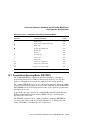
Comparison of DEC PPL2 Commands . . . . . . . . . . . . .
Comparing Extensions to the DEC PPL2 Protocol . . . .
Comparing Exceptions to the Protocol . . . . . . . . . . . . .
Alternative Protocols . . . . . . . . . . . . . . . . . . . . . . . . . .
.
.
.
.
.
.
.
.
.
.
.
.
.
.
.
.
.
.
.
.
.
.
.
.
.
19–5
19–6
19–8
19–8
20–3
.
.
.
.
.
.
.
.
.
.
.
.
.
.
.
.
.
.
.
.
.
.
.
.
.
.
.
.
.
.
.
.
.
.
.
.
.
.
.
.
.
.
.
.
.
20–4
20–14
21–1
21–2
A–3
B–2
B–11
B–16
B–17
xi
Preface
The Level 2 Programming Supplement contains supplemental information
about Digital’s ANSI-Compliant Printing Protocol level 2 (DEC PPL2). This
manual contains information that is specific to the Digital printers that
implement this protocol. It is assumed that the reader has the Digital ANSICompliant Printing Protocol Level 2 Programming Reference Manual, which
provides general information about DEC PPL2.
Purpose of this Manual
This manual provides device-specific information for Digital ANSI-Compliant
Printing Protocol level 2 (DEC PPL2) on the LA75 Plus Companion Printer,
the LA310 MultiPrinter, and the LA600 MultiPrinter.
Intended Audience for this Manual
The Level 2 Programming Supplement is for programmers interested in:
•
Creating applications for specific Digital ANSI-Compliant Printing Protocol
level 2 printers.
•
Understanding how and why documents may appear different if printed on
different Digital printers.
Organization of this Manual
This manual is divided into four parts:
•
Part 1 contains device-specific information about the implementation of
DEC PPL2 for the LA75 Plus Companion printer.
•
Part 2 contains device-specific information about the implementation of
DEC PPL2 for the LA310 MultiPrinter.
•
Part 3 contains device-specific information about the implementation of
DEC PPL2 for the LA600 MultiPrinter.
xiii
•
Part 4 contains appendixes of reference information.
Conventions Used In This Manual
The term DEC PPL2 is used throughout the manual to indicate the Digital
ANSI-Compliant Printing Protocol level 2. The following conventions are used
throughout this manual:
Convention
Meaning
UPPERCASE
Symbols for Digital ANSI-Compliant Printing Protocol level 2
commands are printed in text in uppercase.
Italics
Indicates variables in Digital ANSI-Compliant Printing Protocol level 2
commands.
monospaced
type
Illustrates a Digital ANSI-Compliant Printing Protocol level 2
command. Below each character is a column/row number that indicates
the coded character’s position in a standard code table. For example:
CSI 2
!
v
9/11 3/2 2/1 7/6
xiv
DEC PPL2
Digital ANSI-Compliant Printing Protocol level 2
Command
Dictionary
Refers to Chapter 7 in the Digital ANSI-Compliant Printing Protocol
Level 2 Programming Reference Manual
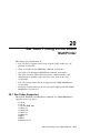
Part I
LA75 Plus Companion Printer
Part I of the Digital ANSI-Compliant Printing Protocol Level 2 Programming
Supplement describes the DEC PPL2 protocol as implemented by the LA75
Plus Companion Printer.
•
Chapter 1 describes the basic features and characteristics of the LA75 Plus
Companion Printer.
•
Chapter 2 describes the printing of the physical page on the LA75 Plus
Companion Printer.
•
Chapter 3 describes the initial state of the printer.
•
Chapter 4 describes how status and error messages are handled.
•
Chapter 5 describes the fonts and font cartridges available on the LA75
Plus Companion Printer.
•
Chapter 6 describes the sixel graphics considerations for the LA75 Plus
Companion Printer.
•
Chapter 7 describes the control characters and their functions on the LA75
Plus Companion Printer.
1
General Information About the LA75 Plus
Companion Printer
This chapter contains the following information about the LA75 Plus
Companion Printer:
•
Description of the LA75 Plus Companion Printer, Section 1.1
•
Protocol extensions and exceptions, Section 1.2
•
Alternate protocols for this printer, Section 1.3
•
Color printing, Section 1.4
•
Cartridges, Section 1.5
1.1 Description of the LA75 Plus Companion Printer
The LA75 Plus Companion Printer is a narrow-carriage, impact dot-matrix
printer. Designed for personal desktop printing, it is also suitable for general
business applications. It has flexible paper handling, and it is capable of
printing on continuous pinfeed paper, single sheets, multiple-part forms,
and envelopes. An Automatic Sheet Feeder (LA75Y-SF) is available, as an
option, to hold and automatically load up to 80 sheets of cut paper. The print
quality is suitable for limited word processing in a small-to-medium computer
environment.
The LA75 Plus Companion Printer:
•
Is a 24-pin printer.
•
Can print in six colors, in addition to black, once the color ribbon (PN
LA75R-KC) is installed.
•
Has a Document on Demand capability (automatic or manual), which
prevents wasting forms or paper between printing jobs.
•
Has an Automatic Viewing capability, which allows the user to see the last
printed line after a job has finished.
General Information About the LA75 Plus Companion Printer 1–1
General Information About the LA75 Plus Companion Printer
1.1 Description of the LA75 Plus Companion Printer
•
Can be connected simultaneously to serial and parallel ports, and switches
automatically between them when data is received.
•
Is compatible with the IBM Proprinter X24E, which is the default protocol
at power-up when the parallel port is used.
Refer to the LA75 Plus Companion Printer Installation and User Guide for
information about installing and using the LA75 Plus Companion Printer.
1.2 DEC PPL2 Extensions and Exceptions
Note
References are made in this manual to Chapter 7 (Command
Dictionary) of the associated manual Digital ANSI-Compliant Printing
Protocol Level 2 Programming Reference Manual. For brevity, that
chapter is called ‘‘Command Dictionary.’’
The implementation of DEC PPL2 on the LA75 Plus Companion Printer
involves a number of extensions and exceptions, which are summarized in
Table 1–1 and Table 1–2. For further information, see Table 18–1, and also
refer to the Command Dictionary.
Table 1–1 DEC PPL2 Extensions
Extensions
Sixel graphics
Sheet feeder
Hebrew character sets
Katakana character set
Greek character sets
Turkish character sets
Color
Metric line spacing
Download Font (DECDLD)
1–2 General Information About the LA75 Plus Companion Printer
General Information About the LA75 Plus Companion Printer
1.2 DEC PPL2 Extensions and Exceptions
Table 1–2 DEC PPL2 Exceptions
Exceptions
Bell
LA210, LA120, LA50 alias Device Attributes Report (DAR) parameters
Control Representation Mode (CRM)
Protocol switching
Horizontal Page Width Alignment (DECHPWA)
Bar code printing (DECSBA, DECBAR)
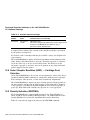
1.3 Alternate Protocols Supported by the LA75 Plus
Companion Printer
This part of the manual describes the DEC PPL2 protocol as implemented on
the LA75 Plus Companion Printer. The LA75 Plus Companion Printer also
emulates the protocol for printing on the IBM Proprinter X24E. The protocol
is changed using either the Select Other Coding System (SOCS)/Return from
Other Coding System (ROCS) command combination, or the Select IBM
Proprinter Mode (DECIPEM) command. These commands are described in the
Command Dictionary.
1.4 Color Printing
For color printing the LA75 Plus Companion Printer uses a ribbon with four
colors. The four ribbon colors can be selected individually and in combinations,
making it possible to print up to eight different colors:
Yellow — (ribbon color)
Magenta — (ribbon color)
Cyan — (ribbon color)
Black — (ribbon color)
Red — (magenta and yellow)
Green — (yellow and cyan)
Blue — (magenta and cyan)
White — (no printing)
The LA75 Plus Companion Printer supports the Select Graphic Rendition
(SGR) color text parameters listed in the Command Dictionary.
In Sixel Graphics mode, the LA75 Plus Companion Printer prints black and
white or color sixels, using the 8-color columns from the HLS and RGB color
maps in the Sixel Graphics chapter of the Reference Manual.
General Information About the LA75 Plus Companion Printer 1–3
General Information About the LA75 Plus Companion Printer
1.5 Cartridges Supported by the LA75 Plus Companion Printer
1.5 Cartridges Supported by the LA75 Plus Companion
Printer
The LA75 Plus Companion Printer supports optional font cartridges. To insert
the cartridge, turn the printer power off, insert the cartridge, and turn the
power back on. If you insert the cartridge while the printer is powered on, the
printer may not be able to select and use the cartridge.
Cartridges contain alternate character sets or typestyles. Select ‘‘print setup’’
while in setup mode to print full details of the contents of the installed
cartridge. See Chapter 5, Fonts and Character Attributes on the LA75 Plus
Companion Printer, for further information.
1–4 General Information About the LA75 Plus Companion Printer
2
Physical Page Characteristics of the LA75
Plus Companion Printer
This chapter explains how the LA75 Plus Companion Printer handles the
transfer of the logical page in memory to the physical paper. Topics include:
•
Paper handling, Section 2.1
•
Response to a Form Feed request, Section 2.2
•
Horizontal text resolution, Section 2.3
•
Vertical text resolution, Section 2.4
•
Limits on partial line motion, Section 2.5
•
Tab support, Section 2.6
•
Automatic sheet feeder control, Section 2.7
In this chapter the top of form paper position is defined as the position of line
1 on the page. This position does not change with the top margin setting.
The form length is defined by the setup feature or by the Set Lines Per Page
(DECSLPP) command.
2.1 Paper Handling
This section summarizes the paper feed modes and loading processes for the
LA75 Plus Companion Printer.
Fanfold Paper — Rear Feed/Top or Rear Output (Push Tractor Mode)
Paper is considered autoloaded when the printer loads it automatically at
power-up or when the user presses the Form Feed (FF) button.
Paper is considered manually loaded when the user inserts it using the platen
knob.
The LA75 Plus Companion Printer can detect the top of the first form only.
Physical Page Characteristics of the LA75 Plus Companion Printer 2–1
Physical Page Characteristics of the LA75 Plus Companion Printer
2.1 Paper Handling
The LA75 Plus Companion Printer uses the form length, as determined by the
setup feature or by the Set Lines Per Page (DECSLPP) command, to compute
the tops of forms other than the first.
Fanfold Paper — Bottom Feed/Rear Output (Pull Tractor Mode)
In this mode there is no autoload function, so the printer cannot detect the top
of form.
The power-up paper position is assumed to be the top of form.
Cut Sheet Paper — Manual Feed/Top Insertion and Top Output (Friction
Mode)
Paper is considered autoloaded when the printer loads it automatically at
power-up or when the user presses the Form Feed (FF) button.
Paper is considered manually loaded when the user inserts it using the platen
knob.
Automatic Sheet Feeder (Friction Mode)
When the sheet feeder is installed and selected there is no manual load
function.
Sheets are automatically loaded when the user presses the Form Feed (FF)
button or when characters are received to be printed.
Manual Feed Mode with Sheet Feeder Installed
The sheet feeder can be deselected by the DECASFC command.
When the sheet feeder is deselected, paper can be inserted manually.
In this mode, the printer works as in Cut sheet paper/Manual feed, except that
the backward motion features (Parking and Viewing) are disabled.
To reactivate Automatic Sheet Feed mode, the DECASFC command must be
used. Alternatively, the sheet feeder can be reselected by turning the printer
power off, then on again.
2.2 Response to Form Feed (FF)
The following information refers to paper motion when the Form Feed (FF)
control code is received; actions that occur when the user presses the Form
Feed (FF) button are not covered.
Fanfold Paper — Rear Feed
When paper is autoloaded, Form Feed (FF) advances the paper to the next top
of form.
2–2 Physical Page Characteristics of the LA75 Plus Companion Printer
Physical Page Characteristics of the LA75 Plus Companion Printer
2.2 Response to Form Feed (FF)
Fanfold Paper — Bottom Feed
The LA75 Plus Companion Printer assumes that the paper position prior to
any paper motion is the reference for the first top of form. Form Feed (FF)
advances the paper to the next top of form.
Cut Sheet Paper — Manual Feed
If paper is not currently loaded, Form Feed (FF) is stored and does not load
paper. If paper is currently loaded, Form Feed (FF) ejects the current sheet if
the physical paper length is equal to, or shorter than, the logical paper length,
as defined during setup or by DECSLPP. If the physical paper length is larger
that the logical paper length, Form Feed (FF) advances paper to the next top
of form.
Automatic Sheet Feeder
When the sheet feeder is installed and paper is currently loaded, Form Feed
(FF) ejects the current sheet. If no paper is currently loaded, Form Feed (FF)
inserts a sheet to top of form. When the sheet feeder is not selected (deselected
by DECASFC), Form Feed (FF) is treated the same as in Cut sheet paper,
Manual feed.
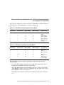
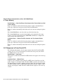
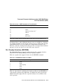
2.3 Horizontal Text Resolution
The LA75 Plus Companion Printer uses approximations for some of the pitches
listed under Set Horizontal Pitch (DECSHORP) in the Command Dictionary.
These approximations, or fallbacks for text resolution, are given in Table 2–1.
All other pitches, as listed in the Command Dictionary, are printed exactly by
the LA75 Plus Companion Printer without fallbacks.
Note
For Sixel Graphics mode resolution fallbacks, see Table 6–1.
Table 2–1 Horizontal Text Resolution and Fallbacks
Target Pitch
Actual
1/2880 inch
Fallback Pitch
6.6
436
6.605
8.25
348
8.2759
13.2
218
13.21
16.5
174
16.55
10.3
288
10
Physical Page Characteristics of the LA75 Plus Companion Printer 2–3
Physical Page Characteristics of the LA75 Plus Companion Printer
2.4 Vertical Text Resolution
2.4 Vertical Text Resolution
The LA75 Plus Companion Printer supports the metric line spacing parameters
under Set Vertical Pitch (DECVERP) in the Command Dictionary.
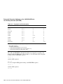
The LA75 Plus Companion Printer uses approximations for the metric line
spacing parameters. These approximations are given in Table 2–2.
Table 2–2 Text Vertical Pitch Fallbacks
Target Pitch
Actual
1/720 inch
Fallback Pitch
1 line/cm
(2.54 line/in)
283
1.002 line/cm
2.544 line/in
2 line/cm
(5.08 line/in)
142
1.996 line/cm
5.070 line/in
4 line/cm
(10.16 line/in)
71
3.992 line/cm
10.141 line/in
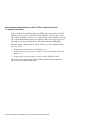
2.5 Limits on Partial Line Motion
When the automatic sheet feeder is installed, the LA75 Plus Companion
Printer limits the PLU count to 12, or 1 inch. This is due to vertical backup
limitations.
In bottom feed mode, the LA75 Plus Companion Printer ignores PLU and PLD
sequences due to mechanical limitations.
In all feed modes, the LA75 Plus Companion Printer ignores PLU and PLD
sequences when within 1.3 inches (3.3 cm) from the bottom of the paper.
2.6 Tabs
The LA75 Plus Companion Printer supports a maximum of 144 horizontal tabs
and a maximum of 252 vertical tabs.
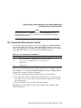
2.7 Automatic Sheet Feeder Control (DECASFC)
The automatic sheet feeder supported by the LA75 Plus Companion Printer
has only one tray. This causes the DECASFC sequence to perform a conditional
Sheet Feed.
If the sheet feeder is not installed, the printer performs a conditional Sheet
Feed on receipt of DECASFC.
2–4 Physical Page Characteristics of the LA75 Plus Companion Printer
Physical Page Characteristics of the LA75 Plus Companion Printer
2.7 Automatic Sheet Feeder Control (DECASFC)
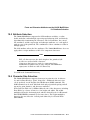
The sheet feeder is selected automatically if it is installed at the time of
power-up. The actions taken by the LA75 Plus Companion Printer in response
to the DECASFC sequence are given in Table 2–3.
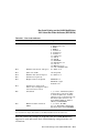
Table 2–3 DECASFC Response
Ps
Action
0 to 98
Performs a conditional Sheet Feed and selects the sheet feeder if not
already selected.
99
Performs a conditional Sheet Feed and deselects the sheet feeder,
then enters manual feed mode.
When the sheet feeder option is installed, but is deselected by sending
DECASFC with Ps = 99, you can insert a single sheet manually in the
appropriate slot on the sheet feeder and load it by pressing the Form Feed (FF)
button.
Physical Page Characteristics of the LA75 Plus Companion Printer 2–5
3
Initial State Values for the LA75 Plus
Companion Printer
This chapter lists the values used by the LA75 Plus Companion Printer for:
•
A power-up reset or a recall of factory default values
•
The Select Conformance Level (DECSCL) command
•
The Soft Terminal Reset (DECSTR) or Reset to Initial State (RIS)
commands
3.1 Initial States
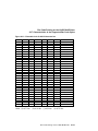
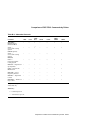
Table 3–1 lists the initial state values used by the LA75 Plus Companion
Printer. The printer always powers up in Ready mode if no error is detected.
Table 3–1 Initial State Values
Recall
Factory
Defaults
(Setup)
Variable or
Control Function
DECSCL
Power-Up
DECSTR
RIS
Protocol
Unchanged
NVM3
Unchanged
Port
dependent
Origin (DECHPWA)
Unchanged
0
Unchanged
0
Vertical pitch
6 line/in
NVM
NVM
6 line/in
Horizontal pitch
10 char/in
NVM
NVM
10 char/in
Active position
Origin
Origin
Origin
Origin4
3 NVM
indicates that the initial state value is stored in nonvolatile memory.
4 Device
performs conditional Form Feed on exit from setup.
(continued on next page)
Initial State Values for the LA75 Plus Companion Printer 3–1
Initial State Values for the LA75 Plus Companion Printer
3.1 Initial States
Table 3–1 (Cont.) Initial State Values
Variable or
Control Function
DECSCL
Power-Up
DECSTR
RIS
Recall
Factory
Defaults
(Setup)
Horizontal Tabs1
Every eight
Every eight
Every eight
Every eight
Line Feed/New Line
Reset
NVM
NVM
Reset
CR/New Line Mode
Reset
NVM
NVM
Reset
SGR Attributes
Disabled
Disabled
Disabled
Disabled
DECGCI — All color
numbers (Pc)
Black
Black
Black
Black
Density control
(SW or forced)
Unchanged
NVM
Unchanged
SW control
Density
(SW control)
Draft
Draft
Draft
Draft
Unidirectional Print
Mode
Reset
Reset
Reset
Reset
Vertical Tabs2
Every line
Every line
Every line
Every line
G0 Character Set
ASCII
NVM
NVM
ASCII
G1 Character Set
ASCII
ASCII
ASCII
ASCII
G2 Character Set
User Pref.
User Pref.
User Pref.
User Pref.
G3 Character Set
User Pref.
User Pref.
User Pref.
User Pref.
GL Character Set
G0
G0
G0
G0
GR Character Set
G2
G2
G2
G2
Autowrap Mode
Set
NVM
NVM
Set
User Preference Set
DEC Supp.
NVM
Unchanged
DEC Supp.
Unsolicited Status
Reports
Disabled
Disabled
Unchanged
Disabled
Initialization Message
Unchanged
NVM
Unchanged
Disabled
Downloaded Fonts
Deleted
None
Unchanged
None
1 Horizontal
tabs are set every eight columns, starting with column 9 (9,17, . . . ). All entries in the
tab table are initialized. It is incorrect to initialize only those entries that are addressable on the
currently selected paper size.
2 Vertical
tabs are set every line or Vertical Advance Increment (VAI). All entries in the tab table
are initialized. It is incorrect to initialize only those entries that are addressable on the currently
selected paper size.
(continued on next page)
3–2 Initial State Values for the LA75 Plus Companion Printer
Initial State Values for the LA75 Plus Companion Printer
3.1 Initial States
Table 3–1 (Cont.) Initial State Values
Variable or
Control Function
DECSCL
Power-Up
DECSTR
RIS
Recall
Factory
Defaults
(Setup)
Typestyle (SGR #)
10
NVM
NVM
10
Auto Advance
Unchanged
NVM
Unchanged
Disabled
Bell
Unchanged
NVM
Unchanged
1 beep
CRM
Unchanged
Read button
Unchanged
Reset
C1 Receive
8-bit
8-bit
Unchanged
8-bit
Device ID (DA)
Unchanged
NVM
Unchanged
Conformance
level 2
Form Length
11 in.
NVM
NVM
11 in.
Margins
Paper edge
Paper edge
Paper edge
Paper edge
Initial State Values for the LA75 Plus Companion Printer 3–3
4
Status and Error Reporting for the LA75
Plus Companion Printer
This chapter explains how the LA75 Plus Companion Printer provides status
information and handles error conditions. The topics include:
•
Device Attributes Report, Section 4.1
•
Secondary Device Attributes Report, Section 4.2
•
Device Status Report, Section 4.3
Note
Device attribute and status reports are applicable only to the serial
interface. Reports are not sent across the parallel interface.
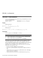
4.1 Device Attributes Report (DAR)
The Device Attributes Report identifies the LA75 Plus Companion Printer to
the host. During setup the user may specify that the printer identify itself as a
generic level 2 printer or as a previous model Digital printer. See DAR in the
Command Dictionary for more information.
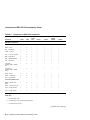
When the Printer ID setup feature is set to conformance level 2, the generic
DAR response is returned. The generic DAR response always begins with
Ps1 = ?72. Subsequent parameters are shown in Table 4–1. Parameters are
separated by a semicolon (;).
Status and Error Reporting for the LA75 Plus Companion Printer 4–1
Status and Error Reporting for the LA75 Plus Companion Printer
4.1 Device Attributes Report (DAR)
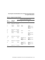
Table 4–1 Generic DAR Replies
Ps
Description
Comment
1
Color
Sent only if a color ribbon is installed
4
Sixels
5
Katakana extension
6
Sheet feeder
Sent only if the sheet feeder is installed
7
Dynamically Reloadable
Character Sets (DRCS), also
known as ‘‘download extension’’
Sent only if downline load capability is
enabled by the setup facility
12
Hebrew extension
23
Metric line spacing extension
24
Greek extension
26
Turkish extension
When the Printer ID setup feature is set to LA50, LA120, or LA210, an alias
DAR response is returned. The alias DAR responses are shown in Table 4–2.
Parameters are separated by a semicolon (;).
Table 4–2 Alias DAR Replies
Ps1
Additional
Parameter
?2
?10
?17
Printer ID Selection
LA120
3
LA210
LA50
4.2 Secondary Device Attributes Report (DA2R)
The Secondary Device Attributes Report (DA2R) sent by the LA75 Plus
Companion Printer uses the value 54 for parameter Ps1. This value identifies
the printer model as the LA75 Plus Companion Printer. Parameter Ps2
provides the firmware version. There are no additional parameters.
4–2 Status and Error Reporting for the LA75 Plus Companion Printer
Status and Error Reporting for the LA75 Plus Companion Printer
4.3 Device Status Report (DSR)
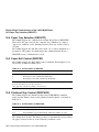
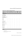
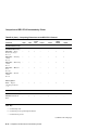
4.3 Device Status Report (DSR)
The codes generated by the LA75 Plus Companion Printer for the extended
Device Status Report (DSR) are given in Table 4–3. When the LA75 Plus
Companion Printer sends more than one code, only the first is preceded by a
question mark ( ? ).
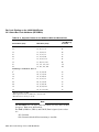
Table 4–3 DSR Codes
Ps
Description
Reference
?20
No malfunction
?21
Hardware failure (State)
?22
Communication failure (Event)
?23
Input buffer overflow (Event)
?24
Printer deselected (State)
?26
Cover open (State)
?27
Paper out (State)
?30
ASF installed — no ASF error (State)
?32
Paper jam or ASF error (State)
?40
Character set not available (Event)
Section 4.3.1
?42
Downline load error (Event)
Section 4.3.2
?45
Character beyond right margin (Event)
?55
Alternate protocol error (Event)
Section 11.3.3
?57
First report since initialization (Event)
Section 4.3.4
Definitions for ‘‘Event’’ and ‘‘State’’ in Table 4–3 are given in the Command
Dictionary, under DSR.
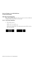
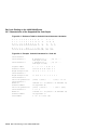
The following table gives two DSR examples:
Extended Report
Meaning
ESC [ 0 n ESC [ ? 20 ; 30 n
No error, ASF installed
ESC [ 3 n ESC [ ? 32 n
ASF installed, cannot clear paper path
Status and Error Reporting for the LA75 Plus Companion Printer 4–3
Status and Error Reporting for the LA75 Plus Companion Printer
4.3 Device Status Report (DSR)
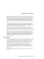
4.3.1 Character Set Not Available
The character set not available code is sent if the device attempts to print from
a character set that has been addressed by Select Character Set (SCS), but is
not available in any print density, from any source. Sources include built-in,
cartridge, and downloaded fonts.
4.3.2 Downline Load Error
A downline load error is sent under any of the following conditions:
•
The downloaded font file sent to the printer exceeds the printer’s download
capacity.
•
The entire download sequence is ignored. See DECDLD (download font) in
the Command Dictionary.
•
A DECDLD sequence is received, but the printer has been set to extended
input buffer size (no download capability) by the setup facility.
4.3.3 Alternate Protocol Error
The alternate protocol error code is sent by the printer if a user attempts to
select an alternate protocol that is not available in the printer.
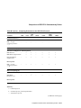
4.3.4 Initialization Messages
Whenever the LA75 Plus Companion Printer completes a power-on sequence,
and the setup feature DEC 9 (Initialization Message) is enabled, an unsolicited
extended Device Status Report (DSR) is sent, reflecting the state of the LA75
Plus Companion Printer at this point. The parameter value of the initial brief
report is Device Ready (Ps = 0) or Device Not Ready (Ps = 3), as appropriate.
The first parameter value of the extended report uses the ‘‘First report since
initialization’’ value from Table 4–3. If any additional error conditions are
present, the parameter values for these errors are also reported.
Table 4–4 shows the possible initialization messages.
Table 4–4 Initialization Messages
Extended Report
Meaning
ESC [ 0 n ESC [ ? 5 7 ; 2 0 n
Printer just switched on, ready to print
ESC [ 0 n ESC [ ? 5 7 ; 2 0 ; 3 0 n
Printer just switched on, ready to print,
ASF installed
ESC [ 3 n ESC [ ? 5 7 ; 2 7 n
Printer just switched on, paper out
4–4 Status and Error Reporting for the LA75 Plus Companion Printer
Status and Error Reporting for the LA75 Plus Companion Printer
4.3 Device Status Report (DSR)
If an error condition other than paper out exists when the printer is powered
up (hardware failure; cover open; carriage error; ASF installed, paper path
cannot be cleared), the initialization message is not sent until the error
condition is cleared.
The extended report is sent after the initial XON character is sent, following a
power-up. It is provided for applications or symbionts that need to know if the
device has been powered on recently and may be reset to an unknown state.
This feature can be enabled or disabled during setup. Refer to Section A.4 for
information on the interaction of this feature with automatic port selection.
Status and Error Reporting for the LA75 Plus Companion Printer 4–5
5
Fonts and Character Attributes on the
LA75 Plus Companion Printer
This chapter gives information on:
•
The built-in font repertory, Section 5.1
•
Additional character sets, Section 5.2
•
Cartridge font repertory, Section 5.3
•
Select Graphic Rendition (SGR) command for cartridge font selection,
Section 5.4
•
Font status reporting, Section 5.5
•
Density selection, Section 5.6
•
Download font, Section 5.7
•
Slant, Section 5.8
•
Bar code printing, Section 5.9
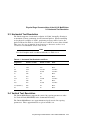
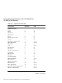
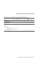
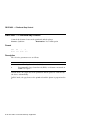
5.1 Built-In Font Repertory
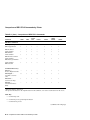
The built-in font repertory of the LA75 Plus Companion Printer includes
all character sets listed in Table 5–1 (at all pitches and densities), with two
exceptions:
•
ISO Latin-2 Supplemental
•
ISO Latin-Cyrillic Supplemental
These two character sets are supported by means of a cartridge, and are
selectable by DECAUPSS.
Fonts and Character Attributes on the LA75 Plus Companion Printer 5–1
Fonts and Character Attributes on the LA75 Plus Companion Printer
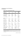
5.1 Built-In Font Repertory
Table 5–1 Supported Character Sets
I2 F Designator
Characters
Code
British
A
4/1
ASCII
B
4/2
DEC Dutch
4
3/4
DEC Finnish
5
3/5
French
R
5/2
DEC French-Canadian
9
3/9
K
4/11
"4
2/2, 3/4
DEC 7-Bit Hebrew
%=
2/5, 3/13
ISO Italian
Y
5/9
%4
2/5, 3/4
JIS Katakana
I
4/9
JIS Roman
J
4/10
DEC Norwegian/Danish
6
3/6
ISO Spanish
Z
5/10
DEC Swedish
7
3/7
DEC Swiss
=
3/13
`
6/0
%5
2/5, 3/5
Character Set
94-Character Sets
German
DEC Hebrew Supplemental
1
1
Legal
1
Norwegian/Danish
1
DEC Supplemental
DEC Technical
1
>
3/14
DEC Special Graphics
0
3/0
DEC Portuguese
%6
2/5, 3/6
%2
2/5, 3/2
DEC 8-Bit Turkish Supplemental
%0
2/5, 3/0
DEC Greek Supplemental1
"?
2/2, 3/15
1
DEC 7-Bit Turkish
1
1 Character
sets that can be designated by DECAUPSS
(continued on next page)
5–2 Fonts and Character Attributes on the LA75 Plus Companion Printer
Fonts and Character Attributes on the LA75 Plus Companion Printer
5.1 Built-In Font Repertory
Table 5–1 (Cont.) Supported Character Sets
I2 F Designator
Characters
Code
A
4/1
B
4/2
ISO Latin-Greek Supplemental
F
4/6
ISO Latin-Hebrew Supplemental1
H
4/8
L
4/12
M
4/13
Character Set
96-Character Sets
ISO Latin-1 Supplemental1
1
ISO Latin-2 Supplemental
1
ISO Latin-Cyrillic Supplemental
1
1
ISO Latin-5 Supplemental
1 Character
sets that can be designated by DECAUPSS
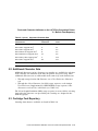
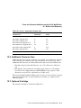
5.2 Additional Character Sets
Additional character sets in a character set cartridge are available for selection
if the cartridge was installed at the time the printer was powered up. These
additional character sets are addressable in the same way as the built-in sets:
•
Through setup selection (G0 Character set or User Preference Character
set)
•
Through the Select Character Set (SCS) escape sequence or the Assign
User Preference Supplemental Set (DECAUPSS) escape sequence if the
character set selected is a valid choice (see Table 5–1).
The Select Graphic Rendition (SGR) escape sequence is not needed for selecting
fonts when the character sets provided by the cartridge are designed in the
built-in typestyle.
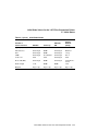
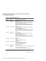
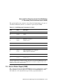
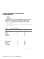
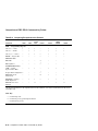
5.3 Cartridge Font Repertory
Cartridge fonts that are available are listed in Table 5–2.
Fonts and Character Attributes on the LA75 Plus Companion Printer 5–3
Fonts and Character Attributes on the LA75 Plus Companion Printer
5.3 Cartridge Font Repertory
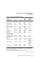
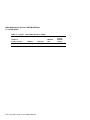
Table 5–2 Available Cartridge Fonts
Part
Number
Cartridge
Name
LA75Y-CA
Letter
Gothic Font
DEC PPL2 mode:
ASCII, 14 National Replacement Character (NRC)1 sets,
DEC Supplemental, Legal, ISO Latin-1 Supplemental
Proprinter mode, IBM code pages:
USA (437), Multilingual (850), Portugal (860), Norway
(865), Spain (220), Canada-French (863), German GS
(190)
LA75Y-CB
Orator Font
DEC PPL2 mode:
ASCII, 14 NRC1 sets, DEC Supplemental, Legal, ISO
Latin-1 Supplemental
Proprinter mode, IBM code pages:
USA (437), Multilingual (850), Portugal (860), Norway
(865), Spain (220), Canada-French (863), German GS
(190)
LA75Y-CC
Prestige
Elite Font
DEC PPL2 mode:
ASCII, 14 NRC1 sets DEC Supplemental, Legal, ISO
Latin-1 Supplemental
Proprinter mode, IBM code pages:
USA (437), Multilingual (850), Portugal (860), Norway
(865), Spain (220), Canada-French (863), German GS
(190)
LA75Y-CD
OCR-A Font
DEC PPL2 mode:
ASCII
Proprinter mode, IBM code page:
USA (437)
LA75Y-CE
OCR-B Font
DEC PPL2 mode:
ASCII, ISO Latin-1 Supplemental
Proprinter mode, IBM code pages:
USA (437), Multilingual (850)
LA75Y-CF
ISO Latin-2
Cyrillic
Hebrew
DEC PPL2 mode:
ISO Latin-2 Supplemental, ISO Latin-Cyrillic Supplemental
Character Sets in the Cartridge
Proprinter mode, IBM code pages:
ISO Latin-2 (852), Russian (866), Hebrew (862)
1 For the list of National Replacement Character (NRC) sets that are available, see Appendix A in
the Digital ANSI-Compliant Printing Protocol Level 2 Programming Reference Manual.
(continued on next page)
5–4 Fonts and Character Attributes on the LA75 Plus Companion Printer
Fonts and Character Attributes on the LA75 Plus Companion Printer
5.3 Cartridge Font Repertory
Table 5–2 (Cont.) Available Cartridge Fonts
Part
Number
Cartridge
Name
LA75Y-CG
ISO Latin-2
Cyrillic
HebrewDavid
Character Sets in the Cartridge
DEC PPL2 mode:
ISO Latin-2 Supplemental,
ISO Latin-Cyrillic Supplemental
Proprinter mode, IBM code pages:
ISO Latin-2 (852), Russian (866), Hebrew (862)
A comprehensive listing of the contents of the installed cartridge is performed
by the printer in setup mode.
For details of other cartridges that may be available, contact your Digital sales
representative.
The LA75 Plus Companion Printer applies all built-in algorithmic
transformations (bold, slant, density, underlining, and so on) to the alternative
typestyle or character set in the same way as it does to the built-in fonts. All
characters in the alternative typestyle or character sets can be printed at any
of the horizontal pitches supported by the printer.
5.4 Select Graphic Rendition (SGR) — Cartridge Font
Selection
The supported font selection Ps values for Select Graphic Rendition (SGR) are
given in Table 5–3.
Table 5–3 SGR Values for Cartridge Font Selection
Ps
Assignment
10
Built-in typestyle, downloaded font, or character set cartridge
11–16
Downloaded font
17
Cartridge typestyle or downloaded font
18–19
Downloaded font
Each downloaded font file is assigned one of the above SGR numbers. Different
downloaded font files may be assigned the same SGR if they are of different
character sets or different densities.
Fonts and Character Attributes on the LA75 Plus Companion Printer 5–5
Fonts and Character Attributes on the LA75 Plus Companion Printer
5.5 Font Status Report (DECFSR)
5.5 Font Status Report (DECFSR)
The SGR parameter, described under DECFSR in the Command Dictionary,
is always 17 if a font cartridge is installed. DECFSR does not report built-in
fonts or downloaded fonts.
5.6 Density Selection (DECDEN)
Supported Ps values for DECDEN are given in Table 5–4.
Table 5–4 DECDEN Ps Selection
Ps
Selection
0
Selects the default (draft) print density (highest speed).
1
Selects draft print density (highest speed).
2
Selects letter-quality print density (highest quality).
3
Select memo, falls back to near letter-quality print quality.
4
Selects near letter-quality print quality.
Printing in draft and letter-quality requires dedicated fonts. Near letter-quality
is generated algorithmically from the draft font.
Note
There is an interaction between DECDEN and the setup feature
Generic 5 (Print Quality Control).
If the Print Quality Control feature is set to ‘‘software control,’’
DECDEN is active. If the Print Quality Control feature is set to ‘‘Draft
locked’’ or ‘‘LQ locked,’’ the print quality is locked to draft or LQ and
subsequent DECDEN commands are stored. When the print quality is
unlocked by the front panel switch, the LA75 Plus Companion Printer
processes the stored DECDEN command.
5.7 Download Font (DECDLD)
The LA75 Plus supports the values given in Table 5–5 for the DECDLD
parameters Pu (font usage), Pss (font set size), Pcmw and Pcmh (character cell
matrix size), and only the combinations given in Table 5–5 are supported.
5–6 Fonts and Character Attributes on the LA75 Plus Companion Printer
Fonts and Character Attributes on the LA75 Plus Companion Printer
5.7 Download Font (DECDLD)
Any sequence with other values or any other combination of values is ignored
or changed to a valid configuration as given in Table 5–6.
Table 5–5 DECDLD Recommended Parameters Matrix
Pu
Font Usage
Pss
Font Set Size
Pcmw
Matrix Width
Pcmh
Matrix Height
1
1
9
24
Normal text
draft
1
3
27
24
Normal text
letter-quality
2
1
12
30
Full cell draft
2
3
36
30
Full cell letterquality
Print Density
Table 5–6 DECDLD Acceptable Parameters Matrix
Pu
Font Usage
Pss
Font Set Size
Pcmw
Matrix Width
Pcmh
Matrix Height
1
0
9
24
Normal text
draft
2
0
12
30
Full cell draft
1
0 or 1
12
30
Normal text
draft
1
3
36
30
Normal text
letter-quality
Print Density
The LA75 Plus font file download capability is limited by the following
considerations :
•
The LA75 Plus supports font file downloading if the input buffer size is
configured to standard size by the setup facility.
•
The LA75 Plus supports two font buffers only. As a result, only the Pfn
‘‘Font Number’’ values 1 and 2 are supported, and any other value causes
the DECDLD sequence to be ignored.
•
Each buffer has sufficient capacity for one full-cell 96-character character
set.
Fonts and Character Attributes on the LA75 Plus Companion Printer 5–7
Fonts and Character Attributes on the LA75 Plus Companion Printer
5.7 Download Font (DECDLD)
•
If the input buffer size is configured to extended size by the setup facility,
the LA75 Plus has no download capability. As a result, any DECDLD
sequence is ignored.
5.8 Slant
The LA75 Plus supports the Select Graphic Rendition (SGR) attribute for
slant by algorithmically slanting the characters. See SGR in the Command
Dictionary.
5.9 Bar Code Printing
The LA75 Plus Companion Printer supports built-in bar code 3 of 9 through
the DECBAR and DECSBCA commands.
5.9.1 Select Bar Code Attributes (DECSBCA)
Table 5–7 shows the bar code attributes supported by the LA75 Plus
Companion Printer.
Table 5–7 Bar Code Attributes
Default if
Zero
Parameter
Description
Supported Values
Pn2
Narrow bars and spaces
9 (0.0125 inch, 4.7 pitch)
18 (0.025 inch, 2.3 pitch)
9
Pn3
Quiet zone
180 (0.25 inch, leading and
trailing edges)
180
Pn4
Wide bars and spaces
27 (0.0375 inch, 4.7 pitch)
54 (0.075 inch, 2.3 pitch)
27
Pn5
Intercharacter gap
18 (0.025 inch, 4.7 pitch)
36 (0.050 inch, 2.3 pitch)
18
Pn6
Height of bars
96 (0.133 inch)
96
Ps7
Control characters
None (parameter is ignored)
Ps8
Orientation
None (parameter is ignored)
Ps9
Human-readable
characters
All Ps9 values for DECSBCA in
the Command Dictionary
The LA75 Plus Companion Printer ignores the following values:
•
Received values for Pn3 and Pn6. The printer always used the value given
in Table 5–7.
5–8 Fonts and Character Attributes on the LA75 Plus Companion Printer
Fonts and Character Attributes on the LA75 Plus Companion Printer
5.9 Bar Code Printing
•
Parameter Ps7. The LA75 Plus Companion Printer does not support
control characters in bar codes.
•
Parameter Ps8. The LA75 Plus Companion Printer always uses portrait
orientation.
The values assigned to Pn2, Pn4, and Pn5 must be consistent with the pitch.
Table 5–8 shows the allowed combinations of Pn parameters and pitch.
Table 5–8 Allowed Combinations of Pn Values and Pitch
Pn2
Pn4
Pn5
Pitch
9
27
18
4.7
18
54
36
2.3
Human-readable characters are printed centered below the bar code equivalent.
They are printed at 10 characters/inch in the currently selected print density,
with no printing attribute enabled.
Fonts and Character Attributes on the LA75 Plus Companion Printer 5–9
6
Sixel Graphics Considerations on the
LA75 Plus Companion Printer
This chapter explains the graphics resolution capability of the LA75 Plus
Companion Printer.
6.1 Graphics Resolution
Table 6–1 shows the values that the printer uses for macro value Ps1 of the
Sixel Graphics mode protocol selector.
Table 6–1 Graphics Pitch Fallbacks
Macro Value
Horizontal Grid
Size (Inches)
Aspect Ratio
(Vertical:Horizontal)
0 or none
1/144 in (0.0069)
200:100
1
1/144 in (0.0069)
200:100
2, fall back to:
1/180 in (0.0056)
250:100
3, fall back to:
1/180 in (0.0056)
250:100
4
1/180 in (0.0056)
250:100
5, fall back to:
1/144 in (0.0069)
200:100
6, fall back to:
1/144 in (0.0069)
200:100
7, fall back to:
1/144 in (0.0069)
200:100
8, fall back to:
1/144 in (0.0069)
200:100
9
1/72 in (0.0139)
100:100
In Table 6–1 the comments ‘‘fall back to:’’ mean that for the given macro value,
the horizontal grid size and aspect ratio values on that row are fallback values.
Sixel Graphics Considerations on the LA75 Plus Companion Printer 6–1
Sixel Graphics Considerations on the LA75 Plus Companion Printer
6.1 Graphics Resolution
Table 6–2 shows the horizontal grid size (HGS) and vertical grid size (VGS)
fallbacks relative to the requested horizontal grid size and the aspect ratio.
The printer attempts to preserve the requested aspect ratio without exceeding
the requested horizontal grid size (as defined by Pn3 of the protocol selector).
The aspect ratio is provided by Ps1 or Set Raster Attributes (DECGRA).
First the printer ensures that the aspect ratio is one of the supported values
(1:1, 2:1, 2.5:1):
•
If aspect ratio is less than 1.5:1, fall back to 1:1
•
If aspect ratio is greater than or equal to 1.5:1 and less than 2.25:1, fall
back to 2:1
•
If aspect ratio is greater than or equal to 2.25:1, fall back to 2.5:1
Then the printer computes the HGS and VGS values that best match the
aspect ratio and requested Pn3 value.
6–2 Sixel Graphics Considerations on the LA75 Plus Companion Printer
Sixel Graphics Considerations on the LA75 Plus Companion Printer
6.1 Graphics Resolution
Table 6–2 Graphics Grid Size Fallbacks
Vertical Grid Size by Aspect
Ratio with HGS Fallbacks (If Any)
Pn3
Decipoints
Horizontal
Grid Size
0 or none
No change to HGS and VGS defined by Ps1
1, 2 and 3
Fall back to 4 decipoints
4
1/180 in
1/180 in
1/90 in
1/72 in
5
1/144 in
1/144 in
1/72 in
VGS fall back to
1/72 in
HGS fall back to
1/180 in
6, 7
Fall back to 5 decipoints
8
1/90 in
1/45 in
1/36 in
9
Fall back to 8 decipoints
10
1/72 in
1/36 in
VGS fall back to
1/36 in
HGS fall back to
1/90 in
11–15
Fall back to 10 decipoints
16
1/45 in
VGS fall back to
1/36 in
HGS fall back to
1/72 in
VGS fall back to
1/36 in
HGS fall back to
1/90 in
17–19
Fall back to 16 decipoints
20
1/36 in
VGS fallback to
1/36 in
HGS fall back to
1/72 in
VGS fall back to
1/36 in
HGS fall back to
1/90 in
> 20
Fall back to 20 decipoints
1:1
1/90 in
1/72 in
1/45 in
1/36 in
2:1
2.5:1
Sixel Graphics Considerations on the LA75 Plus Companion Printer 6–3
7
Control Characters for the LA75 Plus
Companion Printer
This chapter describes the control characters for the LA75 Plus Companion
Printer and their functions. The control characters are:
•
Bell, described in Section 7.1
•
EOT, described in Section 7.2
7.1 Bell
The LA75 Plus Companion Printer has an audio indicator, or bell. The bell
can be configured using setup to sound one beep, sound three beeps, sound
continuously, or not to sound at all when an error occurs. When the device
receives a BEL (Bell) control character, it always sounds one beep.
7.2 EOT
When Disconnect on EOT is enabled by the setup facility, the DTR signal on
the serial port is dropped for 5 seconds when the EOT control code is received.
This feature applies only if the serial port is active. See the setup feature
Disconnect on EOT (DEC 8), in the LA75 Plus Companion Printer Installation
and User Guide.
Control Characters for the LA75 Plus Companion Printer 7–1
Part II
LA310 MultiPrinter
Part II of the Digital ANSI-Compliant Printing Protocol Level 2 Programming
Supplement describes the DEC PPL2 protocol as implemented by the LA310
MultiPrinter.
•
Chapter 8 describes the basic features and characteristics of the LA310
MultiPrinter.
•
Chapter 9 describes the the printing of the physical page on the LA310
MultiPrinter.
•
Chapter 10 describes the initial state of the printer.
•
Chapter 11 describes how status and error messages are handled.
•
Chapter 12 describes the fonts and font cartridges available on the LA310
MultiPrinter.
•
Chapter 13 describes the sixel graphics considerations for the LA310
MultiPrinter.
•
Chapter 14 describes the control characters and their functions on the
LA310 MultiPrinter.
8
General Information About the LA310
MultiPrinter
This chapter contains the following information about the LA310 MultiPrinter:
•
Description of the LA310 MultiPrinter, Section 8.1
•
Protocol extensions and exceptions, Section 8.2
•
Alternate protocols, Section 8.3
•
Cartridges, Section 8.4
8.1 Description of the LA310 MultiPrinter
The LA310 MultiPrinter is a wide-carriage impact dot-matrix printer, designed
for general business applications. It has flexible paper handling, and is capable
of printing on continuous pinfeed paper, single sheets, multiple-part forms,
and envelopes. A Pull Tractor is available as an option for greater accuracy
in positioning multiple-part forms. The print quality is suitable for word
processing in a small-to-medium computer environment.
The LA310 MultiPrinter:
•
Is a 9-pin printer.
•
Has a Document on Demand capability (automatic or manual), which
prevents wasting forms or paper between printing jobs.
•
Has an Automatic Viewing capability, which allows the user to see the last
printed line after a job has finished.
•
Can be connected at the same time to serial and parallel ports, and
switches automatically between them when data is received.
•
Has protocol switching. The protocol can be switched from the front panel
or by software (see Section 8.3). Also, different protocols can be assigned
to the serial and parallel ports. The printer will switch to the assigned
protocol when a port is selected.
General Information About the LA310 MultiPrinter 8–1
General Information About the LA310 MultiPrinter
8.1 Description of the LA310 MultiPrinter
•
Has a slot for optional cartridges for one of the following:
Additional protocol emulations
Fonts
Additional character sets
Refer to Section 8.4.
For information about installing and using the LA310 MultiPrinter, see the
LA310 MultiPrinter Installation/User’s Guide.
8.2 DEC PPL2 Extensions and Exceptions
Note
References are made in this manual to Chapter 7 (Command
Dictionary) of the associated manual Digital ANSI-Compliant Printing
Protocol Level 2 Programming Reference Manual. For brevity in this
document, that chapter is called ‘‘Command Dictionary.’’
The implementation of DEC PPL2 on the LA310 MultiPrinter involves a
number of extensions and exceptions, which are summarized in Table 8–1
and Table 8–2. For further information, see Table 11–1, and also refer to the
Command Dictionary.
Table 8–1 DEC PPL2 Extensions
Extensions
Download font (DECDLD)
Sixel graphics
Hebrew character sets
Katakana character set
Greek character sets
Turkish character sets
Metric line spacing
8–2 General Information About the LA310 MultiPrinter
General Information About the LA310 MultiPrinter
8.2 DEC PPL2 Extensions and Exceptions
Table 8–2 DEC PPL2 Exceptions
Exceptions
Bell
LA210, LA120, LA50 alias Device Attributes Report (DA) parameters
Control Representation Mode (CRM)
Protocol switching
Horizontal Page Width Alignment (DECHPWA)
Loading Factory NVR (DECFNVR)
Answerback (DECLANS, ENQ)
Automatic Test Mode (DECSATM, DECCKSR)
8.3 Alternate Protocols Supported by the LA310 MultiPrinter
This part of the manual describes the DEC PPL2 protocol as implemented on
the LA310 MultiPrinter. The LA310 MultiPrinter also emulates the protocols
for printing on the following devices:
•
IBM Proprinter III
•
Epson FX-1050
The protocol mode is changed using either the Select Other Coding System
(SOCS)/Return from Other Coding System (ROCS) command combination or
the IBM Proprinter Emulation Mode (DECIPEM) command. These commands
are described in the Command Dictionary.
Table 8–3 lists the SOCS/ROCS command sequence to enter emulation mode
for each of the protocols supported by the LA310 MultiPrinter.
Table 8–3 SOCS/ROCS Commands for Each Emulation Mode
Emulation Mode
SOCS/ROCS Command
IBM Proprinter
ESC % =
ESC % SP 2
ESC % @
EPSON ESC/P
Return to DEC PPL2
General Information About the LA310 MultiPrinter 8–3
General Information About the LA310 MultiPrinter
8.4 Cartridges Supported by the LA310 MultiPrinter
8.4 Cartridges Supported by the LA310 MultiPrinter
The LA310 MultiPrinter has a slot for an optional cartridge. Cartridges are
available to supply the following additional capabilities:
•
Fonts
•
Protocol emulations
•
Additional character sets
To insert the cartridge, turn the printer power off, insert the cartridge, and
turn the power back on. If you insert the cartridge while the printer is
powered on, the printer may not be able to select and use the cartridge. Select
PRINT while in setup mode to print full details of the contents of the installed
cartridge. See the LA310 MultiPrinter Installation/User’s Guide for further
information about installing and using cartridges.
8–4 General Information About the LA310 MultiPrinter
9
Physical Page Characteristics of the
LA310 MultiPrinter
This chapter explains how the LA310 MultiPrinter printer handles the transfer
of the logical page in memory to the physical paper. Topics include:
•
Paper handling, Section 9.1
•
Response to a Form Feed request, Section 9.2
•
Horizontal text resolution, Section 9.3
•
Vertical text resolution, Section 9.4
•
Limits on partial line motion, Section 9.5
•
Tab support, Section 9.6
In this chapter the top of form paper position is defined as the position of line
1 on the page. This position does not change with the top margin setting.
The form length is defined by the setup feature or by the Set Lines Per Page
(DECSLPP) command.
9.1 Paper Handling
This section summarizes the paper feed modes and loading processes for the
LA310 MultiPrinter.
Note
In both paper-feed modes, if paper is loaded before the printer is
powered on, the paper position is assumed to be the top of form.
Physical Page Characteristics of the LA310 MultiPrinter 9–1
Physical Page Characteristics of the LA310 MultiPrinter
9.1 Paper Handling
Fanfold Paper — Rear Feed/Top or Rear Output (Push Tractor Mode and Pull
Tractor Option)
Paper is considered autoloaded when the printer loads it automatically at
power-up or when the user presses the Form Feed (FF) button.
Paper is considered manually loaded when the user inserts it using the platen
knob.
The LA310 MultiPrinter can detect the top of the first form only.
The LA310 MultiPrinter uses the form length, as determined by the setup
feature or by the Set Lines Per Page (DECSLPP) command, to compute the
tops of forms other than the first.
Cut Sheet Paper — Manual Feed/Top Insertion and Top Output (Friction
Mode)
Paper is considered autoloaded when the printer loads it automatically at
power-up or when the user presses the Form Feed (FF) button.
Paper is considered manually loaded when the user inserts it using the platen
knob.
9.2 Response to Form Feed (FF)
The following information refers to paper motion when the Form Feed (FF)
control code is received; actions that occur when the user presses the Form
Feed (FF) button are not covered.
Fanfold Paper — Rear Feed
When paper is autoloaded, Form Feed (FF) advances the paper to the next top
of form.
Cut Sheet Paper — Manual Feed
If paper is not currently loaded, Form Feed (FF) is stored and does not load
paper. If paper is currently loaded, Form Feed (FF) ejects the current sheet if
the physical paper length is equal to, or shorter than, the logical paper length,
as defined during setup or by DECSLPP. If the physical paper length is larger
that the logical paper length, Form Feed (FF) advances paper to the next top
of form.
9–2 Physical Page Characteristics of the LA310 MultiPrinter
Physical Page Characteristics of the LA310 MultiPrinter
9.3 Horizontal Text Resolution
9.3 Horizontal Text Resolution
The LA310 supports a horizontal resolution of 1/7920" internally, allowing it
to maintain accurate positioning for all horizontal pitches. When translating
to the physical resolution of 1/720", positioning accuracy will be lost for the
pitches indicated in Table 9–1, but in all cases it will be no more than 1/1440".
This error does not accumulate from character to character so there is no
overall error accumulation across a line of text.
Note
For Sixel Graphics mode resolution fallbacks, see Table 13–2.
Table 9–1 Horizontal Text Resolution and Error
Target Pitch
Actual in 1/7920"
Actual in 1/720"
Error
5
1584
144
None
6
1320
120
None
6.6
1200
109.091
±1/1440"
8.25
960
87.273
±1/1440"
10
792
72
None
12
660
60
None
13.2
600
54.545
±1/1440"
15
528
48
None
16.5
480
43.637
±1/1440"
17.1 (14/240")
462
42
None
18
440
40
None
9.4 Vertical Text Resolution
The LA310 MultiPrinter supports the metric line spacing parameters under
Set Vertical Pitch (DECVERP) in the Command Dictionary.
The LA310 MultiPrinter uses approximations for the metric line spacing
parameters. These approximations are given in Table 9–2.
Physical Page Characteristics of the LA310 MultiPrinter 9–3
Physical Page Characteristics of the LA310 MultiPrinter
9.4 Vertical Text Resolution
Table 9–2 Text Vertical Pitch Fallbacks
Target Pitch
Actual in
1/2160"
1 lpcm (2.54 lpi)
Fallback pitch
Error per A4 page
850
1.0046318 lpcm
2.54117647 lpi
0.14 mm
2 lpcm (5.08 lpi)
425
2.00092635 lpcm
5.08235294 lpi
0.13 mm
4 lpcm (10.16 lpi)
213
3.99245869 lpcm
10.14084507 lpi
0.57 mm
9.5 Limits on Partial Line Motion
The LA310 MultiPrinter limits the Partial Line Up (PLU) count to 12, due to
mechanical limitations.
When using cut sheet media, due to mechanical limitations in the LA310
MultiPrinter, partial line movement is limited to two levels between 125 mm
and 50 mm from the bottom of the sheet. The number of levels of partial line
movement is maintained similarly, but with a limit of 2 instead of 12.
When the printer detects the end of the media, when using continuous or
cut-sheet media, although printing is enabled, the Partial Line Up (PLU)
command and the Partial Line Down (PLD) command are not executed. As a
result, there is no partial line motion for the last 50 mm of the media.
9.6 Tabs
The LA310 MultiPrinter supports a maximum of 256 horizontal tabs and a
maximum of 252 vertical tabs.
9–4 Physical Page Characteristics of the LA310 MultiPrinter
10
Initial State Values for the LA310
MultiPrinter
This chapter lists the values used by the LA310 MultiPrinter printer for:
•
A power-up reset or a recall of factory default values
•
The Select Conformance Level (DECSCL) command
•
The Soft Terminal Reset (DECSTR) or Reset to Initial State (RIS)
commands
10.1 Initial States
Table 10–1 lists the initial state values used by the LA310 MultiPrinter. The
printer always powers up in Ready mode if no error is detected.
Table 10–1 Initial State Values for LA310
Recall
Factory
Defaults
(Setup)
Variable or
Control Function
DECSCL
Power-Up
DECSTR
RIS
Protocol
Unchanged
NVM1
Unchanged
Port
Dependent
Origin (DECHPWA)
Unchanged
0
Unchanged
0
Vertical pitch
6 lpi
NVM
NVM
6 lpi
Horizontal pitch
10 cpi
NVM
NVM
10 cpi
Active position
Origin
Origin
Origin
Origin2
1 NVM
indicates that the initial state value is stored in the nonvolatile memory of the LA310.
2 Device
performs conditional form feed on exit from setup
(continued on next page)
Initial State Values for the LA310 MultiPrinter 10–1
Initial State Values for the LA310 MultiPrinter
10.1 Initial States
Table 10–1 (Cont.) Initial State Values for LA310
Variable or
Control Function
DECSCL
Power-Up
DECSTR
RIS
Recall
Factory
Defaults
(Setup)
Horizontal tabs3
Every eight
Every eight
Every eight
Every eight
Line Feed/New Line
Reset
NVM
NVM
Reset
CR/New Line Mode
Reset
NVM
NVM
Reset
SGR attributes
Disabled
Disabled
Disabled
Disabled
Density (DECDEN)
Draft
NVM
NVM
Draft
(Software
control)
Unidirectional Print
Mode
Reset
Reset
Reset
Reset
Vertical tabs4
Every line
Every line
Every line
Every line
G0 character set
ASCII
NVM
NVM
ASCII
G1 character set
ASCII
ASCII
ASCII
ASCII
G2 character set
User Pref.
User Pref.
User Pref.
User Pref.
G3 character set
User Pref.
User Pref.
User Pref.
User Pref.
GL character set
G0
G0
G0
G0
GR character set
G2
G2
G2
G2
User Preference Set
DEC Supp.
NVM
Unchanged
DEC Supp.
Autowrap Mode
Set
NVM
NVM
Set
Unsolicited status
reports
Disabled
Disabled
Unchanged
Disabled
Initialization Message
Unchanged
NVM
Unchanged
Disabled
Downloaded fonts
Deleted
None
Unchanged
None
Typestyle (SGR #)
10
NVM
NVM
10
Auto Advance
Unchanged
NVM
Unchanged
Disabled
3 Horizontal tabs are set every eight columns, starting with column 9 (9,17, . . . ). All entries in
the tab table are initialized. Initializing only those entries that are addressable on the currently
selected paper size is incorrect.
4 Vertical
tabs are set every line or Vertical Advance Increment (VAI). All entries in the tab table
are initialized. Initializing only those entries that are addressable on the currently selected paper
size is incorrect.
(continued on next page)
10–2 Initial State Values for the LA310 MultiPrinter
Initial State Values for the LA310 MultiPrinter
10.1 Initial States
Table 10–1 (Cont.) Initial State Values for LA310
DECSCL
Power-Up
DECSTR
RIS
Recall
Factory
Defaults
(Setup)
Paper Position at
power-up
Unchanged
Line 1
Unchanged
Line 1
CRM
Unchanged
Disabled5
Unchanged
Disabled
C1 Receive
8-Bit
8-Bit
Unchanged
8-Bit
Device ID (DA)
Unchanged
NVM
Unchanged
DEC PPL2
Form Length
11"
NVM
NVM
11"
Margins
Paper edge
Paper edge
Paper edge
Paper edge
Automatic Test Mode
Unchanged
Disabled
Unchanged
Disabled
Variable or
Control Function
5 When
CRM is enabled by software, it can only be disabled by software or by powering down the
printer. When CRM is enabled, the protocol switching commands that cause a power-up reset are
not performed. The LA310 can also enable DUMP printing from the printer front panel. This mode
cannot be disabled by software.
Initial State Values for the LA310 MultiPrinter 10–3
11
Status and Error Reporting for the LA310
MultiPrinter
This chapter explains how the LA310 MultiPrinter printer provides status
information and handles error conditions. The topics include:
•
Device Attributes Report, Section 11.1
•
Secondary Device Attributes Report, Section 11.2
•
Device Status Report, Section 11.3
Note
Device attribute and status reports are applicable only to the serial
interface. Reports are not sent across the parallel interface.
11.1 Device Attributes Report (DAR)
The Device Attributes Report identifies the LA310 MultiPrinter to the
host. During setup the user may specify that the printer identify itself as a
generic level 2 printer or as a previous model Digital printer. See DAR in the
Command Dictionary for more information.
When the Printer ID setup feature is set to conformance level 2, the generic
DAR response is returned. The generic DAR response always begins with
Ps1 = ?72. Subsequent parameters are shown in Table 11–1. Parameters are
separated by a semicolon ( ; ).
Status and Error Reporting for the LA310 MultiPrinter 11–1
Status and Error Reporting for the LA310 MultiPrinter
11.1 Device Attributes Report (DAR)
Table 11–1 Generic DAR Replies
Ps
Description
4
Sixels
5
Katakana character set
7
Dynamically Redefinable Character Sets (DRCS), also known as ‘‘download
font extension’’
12
Hebrew character set
23
Metric line spacing extension
24
Greek extension
26
Turkish extension
When the Printer ID setup feature is set to LA50, LA120, or LA210, an alias
DAR response is returned. The alias DAR responses are shown in Table 11–2.
Parameters are separated by a semicolon (;).
Table 11–2 Alias DAR Replies
Ps1
Additional
Parameter
?2
?10
Printer ID Selection
LA120
3
?17
LA210
LA50
11.2 Secondary Device Attributes Report (DA2R)
The Secondary Device Attributes Report (DA2R) identifies the following
information about the LA310:
•
The printer model
•
The major and minor firmware revision
•
The presence of protocols other than DEC PPL2
•
The firmware edit revision
The parameters of the DA2R response cannot be changed by software or
from the front panel. Table 11–3 lists the DA2R parameters supported by the
LA310.
11–2 Status and Error Reporting for the LA310 MultiPrinter
Status and Error Reporting for the LA310 MultiPrinter
11.2 Secondary Device Attributes Report (DA2R)
The optional pull tractor cannot be detected by the LA310 firmware because of
a hardware limitation; therefore, it cannot be reported by the DA2R.
Table 11–3 DA2R Response Parameters for LA310
Character
Form
Code
Description
Ps1
59
3/5 3/9
LA310
Ps2
xx
3/x 3/x
Firmware version x.x
10
3/1 3/0
Version 1.0-yy
Ps3
0
3/0
Always reported as ‘‘0’’
Ps4
20
3/2 3/0
IBM + EPSON FX-1050 emulation
??
3/? 3/?
IBM + Optional emulation†
Ps5
yy
3/y 3/y
Firmware edit revision yy
00
3/0 3/0
Version x.x-00
†The value of Ps4 when an optional emulation cartridge is installed is equal to 4 plus the
parameter supplied by the emulation cartridge. The value of 4 reflects the IBM Proprinter III
emulation, which is always present. The EPSON FX-1050 emulation is assigned a value of 16,
making the normal value of Ps4 20 (4+16).
11.3 Device Status Report (DSR)
The codes generated by the LA310 MultiPrinter for the extended Device Status
Report (DSR) are given in Table 11–4. When the LA310 MultiPrinter sends
more than one code, only the first is preceded by a question mark ( ? ).
Status and Error Reporting for the LA310 MultiPrinter 11–3
Status and Error Reporting for the LA310 MultiPrinter
11.3 Device Status Report (DSR)
Table 11–4 DSR Codes
Ps
Description
Reference
?20
No malfunction
?22
Communication failure (Event)
?23
Input buffer overflow (Event)
?24
Printer deselected (State)
?26
Cover open (State)
?27
Paper out (State)
?40
Character set not available (Event)
Section 11.3.1
?42
Downline load error (Event)
Section 11.3.2
?45
Character beyond right margin (Event)
?55
Alternate protocol error (Event)
Section 11.3.3
?57
First report since initialization (Event)
Section 11.3.4
Definitions for ‘‘Event’’ and ‘‘State’’ in Table 11–4 are given in the Command
Dictionary, under DSR.
The following table gives two DSR examples:
Extended Report
Meaning
ESC [ 0 n ESC [ ? 20
No error
ESC [ 3 n ESC [ ? 24 ; 26 n
Printer offline; cover open
11.3.1 Character Set Not Available
This error occurs when a character is to be printed and the currently
designated character set is not available at any print density from any source,
including built-in, cartridge, or downloaded font files.
11.3.2 Download Font Error
This error occurs when Download Font (DECDLD) sequence is ignored because
of some error condition. Refer to the discussion of DECDLD in the Command
Dictionary.
11–4 Status and Error Reporting for the LA310 MultiPrinter
Status and Error Reporting for the LA310 MultiPrinter
11.3 Device Status Report (DSR)
Note
When the ‘‘Input Buffer’’ feature is set to 32K, no fonts can be
downloaded into the LA310 MultiPrinter and the DECDLD sequence is
ignored.
11.3.3 Alternate Protocol Error
This error occurs when an alternate protocol that is not available in the printer
(built-in or in a cartridge) is selected with the Select Other Coding System
(SOCS) command.
11.3.4 Initialization Messages
If the serial port becomes active when the automatic port selection is enabled,
and this feature is enabled with the INIT. REPORT feature in the DEC PPL2
sub-menu, an unsolicited extended Device Status Report (DSR) is issued
reflecting the state of the printer when the LA310 MultiPrinter completes a
power-on.
The parameter value of the initial brief report indicates ‘‘Device Ready’’ (Ps=0)
or ‘‘Device Not Ready’’ (Ps=3), as appropriate.
The first parameter value of the extended report uses the ‘‘First report since
initialization’’ value from Table 11–4. If any additional error conditions are
present, the parameter values for these errors are also reported.
Table 11–5 shows the possible initialization messages.
Table 11–5 Initialization Messages
Extended Report
Meaning
ESC [ 0 n ESC [ ? 5 7 ; 2 0 n
Printer ready to print; just switched on
ESC [ 3 n ESC [ ? 5 7 ; 2 6 n
Printer just switched on; cover open
ESC [ 3 n ESC [ ? 5 7 ; 2 7 n
Printer just switched on; paper out
If an error condition other than paper out exists when the printer is powered
up (hardware failure, carriage error), the initialization message is not sent
until the error condition is cleared.
The extended report is sent after the initial XON character is sent, following a
power-up. It is provided for applications or symbionts that need to know if the
device has been powered on recently and may be reset to an unknown state.
Status and Error Reporting for the LA310 MultiPrinter 11–5
Status and Error Reporting for the LA310 MultiPrinter
11.3 Device Status Report (DSR)
This feature can be enabled or disabled during setup. Refer to Section A.4 for
information on the interaction of this feature with automatic port selection.
11–6 Status and Error Reporting for the LA310 MultiPrinter
12
Fonts and Character Attributes on the
LA310 MultiPrinter
This chapter gives information on:
•
The built-in font repertory, Section 12.1
•
Additional character sets, Section 12.2
•
The optional cartridge, Section 12.3
•
Select Graphic Rendition (SGR) command for cartridge font selection,
Section 12.4
•
Density selection, Section 12.5
•
Download font, Section 12.6
•
Slant, Section 12.7
12.1 Built-In Font Repertory
The built-in font repertory of the LA310 MultiPrinter includes all character
sets listed in Table 12–1 (at all pitches and densities), with two exceptions:
•
ISO Latin-2 Supplemental
•
ISO Latin-Cyrillic Supplemental
These two character sets are provided in an optional cartridge. Refer to
Section 12.3.
Fonts and Character Attributes on the LA310 MultiPrinter 12–1
Fonts and Character Attributes on the LA310 MultiPrinter
12.1 Built-In Font Repertory
Table 12–1 Supported Character Sets
I2 F Designator
Characters
Code
British
A
4/1
ASCII
B
4/2
DEC Dutch
4
3/4
DEC Finnish
5
3/5
French
R
5/2
DEC French-Canadian
9
3/9
K
4/11
"4
2/2, 3/4
DEC 7-Bit Hebrew
%=
2/5, 3/13
ISO Italian
Y
5/9
%4
2/5, 3/4
JIS Katakana
I
4/9
JIS Roman
J
4/10
DEC Norwegian/Danish
6
3/6
ISO Spanish
Z
5/10
DEC Swedish
7
3/7
DEC Swiss
=
3/13
`
6/0
%5
2/5, 3/5
Character Set
94-Character Sets
German
DEC Hebrew Supplemental
1
1
Legal
1
Norwegian/Danish
1
DEC Supplemental
DEC Technical
1
>
3/14
DEC Special Graphics
0
3/0
DEC Portuguese
%6
2/5, 3/6
%2
2/5, 3/2
DEC 8-Bit Turkish Supplemental
%0
2/5, 3/0
DEC Greek Supplemental1
"?
2/2, 3/15
1
DEC 7-Bit Turkish
1
1 Character
sets that can be designated by DECAUPSS
(continued on next page)
12–2 Fonts and Character Attributes on the LA310 MultiPrinter
Fonts and Character Attributes on the LA310 MultiPrinter
12.1 Built-In Font Repertory
Table 12–1 (Cont.) Supported Character Sets
I2 F Designator
Characters
Code
A
4/1
B
4/2
ISO Latin-Greek Supplemental
F
4/6
ISO Latin-Hebrew Supplemental1
H
4/8
L
4/12
M
4/13
Character Set
96-Character Sets
ISO Latin-1 Supplemental1
1
ISO Latin-2 Supplemental
1
ISO Latin-Cyrillic Supplemental
1
ISO Latin-5 Supplemental
1 Character
1
sets that can be designated by DECAUPSS
12.2 Additional Character Sets
Additional character sets in a character set cartridge are available for selection
if the cartridge was installed at the time the printer was powered up. These
additional character sets are addressable in the same way as the built-in sets:
•
Through setup selection (G0 Character set or User Preference Character
set)
•
Through the Select Character Set (SCS) escape sequence or the Assign
User Preference Supplemental Set (DECAUPSS) escape sequence if the
character set selected is a valid choice (see Table 12–1)
The Select Graphic Rendition (SGR) escape sequence is not needed for selecting
fonts when the character sets provided by the cartridge are designed in the
built-in typestyle.
12.3 Optional Cartridge
The optional cartridge is described in Table 12–2.
Fonts and Character Attributes on the LA310 MultiPrinter 12–3
Fonts and Character Attributes on the LA310 MultiPrinter
12.3 Optional Cartridge
Table 12–2 Available Optional Cartridge
Part
Number
Cartridge
Name
Character Sets in the Cartridge
LA31X-CA
ISO Latin-2
Cyrillic
DEC PPL2 mode:
ISO Latin-2 Supplemental,ISO Latin-Cyrillic Supplemental
Proprinter and EPSON modes, IBM code pages:
ISO Latin-2 (852), Russian (866)
A comprehensive listing of the contents of the installed cartridge is performed
by the printer in setup mode.
For details of other cartridges that may be available, contact your Digital sales
representative.
The LA310 MultiPrinter applies all built-in algorithmic transformations (bold,
slant, density, underlining, and so on) to the alternative typestyle or character
set in the same way as it does to the built-in fonts. All characters in the
alternative typestyle or character sets can be printed at any of the horizontal
pitches supported by the printer.
12.4 Select Graphic Rendition (SGR) — Cartridge Font
Selection
In the LA310 MultiPrinter, all ten font selection parameter values of the Select
Graphic Rendition (SGR) command are assigned the built-in Courier typestyle.
Font cartridges, when present, override these default font assignments.
The LA310 MultiPrinter suports one font cartridge position. Each typestyle in
the font cartridge will provide an SGR parameter value that will be assigned
to the typestyle, overriding the default assignment of the built-in typestyle at
power-up. Each LA310 font cartridge may provide one or two typestyles.
12.5 Density Selection (DECDEN)
The LA310 MultiPrinter supports built-in fonts for the Draft, High-Speed
Draft, and Near Letter Quality 2 (NLQ2) densities. An additional Near Letter
Quality (NLQ1) font is generated algorithmically from the Draft font.
Table 12–3 specifies the supported values for the DECDEN command.
12–4 Fonts and Character Attributes on the LA310 MultiPrinter
Fonts and Character Attributes on the LA310 MultiPrinter
12.5 Density Selection (DECDEN)
Table 12–3 DECDEN Parameters for LA310
Ps
Selection
0
Selects High Speed Draft print density.
1
Selects High Speed Draft print density.
2
Selects Near Letter Quality 2 (NLQ2) print density.
3
Selects Draft print density.
4
Selects Near Letter Quality 1 (NLQ1) print density.
Note
There is an interaction between DECDEN and the PRINT QUALITY
feature in the GENERAL set-up menu.
If the PRINT QUALITY feature is set to ‘‘software control,’’ DECDEN is
active. If it is set to ‘‘HSD Locked,’’ ‘‘NLQ1 Locked,’’ or ‘‘NLQ2 Locked,’’
the print quality is locked to the appropriate setting and subsequent
DECDEN commands are stored. When the print quality is unlocked
by the front panel switch, the LA310 MultiPrinter processes the stored
DECDEN commands.
The bold, overline, and slant attributes are not available in High Speed Draft
(HSD) mode. When these attributes and the High Speed Draft density are
both specified, the LA310 MultiPrinter will temporarily use the Draft density
for printing.
12.6 Download Font—DECDLD
The Pss parameter of the DECDLD command indicates the print density for
the downloaded font. The font set sizes associated with the print densities
supported by the LA310 are given in Table 12–4. For more information on
DECDLD, refer to the Command Dictionary.
Table 12–4 DECDLD Font Set Sizes (Pss)
Pss
Print Density
0
Draft
(continued on next page)
Fonts and Character Attributes on the LA310 MultiPrinter 12–5
Fonts and Character Attributes on the LA310 MultiPrinter
12.6 Download Font—DECDLD
Table 12–4 (Cont.) DECDLD Font Set Sizes (Pss)
Pss
Print Density
1
Draft
3
Near Letter Quality 2
4
High Speed Draft
The Near Letter Quality (NLQ1) density for a downloaded font file is generated
algorithmically by the LA310 from the downloaded Draft font file.
The supported DECDLD matrix widths for the LA310 are given in Table 12–5.
Table 12–5 DECDLD Matrix Width (Pcmw)
Pcmw
Print Density
8
Normal text High Speed Draft
11
Normal text Draft (default)
23
Normal text Near Letter Quality 2
The DECDLD matrix heights for the LA310 MultiPrinter are given in
Table 12–6.
Table 12–6 DECDLD Matrix Heights (Pcmh)
Pcmh
Print Density
8
Normal text High Speed Draft
8
Normal text Draft (default)
16
Normal text Near Letter Quality 2
Any sequence with inconsistent density parameters (Pss and Pcmw) is ignored.
For instance, a Pss value of 0, meaning Draft, with a Pcmw of 16, meaning a
Near Letter Quality 2 matrix width, will cause the sequence to be ignored.
The Erase Control (Pe) parameter differs from the description in the Command
Dictionary. The parameter values recognized by the LA310 are given in
Table 12–7.
12–6 Fonts and Character Attributes on the LA310 MultiPrinter
Fonts and Character Attributes on the LA310 MultiPrinter
12.6 Download Font—DECDLD
Table 12–7 DECDLD Erase Control (Pe)
Pe
Erase Control
0
Erase all characters in all set sizes in the specified font buffer.
1
Erase only the characters that are loaded.
2
Erase all characters in all set sizes in all font buffers.
3
Erase all characters in the specified set size and font buffer.
The LA310 Multiprinter allows you to load fonts for three different densities
into a font buffer. You must use a Pe value of 3 when downloading more than
one density into a font buffer to prevent previously loaded fonts in a different
density from being erased.
The LA310 font file download capability is limited by the following
considerations:
•
Full cell fonts (Pu = 2) are not supported by the LA310 MultiPrinter. A
DECDLD protocol selector with a Pu value of 2 will be ignored by the
LA310 MultiPrinter.
•
The LA310 MultiPrinter supports 2 font buffers, each supporting Draft,
High-Speed Draft, and Near Letter Quality 2 (NLQ2) densities. The
Near Letter Quality (NLQ1) density for the downloaded font file can be
generated algorithmically by the printer from the downloaded Draft font
file.
DECDLD control string error handling differs from the description in the
Command Dictionary. If the Dscs string is found to be invalid, the remainder
of the control string is ignored, but the effects of any parameters (such as Pe,
Erase Control) will take effect.
12.7 Slant
The LA310 MultiPrinter supports the Select Graphic Rendition (SGR) attribute
for slant by algorithmically slanting the characters.
Slant is performed in one pass with double horizontal resolution. In draft and
HSD modes, printing is slower in slant than in normal draft mode. Slant is
performed in the same way for NLQ1 and and NLQ2 modes, but without any
impact on the normal printing speed for these densities.
See SGR in the Command Dictionary.
Fonts and Character Attributes on the LA310 MultiPrinter 12–7
13
Sixel Graphics Considerations on the
LA310 MultiPrinter
This chapter explains the graphics resolution capability of the LA310
MultiPrinter.
13.1 Graphics Resolution
Since the LA310 does not support a physical horizontal resolution of 1/660", it
needs to ‘‘fall back’’ to a different grid size when some grid sizes are requested.
Table 13–1 shows the values that the LA310 uses for the macro parameter
(Ps1) of the Sixel Graphics mode protocol selector.
Table 13–1 Graphics Pitch Fallbacks
Macro Value
Horizontal Grid
Size (inches)
Actual Aspect Ratio (Vert
pixels:horiz pixels)
Target Aspect
Ratio
0 or None
1/144" (.0069)
200:100
200:100
1
1/144" (.0069)
200:100
200:100
2, fallback to:
1/180" (.0056)
250:100
450:100
3, fallback to:
1/180" (.0056)
250:100
300:100
4,
1/180" (.0056)
250:100
250:100
5, fallback to:
1/144" (.0069)
200:100
183:100
6, fallback to:
1/144" (.0069)
200:100
150:100
7, fallback to:
1/144" (.0069)
200:100
130:100
8, fallback to:
1/144" (.0069)
200:100
112:100
9 fallback to:
1/72" (.0139)
100:100
100:100
>9
1/144" (.0069)
200:100
200:100
Table 13–2 shows the horizontal grid size (HGS) and vertical grid size (VGS)
fallbacks relative to the requested horizontal grid size and the aspect ratio.
Sixel Graphics Considerations on the LA310 MultiPrinter 13–1
Sixel Graphics Considerations on the LA310 MultiPrinter
13.1 Graphics Resolution
The printer attempts to preserve the requested aspect ratio without exceeding
the requested horizontal grid size (as defined by Pn3 of the protocol selector).
The aspect ratio is provided by Ps1 or Set Raster Attributes (DECGRA).
First the printer ensures that the aspect ratio is one of the supported values
(1:1, 2:1, 2.5:1):
•
If aspect ratio is less than 1.5:1, fall back to 1:1
•
If aspect ratio is greater than or equal to 1.5:1 and less than 2.25:1, fall
back to 2:1
•
If aspect ratio is greater than or equal to 2.25:1, fall back to 2.5:1
Then the printer computes the HGS and VGS values that best match the
aspect ratio and requested Pn3 value.
Table 13–2 Graphics Grid Size Fallbacks
Vertical Grid Size by Aspect
Ratio with HGS Fallbacks (If Any)
Pn3
Decipoints
Horizontal
Grid Size
0 or none
No change to HGS and VGS defined by Ps1
1–3
Fallback to 4 decipoints
4
1/180"
5
1/144"
1:1
2:1
1/144"1 2
1/144"
2
6–9
Fallback to 5 decipoints
10
1/72"
> 10
Fallback to 10 decipoints
1 Aspect
2 The
1/72"
2.5:1
1/72"1
1/72"
1/72"
VGS fallback
to 1/72"
HGS fallback
to 1/180"
VGS fallback to 1/72"
HGS fallback to
1/144"2
VGS fallback
to 1/72"
HGS fallback
to 1/180"
ratio is not preserved with this combination.
vertical grid size of 1/144" is approximated by two passes of the printhead shifted by 1/216".
13–2 Sixel Graphics Considerations on the LA310 MultiPrinter
14
Control Characters for the LA310
MultiPrinter
This chapter describes the control characters for the LA310 MultiPrinter and
their functions. The control characters are:
•
Bell, described in Section 14.1
•
EOT, described in Section 14.2
•
ENQ, described in Section 14.3
14.1 Bell
The LA310 MultiPrinter has an audio indicator, or bell. The bell can be
configured using setup to sound one beep, to sound three beeps, to sound
continuously, or not to sound at all when an error occurs. When the device
receives a Bell (BEL) control character, it always sounds one beep.
14.2 EOT
When ‘‘DISCON/EOT’’ is enabled by the setup facility, the DTR signal on the
serial port is dropped for 5 seconds when the End of Transmission (EOT)
control code is received. This feature applies only if the serial port is active.
See the setup feature DISCON/EOT, in the LA310 MultiPrinter Installation
/User’s Guide.
14.3 ENQ
When ‘‘ANSWERBACK/ENQ’’ is enabled by the setup facility, the answerback
message is sent by the printer on receipt of the Enquire (ENQ) character.
This feature only applies when the serial port is active. See the setup feature
ANSWERBACK/ENQ in the LA310 MultiPrinter Installation/User’s Guide.
Also see the Load Answerback (DECLANS) command in Appendix C.
Control Characters for the LA310 MultiPrinter 14–1
Part III
LA600 MultiPrinter
Part III of the Digital ANSI-Compliant Printing Protocol Level 2 Programming
Supplement describes the DEC PPL2 protocol as implemented by the LA600
MultiPrinter.
•
Chapter 15 describes the basic features and characteristics of the LA600
MultiPrinter.
•
Chapter 16 describes the the printing of the physical page on the LA600
MultiPrinter.
•
Chapter 10 describes the initial state of the printer.
•
Chapter 18 describes how status and error messages are handled.
•
Chapter 19 describes the fonts and font cartridges available on the LA600
MultiPrinter and its bar code capability.
•
Chapter 21 describes the sixel graphics considerations for the LA600
MultiPrinter.
•
Chapter 22 describes the control characters and their functions on the
LA600 MultiPrinter.
15
General Information About the LA600
MultiPrinter
This chapter contains the following information about the LA600 MultiPrinter:
•
Description of the LA600 MultiPrinter, Section 15.1
•
Protocol extensions and exceptions, Section 15.2
•
Alternate protocols, Section 15.3
•
Additional interfaces with additional protocols, Section 15.4
•
Color printing, Section 15.5
•
Cartridges, Section 15.6
15.1 Description of the LA600 MultiPrinter
The LA600 MultiPrinter is a high-speed impact dot-matrix printer, designed
for general business applications. With flexible paper-handling capabilities,
the LA600 MultiPrinter can print on continuous pinfeed paper and multiple
part forms, single sheets, envelopes, and labels. The automatic sheet feeder
can accept up to three input trays, for standard single sheets, heavy stock,
multicopy forms, and envelopes. The print quality is suitable for word
processing in a small-to-medium computer environment.
The LA600 MultiPrinter:
•
Is a 24-pin printer, with a vertical density of 180 dpi.
•
Can print in six colors, in addition to black and white.
•
Has a Document on Demand capability (automatic or manual), which
prevents wasting forms or paper between printing jobs.
•
Accepts optional boards called Personality Modules that provide other
interfaces and protocols.
General Information About the LA600 MultiPrinter 15–1
General Information About the LA600 MultiPrinter
15.1 Description of the LA600 MultiPrinter
•
Can be connected at the same time to serial and parallel ports, and
switches automatically between them when data is received.
•
Has a slot for optional cartridges for additional fonts or character sets.
15.2 DEC PPL2 Extensions and Exceptions
Note
References are made in this manual to Chapter 7 (Command
Dictionary) of the associated manual Digital ANSI-Compliant Printing
Protocol Level 2 Programming Reference Manual. For brevity in this
document, that chapter is called ‘‘Command Dictionary.’’
The implementation of DEC PPL2 on the LA600 MultiPrinter involves a
number of extensions and exceptions, which are summarized in Table 15–1 and
Table 15–2. For further information, refer to the Command Dictionary.
Table 15–1 DEC PPL2 Extensions
Extensions
Sixel graphics
Cyrillic character sets
Hebrew character sets
Katakana character set
Greek character sets
Turkish character sets
Metric line spacing
Color
Sheet feeder
Table 15–2 DEC PPL2 Exceptions
Exceptions
LA210, LA120, LA50 alias Device Attributes Report (DA) parameters
Control Representation Mode (CRM)
(continued on next page)
15–2 General Information About the LA600 MultiPrinter
General Information About the LA600 MultiPrinter
15.2 DEC PPL2 Extensions and Exceptions
Table 15–2 (Cont.) DEC PPL2 Exceptions
Exceptions
Protocol switching
Horizontal Page Width Alignment (DECHPWA)
Answerback (DECLANS, ENQ)
Proportional Spacing (DECPSP)
Graphic Size Modification (GSM)
Select Input Tray Failover (DECSITF)
Paper Exit Control (DECPEC)
Printhead Gap Setting (DECPHGC)
Bar Code Printing (DECSBCA, DECBAR)
15.3 Alternate Protocols Supported by the LA600 MultiPrinter
This part of the manual describes the DEC PPL2 protocol as implemented on
the LA600 MultiPrinter. The LA600 MultiPrinter also emulates the protocols
for printing on the following devices:
•
IBM Proprinter XL24
•
Epson LQ1060/2550
The protocol mode is changed using either the Select Other Coding System
(SOCS)/Return from Other Coding System (ROCS) command combination or
the IBM Proprinter Emulation Mode (DECIPEM) command. These commands
are described in the Command Dictionary.
Table 15–3 lists the SOCS/ROCS command sequence to enter emulation mode
for each of the protocols supported by the LA600 MultiPrinter.
Table 15–3 SOCS/ROCS Commands for Each Emulation Mode
Emulation Mode
SOCS/ROCS Command
IBM Proprinter
ESC % =
ESC % SP 2
ESC % @
EPSON ESC/P
Return to DEC PPL2
General Information About the LA600 MultiPrinter 15–3
General Information About the LA600 MultiPrinter
15.4 Additional Interfaces with Additional Protocols
15.4 Additional Interfaces with Additional Protocols
Optional boards, called Personality Modules, are available for the LA600
MultiPrinter, as follows:
LA60X-SI Serial/Parallel with IBM, EPSON, and Philips protocols
LA60X-CX IBM COAX
LA60X-TX IBM TWINAX
LA60X-ET Ethernet
15.5 Color Printing Provided by the LA600 MultiPrinter
With the optional four-color ribbon installed, the LA600 MultiPrinter produces
up to eight different colors:
Yellow
Magenta
Cyan
Black
Red (magenta and yellow)
Green (yellow and cyan)
Blue (magenta and cyan)
White (no printing)
Eight colors can be produced from the four-color ribbon (yellow, magenta, cyan,
and black) because they can be selected individually and in combinations.
The LA600 MultiPrinter supports the Select Graphic Rendition (SGR) color
text parameters listed in the Command Dictionary. In Sixel Graphics mode,
the LA600 MultiPrinter prints black and white or color sixels, using the 8-color
columns from the HLS and RGB color maps in the Sixel Graphics chapter of
the Reference Manual.
15.6 Cartridges Supported by the LA600 MultiPrinter
The LA600 MultiPrinter has a slot for an optional cartridge, and cartridges are
available to supply additional fonts and character sets. For more information,
consult your Digital Sales Representative.
Before inserting the cartridge, turn the printer power off. Then insert the
cartridge, and turn the power back on. If you insert the cartridge while
the printer is powered on, the printer may not be able to select and use the
cartridge. Select PRINT TEST 3 in setup mode to print the fonts and character
sets including the cartridge-based fonts and character sets supported by the
printer. A few lines of text in each font are also printed.
15–4 General Information About the LA600 MultiPrinter
16
Physical Page Characteristics of the
LA600 MultiPrinter
This chapter explains how the LA600 MultiPrinter printer handles the transfer
of the logical page in memory to the physical paper. Topics include:
•
Paper handling, Section 16.1
•
Automatic Sheet Feeder control, Section 16.3
•
Response to a Form Feed request, Section 16.2
•
Paper tray selection, Section 16.4
•
Paper exit selection, Section 16.5
•
Printhead gap control, Section 16.6
•
Horizontal text resolution, Section 16.7
•
Vertical text resolution, Section 16.8
•
Limits on partial line motion, Section 16.9
•
Size of the print area, Section 16.10
•
Logical page to physical sheet mapping, Section 16.11
•
Tab support, Section 16.12
In this chapter the top of form paper position is defined as the position of line
1 on the page. This position does not change with the top margin setting.
The form length is defined by the setup feature or by the Set Lines Per Page
(DECSLPP) command.
16.1 Paper Handling
This section summarizes the three paper feed modes and loading processes for
the LA600 MultiPrinter.
Physical Page Characteristics of the LA600 MultiPrinter 16–1
Physical Page Characteristics of the LA600 MultiPrinter
16.1 Paper Handling
Fanfold Paper — Front Feed/Rear Output (Tractor Mode)
Paper in parked position loads automatically when data is received.
At power-up, when the LA600 MultiPrinter is not at line 1, column 1, or in
parked position, the printer performs a conditional Form Feed to reset Top of
Form (TOF). The LA600 MultiPrinter can detect the top of the first form only.
The LA600 MultiPrinter uses the form length, as determined by the setup
feature or by the Set Lines Per Page (DECSLPP) command, to compute the
tops of forms other than the first.
Cut Sheet Paper — Manual Feed/Front Insertion and Top or Front Output
(Friction Mode)
Paper is automatically ejected if present in the paper path at power-up.
Paper is automatically loaded when paper is pre-inserted and the first data is
received.
Cut Sheet Paper — Automatic Sheet Feed/Top Insertion and Top or Front
Output (Friction Mode)
Paper is automatically ejected if present in the paper path at power-up.
Paper is automatically loaded when paper is already inserted and the first data
is received.
16.2 Response to Form Feed (FF)
The following information refers to paper motion when the Form Feed (FF)
control code is received; actions that occur when the user presses the Form
Feed button are not covered.
Fanfold Paper — Front Feed
When paper is loaded, FF advances the paper to the next top of form.
Cut Sheet Paper — Manual Feed
If paper is not present, FF causes no action. If paper is pre-inserted, FF causes
no action (paper remains unaffected). If paper is loaded, FF ejects the sheet.
Automatic Sheet Feeder — Top Feed
If the selected bin is empty of paper, FF has no action. If the selected bin
contains paper, FF has no action (paper remains unaffected). If paper is loaded
into the bin, FF ejects the sheet.
16–2 Physical Page Characteristics of the LA600 MultiPrinter
Physical Page Characteristics of the LA600 MultiPrinter
16.2 Response to Form Feed (FF)
Note
If the paper source is modified via the command DECASFC or the
Operator Panel, the current cut sheet is ejected and the fanfold paper
is parked automatically.
16.3 Automatic Sheet Feeder Control
To control its optional Automatic Sheet Feeder (ASF), the LA600 MultiPrinter
uses the Automatic Sheet Feeder Control (DECASFC) command. If the sheet
feeder is not installed, the LA600 performs a conditional sheet feed on receipt
of the DECASFC. Table 16–1 provides the DECASFC parameters.
Table 16–1 Ps Parameters for DECASFC
Ps
Action
0
No selection change; conditional sheet feed is performed
1–3
Select tray 1–3; conditional sheet feed is performed
4
Tractor feed
99
Manual feed
If the active selection was tractor feed (Ps = 4) prior to a selecting a cut sheet
tray input (Ps = 1–3 or 99), the LA600 attempts to perform a parking function
automatically, under the following conditions:
1. The latest printed fanfold form is fed forward to tear-off position.
2. The printer goes offline, waiting for the Start/Stop key to be pressed. (At
this stage, the user must remove the last form by tearing it off, and then
press Start/Stop.)
3. The fanfold paper is moved back to the park position.
DECASFC resets the printhead gap control setting to the Automatic Gap
Control (AGC) mode.
Physical Page Characteristics of the LA600 MultiPrinter 16–3
Physical Page Characteristics of the LA600 MultiPrinter
16.4 Paper Tray Selection (DECSITF)
16.4 Paper Tray Selection (DECSITF)
The LA600 supports the command Select Input Tray Failover (DECSITF).
When all of the paper trays in the composite tray definition are empty, a
‘‘paper out’’ condition occurs. Printing resumes when any of these trays is
reloaded.
The LA600 supports the Ps2–Psn values from 1 to 3, with a maximum of 3
parameters. The printer does not support the combination Ps2, Ps3=1,3.
DECSITF causes a conditional sheet feed.
16.5 Paper Exit Control (DECPEC)
The LA600 supports the Paper Exit Control command, which applies to cut
sheets only, as defined in Table 16–2.
Table 16–2 Ps Parameters for DECPEC
Ps
Selected Paper Exit
0 or 1
Paper stacker (top)
2
Front paper exit—confirmed by Start/Stop
3
Front paper exit—not confirmed by Start/Stop
1
2
1 To
resume printing, the user must remove the printed cut sheet from the front paper exit and
press the Start/Stop key on the Operator Panel.
2 The
application controls the printing of the next sheet.
16.6 Printhead Gap Control (DECPHGC)
The LA600 supports the Printhead Gap Control (DECPHGC) command,
which sets the distance between the printhead and the platen, as defined in
Table 16–3.
Table 16–3 Ps Parameters for DECPHGC
Ps
Selected Mode
0
Automatic Gap Control (AGC)
1–6
Programmable Copy Control (PCC), defined by number of copies
The default mode is AGC. The AGC procedure is automatically activated when
the paper is inserted and one of the following conditions occurs:
16–4 Physical Page Characteristics of the LA600 MultiPrinter
Physical Page Characteristics of the LA600 MultiPrinter
16.6 Printhead Gap Control (DECPHGC)
•
The paper source has changed.
•
Paper is inserted manually.
•
Fanfold paper has moved from the parked position.
•
Power-up has occurred.
•
Printing resumes after an offline condition, which the resulted from either
user action on the Start/Stop key or a fault.
•
A DECPHGC command is received with Ps=0 on the previous page or prior
to loading the paper.
•
Paper is loaded at the time DECPHGC with Ps=0 is processed.
In AGC mode, the printer adjusts the printhhead after performing a paper
thickness measurement at the active position. This reference point is the first
print line, and the horizontal position is defined by setup, ‘‘ADJUSTMENT’’
feature, ‘‘AGC’’ function.
In PCC mode, the AGC function is inhibited. PCC mode remains active as
long as the current paper or form is not ejected and the paper source does not
change. The mode is reset when a DECASFC command with Ps=0 is received.
16.7 Horizontal Text Resolution
The LA600 maintains accurate positioning for all horizontal pitches. When
translating to the physical resolution of 1/720", positioning accuracy will be lost
for the pitches indicated in Table 16–4, but in all cases it will be no more than
1/1440". This error does not accumulate from character to character, so there
is no overall error accumulation across a line of text.
Note
For Sixel Graphics mode resolution fallbacks, see Table 21–2.
Table 16–4 Horizontal Text Resolution and Error
Target Pitch
Selected HAI in
Centipoints
Actual in 1/720"
Error
5
1440
144
None
(continued on next page)
Physical Page Characteristics of the LA600 MultiPrinter 16–5
Physical Page Characteristics of the LA600 MultiPrinter
16.7 Horizontal Text Resolution
Table 16–4 (Cont.) Horizontal Text Resolution and Error
Target Pitch
Selected HAI in
Centipoints
Actual in 1/720"
Error
6
1200
120
None
6.6
1090
108.667
±1/2160" (6.625)
8.25
872
86.667
±1/2160" (8.308)
8.55 (28/240")
840
84
None 8.57
9
800
80
None
10
720
72
None
12
600
60
None
13.2
545
54.333
±1/2160" (13.252)
15
480
48
None
16.5
436
43.333
±1/2160" (16.615)
17.1 (14/240")
420
42
None
18
400
40
None
Horizontal pitch is modified by the Graphic Size Modification (GSM) command,
as described in Section 19.6. Horizontal pitch is not modified by the typestyle
selection, except for Data Block, for which proportional spacing is forced,
described in Section 19.7.
16.8 Vertical Text Resolution
The LA600 MultiPrinter supports a vertical resolution of 1/2160" internally,
allowing it to maintain accurate positioning for all line spacings using English
units.
The LA600 MultiPrinter also supports the metric line spacing parameters
under Set Vertical Pitch (DECVERP) in the Command Dictionary.
The LA600 MultiPrinter uses approximations for the metric line spacing
parameters. These approximations are given in Table 16–5.
16–6 Physical Page Characteristics of the LA600 MultiPrinter
Physical Page Characteristics of the LA600 MultiPrinter
16.8 Vertical Text Resolution
Table 16–5 Text Vertical Pitch Fallbacks
Target Pitch
Actual in
1/2160"
1 lpcm (2.54 lpi)
Fallback pitch
Error per A4 page
850
1.0046318 lpcm
2.54117647 lpi
0.14 mm
2 lpcm (5.08 lpi)
425
2.00092635 lpcm
5.08235294 lpi
0.13 mm
4 lpcm (10.16 lpi)
213
3.99245869 lpcm
10.14084507 lpi
0.57 mm
16.9 Limits on Partial Line Motion
The LA600 MultiPrinter does not limit the Partial Line Up (PLU) and Partial
Line Down (PLD) motions within the printable area. Therefore, for cut sheet
media fed manually or with the Automatic Sheet Feeder (ASF), the LA600 does
not limit the PLU/PLD motion within the printable area.
16.10 Printable Area
The maximum print line length for the LA600 is 13.6 inches.
The maximum form length for fanfold paper, set by the command DECSLPP, is
21.8 inches, while it is 22 inches if set via the Operator Panel. For manually
fed single sheets, the maximum length is 16.3 inches, and for single sheets fed
by the ASF, it is 12.2 inches.
For the LA600, the minimum print line length set by the command Set Page
Width Alignment (DECHPWA) is 5/12 inch; set by the command Set Left and
Right Margins (DECSLRM), the minimum print line length is 4/10 inch. When
the page width requested via DECHPWA is less than 5/12", the LA600 sets the
page width to 5/12" and the origin as defined by Pn1. When the left and right
margins selected via DECSLRM are less than 4/10" (converting the number of
columns into distance using the active horizontal pitch), the LA600 sets the
left margin according to Pn1 and sets the right margin at a distance of 4/10"
from the left margin.
The minimum vertical print space, set by the command DECSTBM, is 4/6 inch.
When set via the Operator Panel, the minimum page length is 3 inches.
An attempt to set margins below the minimum value causes the printer to
interpret top margin Pn1 and to set bottom margin Pn2 below 4/6".
Physical Page Characteristics of the LA600 MultiPrinter 16–7
Physical Page Characteristics of the LA600 MultiPrinter
16.10 Printable Area
If Pn=0, the device enters no forms mode. This mode is accessible via command
sequence only. In this mode the Form Feed button on the Operator Panel is
not processed as a Line Feed. The function of the button is unchanged.
16.11 Logical Page to Physical Sheet Mapping
To control page length for cut-sheet paper, the LA600 MultiPrinter uses the
paper-in sensor. (The printer does not use a page-length setup menu nor the
Set Lines Per Physical Page—DECSLPP—command.)
Simulating page length with cut-sheet paper can be achieved, however, with
the command Set Top and Bottom Margins (DECSTBM). This method is
effective because the bottom margin acts as the end of the page.
16.12 Tabs
The LA600 MultiPrinter supports a maximum of 128 horizontal tabs and a
maximum of 128 vertical tabs.
16–8 Physical Page Characteristics of the LA600 MultiPrinter
17
Initial State Values for the LA600
MultiPrinter
This chapter lists the values used by the LA600 MultiPrinter printer for:
•
A power-up reset or a recall of factory default values
•
The Select Conformance Level (DECSCL) command
•
The Soft Terminal Reset (DECSTR) or Reset to Initial State (RIS)
commands
17.1 Initial States
Table 17–1 lists the initial state values used by the LA600 MultiPrinter. The
printer always powers up in Ready mode if no error is detected.
Table 17–1 Initial State Values for LA600
Recall
Factory
Defaults
(Setup)
Variable or
Control Function
DECSCL
Power-Up
DECSTR
RIS
Active Macro
Unchanged
NVM1
Unchanged
8
Macro 1
Protocol
Unchanged
NVM
DEC PPL2
DEC PPL2
Origin (DECHPWA)
Unchanged
0
Unchanged
0
Vertical pitch
6 lpi
NVM
NVM
6 lpi
Proportional mode
Reset
Reset
Reset
Reset
Horizontal pitch
10 cpi
NVM
NVM
10 cpi
1 NVM
8 RIS
indicates that the initial state value is stored in the nonvolatile memory of the LA600.
does not affect protocol (different behavior than DECSTR).
(continued on next page)
Initial State Values for the LA600 MultiPrinter 17–1
Initial State Values for the LA600 MultiPrinter
17.1 Initial States
Table 17–1 (Cont.) Initial State Values for LA600
Variable or
Control Function
DECSCL
Power-Up
DECSTR
RIS
Recall
Factory
Defaults
(Setup)
Vertical tabs
Reset
Reset
Reset
Reset
Active position
Origin
Origin
Origin
Origin2
Horizontal tabs3
Every eight
Every eight
Every eight
Every eight
Line Feed/New Line
Reset
NVM
NVM
Reset
CR/New Line Mode
Reset
NVM
NVM
Reset
SGR attributes
Disabled
Disabled
Disabled
Disabled
SGR fonts
Courier
NVM
NVM
Courier
GSM
100%
100%
100%
100%
Density (DECDEN)
Draft
NVM6
NVM6
Draft
Bar Coding (DECBAR)
Reset
Reset
Reset
Reset
Bar Code Attributes
(DECSBCA)
Code 39—
Default
Code 39—
Default
Code 39—
Default
Code 39—
Default
DECGCI—All color
numbers (Pc)
Black
Black
Black
Black
Unidirectional Print
Mode
Reset
Reset
Reset
Reset
Vertical tabs4
Every line
Every line
Every line
Every line
G0 character set
ASCII
NVM
NVM
ASCII
G1 character set
ASCII
ASCII
ASCII
ASCII
G2 character set
User Pref.
User Pref.
User Pref.
User Pref.
G3 character set
User Pref.
User Pref.
User Pref.
User Pref.
GL character set
G0
G0
G0
G0
2 Device
2
performs conditional form feed on exit from setup.
3 Horizontal
tabs are set every eight columns, starting with column 9 (9,17, . . .). All entries in
the tab table are initialized. Initializing only those entries that are addressable on the currently
selected paper size is incorrect.
4 Vertical
tabs are set every line or Vertical Advance Increment (VAI). All entries in the tab table
are initialized. Initializing only those entries that are addressable on the currently selected paper
size is incorrect.
6 Print density at power-up is determined by two set-up features: the "FONT" feature provides a
selection between Draft and any other type style that is available in the NLQ or LQ print densities;
the "PRINT QUALITY" feature provides a selection between NLQ and LQ, on if "FONT" is not set
to Draft.
(continued on next page)
17–2 Initial State Values for the LA600 MultiPrinter
Initial State Values for the LA600 MultiPrinter
17.1 Initial States
Table 17–1 (Cont.) Initial State Values for LA600
Variable or
Control Function
DECSCL
Power-Up
DECSTR
RIS
Recall
Factory
Defaults
(Setup)
GR character set
G2
G2
G2
G2
User Preference Set
DEC Supp.
NVM
NVM
DEC Supp.
Autowrap Mode
Set
NVM
NVM
Set
Unsolicited status
reports
Disabled
Disabled
Unchanged
Disabled
Initialization message
Disabled
NVM
NVM
Disabled
Typestyle (SGR #)
10
NVM
NVM
10
CRM
Unchanged
Disabled5
Unchanged
Disabled
C1 Receive
8-Bit
8-Bit
Unchanged
8-Bit
Device ID (DA)
Unchanged
NVM
NVM
DEC PPL2
Form length
11"
NVM
NVM
11"
Paper Source
(DECASFC) and Tray
Failover (DECSITF)
Unchanged
NVM
NVM
Tractor
Paper Exit (DECPEC)
Unchanged
NVM
NVM
Stacker
Printhead Gap Control
(DECPHGC)
AGC mode
AGC mode
AGC mode
AGC mode
Margins
Paper edge
NVM
NVM
Paper edge
Answerback message
Unchanged
NVM
Unchanged
Message
unchanged in
NVM7
Answerback/ENQ
Unchanged
NVM
NVM
Message
unchanged in
NVM7
Tear off
Unchanged
NVM
NVM
Disabled
Pre-Separation
Unchanged
NVM
NVM
Disabled
5 Note that, when CRM is enabled by software, it can be disabled only by software or by powering
down the printer. Protocol switching commands that would cause a reset are not performed when
CRM is enabled. The LA600 can also enable DUMP printing from the printer front panel. This
mode cannot be disabled by software.
7 The factory default answerback message is no answerback message. The LA600 will send no
message even if answerback is enabled through Set-Up.
(continued on next page)
Initial State Values for the LA600 MultiPrinter 17–3
Initial State Values for the LA600 MultiPrinter
17.1 Initial States
Table 17–1 (Cont.) Initial State Values for LA600
Variable or
Control Function
DECSCL
Power-Up
DECSTR
RIS
Recall
Factory
Defaults
(Setup)
EOT Disconnect
Unchanged
NVM
NVM
Disabled
17–4 Initial State Values for the LA600 MultiPrinter
18
Status and Error Reporting for the LA600
MultiPrinter
This chapter explains how the LA600 MultiPrinter printer provides status
information and handles error conditions. The topics include:
•
Device Attributes Report, Section 18.1
•
Secondary Device Attributes Report, Section 18.2
•
Device Status Report, Section 18.3
Note
Device attribute and status reports are applicable only to the serial
interface. Reports are not sent across the parallel interface.
18.1 Device Attributes Report (DAR)
The Device Attributes Report identifies the LA600 MultiPrinter to the
host. During setup the user may specify that the printer identify itself as a
generic level 2 printer or as a previous model Digital printer. See DAR in the
Command Dictionary for more information.
When the Printer ID setup feature is set to conformance level 2, the generic
DAR response is returned. The generic DAR response always begins with
Ps1 = ?72. Subsequent parameters are shown in Table 18–1. Parameters are
separated by a semicolon ( ; ).
Status and Error Reporting for the LA600 MultiPrinter 18–1
Status and Error Reporting for the LA600 MultiPrinter
18.1 Device Attributes Report (DAR)
Table 18–1 Generic DAR Replies
Ps
Description
1
Color
4
Sixels
5
Katakana character set
6
Sheet feeder (if installed)
12
Hebrew character set
23
Metric line spacing extension
24
Greek extension
25
Cyrillic
26
Turkish extension
29
Cutting device (if installed)
When the Printer ID setup feature is set to LA120, or LA210, an alias DAR
response is returned. The alias DAR responses are shown in Table 18–2.
Parameters are separated by a semicolon (;).
Table 18–2 Alias DAR Replies
Ps1
Additional
Parameter
?2
?10
Printer ID Selection
LA120
3
LA210
18.2 Secondary Device Attributes Report (DA2R)
The Secondary Device Attributes Report (DA2R) identifies the LA600 by
providing the following information:
•
The printer model
•
The major and minor firmware revision
•
The presence of protocols other than DEC PPL2
•
The firmware edit revision
The parameters of the DA2R response cannot be changed by software or from
the front panel. Table 18–3 lists the DA2R parameters supported by the
LA600.
18–2 Status and Error Reporting for the LA600 MultiPrinter
Status and Error Reporting for the LA600 MultiPrinter
18.2 Secondary Device Attributes Report (DA2R)
Table 18–3 DA2R Response Parameters for LA600
Character
Form
Code
Description
Ps1
63
3/6 3/3
LA600
Ps2
xx
3/x 3/x
Firmware version x.x
10
3/1 3/0
Version 1.0-yy
Ps3
0
3/0
No ASF, no Cutting Device installed
1
3/1
ASF installed, no Cutting Device
2
3/2
No ASF, Cutting Device installed
12
3/1 3/2
ASF and Cutting Device installed
Ps4
20
3/2 3/0
IBM XL24 + EPSON LQ2550 emulation
Ps5
yy
3/y 3/y
Firmware edit revision yy
00
3/0 3/0
Version x.x-00
18.3 Device Status Report (DSR)
The codes generated by the LA600 MultiPrinter for the extended Device Status
Report (DSR) are given in Table 18–4. When the LA600 MultiPrinter sends
more than one code, a question mark ( ? ) precedes only the first.
Status and Error Reporting for the LA600 MultiPrinter 18–3
Status and Error Reporting for the LA600 MultiPrinter
18.3 Device Status Report (DSR)
Table 18–4 DSR Codes
Ps
Description
Reference
?20
No malfunction
?21
Hardware failure (State)
?22
Communication failure (Event)
?23
Input buffer overflow (Event)
?24
Printer offline (State)
?26
Cover open (State)
?27
Paper out (State)
?30
ASF installed (State)
?32
Paper jam or ASF error (Event)
?45
Character beyond right margin (Event)
Section 18.3.1
?57
First report since initialization (Event)
Section 18.3.2
?58
Cutting device installed (State)
?61
Cutting device error (Event)
Definitions for ‘‘Event’’ and ‘‘State’’ in Table 18–4 are given in the Command
Dictionary, under DSR.
The following table gives two DSR examples:
Extended Report
Meaning
ESC [ 0 n ESC [ ? 20
No error
ESC [ 3 n ESC [ ? 24 ; 26 n
Printer offline; cover open
Some errors, including all that require operator intervention, trigger
unsolicited error reports when they occur, if unsolicited error reports are
enabled. (In a shared environment, any action that would block a printer
queue requires notification of the host system.)
The LA600 maintains a minimum of 30 error conditions. When the error buffer
is full, a status message is stored in a status message buffer for transmission.
If another event occurs and the transmission of the previous message did not
start within a timeout of 600 milliseconds, the new message buffer is skipped.
As soon as the interface is enabled, a message stored in the status message
buffer is transferred. In any case, therefore, the power-on status message is
transmitted.
18–4 Status and Error Reporting for the LA600 MultiPrinter
Status and Error Reporting for the LA600 MultiPrinter
18.3 Device Status Report (DSR)
18.3.1 Character beyond the Right Margin
This error occurs when a character is to be printed beyond the right margin
and is truncated as a result. It does not occur when Autowrap Mode
(DECAWM) is set.
18.3.2 Initialization Messages
If the serial port becomes active when the automatic port selection is enabled,
and this feature is enabled with the INIT. REPORT feature in the DEC PPL2
sub-menu, an unsolicited extended Device Status Report (DSR) is issued
reflecting the state of the printer when the LA600 MultiPrinter completes a
power-on.
The parameter value of the initial brief report indicates ‘‘Device Ready’’ (Ps=0)
or ‘‘Device Not Ready’’ (Ps=3), as appropriate.
The first parameter value of the extended report uses the ‘‘First report since
initialization’’ value from Table 18–4. If any additional error conditions are
present, the parameter values for these errors are also reported.
Table 18–5 shows the possible initialization messages.
Table 18–5 Initialization Messages
Extended Report
Meaning
ESC [ 0 n ESC [ ? 5 7 ; 2 0 n
Printer ready to print; just switched on
ESC [ 3 n ESC [ ? 5 7 ; 2 6 n
Printer just switched on; cover open
ESC [ 3 n ESC [ ? 5 7 ; 2 7 n
Printer just switched on; paper out
If an error condition other than paper out exists when the printer is powered
up (hardware failure, carriage error), the initialization message is not sent
until the error condition is cleared.
The extended report is sent after the initial XON character is sent, following a
power-up. It is provided for applications or symbionts that need to know if the
device has been powered on recently and may be reset to an unknown state.
This feature can be enabled or disabled during setup.
Status and Error Reporting for the LA600 MultiPrinter 18–5
19
Fonts and Character Attributes on the
LA600 MultiPrinter
This chapter gives information on:
•
The built-in font repertory, Section 19.1
•
Additional fonts and character sets, Section 19.2
•
Font selection, Section 19.3
•
Density selection, Section 19.4
•
Attribute selection, Section 19.5
•
Character size selection, Section 19.6
•
Proportional spacing selection, Section 19.7
•
Printing control characters, Section 19.8
Note
The LA600 MultiPrinter does not support downloaded fonts.
19.1 Built-In Font Repertory
The built-in font repertory of the LA600 MultiPrinter includes the following
typestyles:
Courier
Roman
Sans Serif
Prestige
Script
Orator-C
Orator
Fonts and Character Attributes on the LA600 MultiPrinter 19–1
Fonts and Character Attributes on the LA600 MultiPrinter
19.1 Built-In Font Repertory
OCR-A
OCR-B
Data Block
The built-in font repertory of the LA600 MultiPrinter includes all character
sets, selectable by the command Select Character Set (SCS), listed in
Table 19–1 (at all pitches and densities), with the following exceptions:
•
OCR-A and OCR-B: For characters not addressed by these fonts, the
fallback is to Courier.
•
Data Block: For characters not addressed by this font, the ‘‘dotted square’’
character is printed.
Table 19–1 Supported Character Sets
I2 F Designator
Characters
Code
British
A
4/1
ASCII
B
4/2
DEC Dutch
4
3/4
DEC Finnish
5
3/5
French
R
5/2
DEC French-Canadian
9
3/9
Character Set
94-Character Sets
German
K
4/11
DEC Hebrew Supplemental
"4
2/2, 3/4
DEC 7-Bit Hebrew
%=
2/5, 3/13
ISO Italian
Y
5/9
Legal
%4
2/5, 3/4
JIS Katakana
I
4/9
JIS Roman
J
4/10
DEC Norwegian/Danish
6
3/6
ISO Spanish
Z
5/10
(continued on next page)
19–2 Fonts and Character Attributes on the LA600 MultiPrinter
Fonts and Character Attributes on the LA600 MultiPrinter
19.1 Built-In Font Repertory
Table 19–1 (Cont.) Supported Character Sets
Character Set
I2 F Designator
Characters
Code
DEC Swedish
7
3/7
DEC Swiss
=
3/13
Norwegian/Danish
`
6/0
DEC Supplemental
%5
2/5, 3/5
DEC Technical
>
3/14
DEC Special Graphics
0
3/0
DEC Portuguese
%6
2/5, 3/6
DEC 7-Bit Turkish(1)
%2
2/5, 3/2
DEC 8-Bit Turkish Supplemental
%0
2/5, 3/0
DEC Greek Supplementa
"?
2/2, 3/15
ISO Latin-1 Supplemental
A
4/1
ISO Latin-2 Supplemental
B
4/2
ISO Latin-Greek Supplemental
F
4/6
ISO Latin-Hebrew Supplemental
H
4/8
ISO Latin-Cyrillic Supplemental
L
4/12
ISO Latin-5 Supplemental
M
4/13
96-Character Sets
In the LA600 MultiPrinter only these built-in character sets can be selected
with SCS. When the combination of a Ps parameter (94 or 96 character set)
with an SCS designating sequence does not match with any character set
available in the device, the whole sequence is ignored.
Note
Because the LA600 does not have separate glyphs for diagonal
composite characters in different pitches, characters such as large
square root signs printed in pitches other than 5 or 10 cpi and 6 lpi
many not have contiguous diagonal lines.
Fonts and Character Attributes on the LA600 MultiPrinter 19–3
Fonts and Character Attributes on the LA600 MultiPrinter
19.2 Additional Cartridge-based Fonts and Character Sets
19.2 Additional Cartridge-based Fonts and Character Sets
The LA600 can accept cartridges that supply additional fonts or character sets.
Cartridge-based fonts are addressable by the Select Graphic Rendition (SGR)
command, using parameter Ps17. For details, see Section 19.3.
Additional cartridge-based character sets cannot be selected by the command
SCS. Rather, the user selects a character set manually by gaining access to the
Character Setup Menu through the LA600 MultiPrinter Operator Panel.
When the user selects a cartridge-based character set and assigns it to the
User Preference Supplemental set through the Character Setup Menu, this
selection assigns the character set to G2, G3 and GR. And since this character
set is designated as the User Preference Supplemental set, it is identified with
the character < and thus can be assigned via SCS to any G-set: G0 . . . G3,
GL, GR.
Further, if the LA600 MultiPrinter receives an Assign User Preference
Supplemental Set (DECAUPSS), this sequence assigns another resident
character set to the User Preference Supplemental set. Thus, the selection of
the cartridge character set cannot be retrieved through another SCS, and only
a Soft Terminal Reset (DECSTR) command or a Reset to Initial State (RIS)
command can return the cartridge character set back to the User Preference
Supplemental set.
For details of the font and character set cartridges that may be available,
contact your Digital sales representative.
19.3 Font Selection (SGR)
The LA600 MultiPrinter supports the font selection command SGR with the
parameters in Table 19–2.
Table 19–2 SGR Parameters for Font Selection
This Ps...
selects this typestyle...
10
Courier
11
Roman
12
Sans Serif
13
Prestige
14
Script
(continued on next page)
19–4 Fonts and Character Attributes on the LA600 MultiPrinter
Fonts and Character Attributes on the LA600 MultiPrinter
19.3 Font Selection (SGR)
Table 19–2 (Cont.) SGR Parameters for Font Selection
This Ps...
selects this typestyle...
15
Orator-C
16
Orator
17
Optional cartridge font
18
OCR-A
19
OCR-B
?12
Data Block
1
1 When
a font cartridge contains more than one font file, the SGR sequence addresses the first font
found on the cartridge. All of the cartridge fonts are listed at the end of the print Font menu.
As indicated above, when additional character sets are available in a character
set cartridge installed at power-up, the character sets are addressable through
Setup (G0 Character set or User Preference Supplemental character set).
Therefore, when the cartridge-based character sets are designed in the built-in
typestyle, it is not necessary to use the SGR escape sequence.
19.4 Density Selection (DECDEN)
The LA600 MultiPrinter supports built-in fonts for three printing densities:
Draft, Near Letter Quality (NLQ), and Letter Quality densities.
Table 19–3 specifies the supported values for the DECDEN command.
Table 19–3 DECDEN Parameters for LA600
Ps...
selects this print density...
0
Draft
1
Draft
2
Letter Quality
3
NLQ
4
NLQ
Table 19–4 provides the available print densities (addressed by DECDEN) for
each typestyle (addressed by SGR-fonts). In addition, the table provides the
fallback rules that apply when the requested density is not available in the
active typestyle.
Fonts and Character Attributes on the LA600 MultiPrinter 19–5
Fonts and Character Attributes on the LA600 MultiPrinter
19.4 Density Selection (DECDEN)
Table 19–4 Typestyles and Print Densities
Typestyle
Draft
NLQ
LQ
Courier
Y
Y
Y
Roman
See a.
Y
Y
Sans Serif
See a.
Y
Y
Prestige
See a.
Y
Y
Script
See a.
Y
Y
OCR-A
See a.
See b.
Y
OCR-B
See a.
See b.
Y
Orator
See a.
Y
Y
Orator-C
See a.
Y
Y
Y
See c.
See c.
Data Block
1 Data
1
Block forces proportional spacing, and accepts combinations of attributes (bold, slant, etc.).
Key to Font Selection:
Y: Available combination
a. - Font selection falls back to Courier, draft
b. - Font selection falls back to the selected typestyle, LQ
c. - Font selection falls back to Data Block, draft
The SGR and DECDEN commands should be used together to produce the
fonts described in Table 19–4. For example, to select Roman in the LQ print
density send the DECDEN sequence:
CSI 2 " z
and the SGR sequence:
CSI 11 m
To select Script in NLQ print density, send DECDEN sequence:
CSI 3 " z
and the SGR sequence
CSI 14 m
19–6 Fonts and Character Attributes on the LA600 MultiPrinter
Fonts and Character Attributes on the LA600 MultiPrinter
19.5 Attribute Selection
19.5 Attribute Selection
The LA600 MultiPrinter supports the SGR attributes underline, overline,
double underline, strikethrough, superscript and subscript, bold, and slant by
algorithmically transforming the characters. The bold attribute, the various
line attributes, and the superscript and subscript attributes, are each applied
with one pass of the printhead. The combination of these attributes results in
multiple passes.
The bold attribute affects the line attributes. The LA600 MultiPrinter does not
apply slant or script attributes to full cell or component characters.
Note
Full cell characters use the whole height of the printhead (all
needles are used) to build a character.
Component characters are used for constructing larger
mathematical symbols such as large integral and summation
signs (some of which are full cell characters).
See SGR in the Command Dictionary.
19.6 Character Size Selection
The LA600 MultiPrinter supports characters in point sizes 10, 12 (OratorC), and 54 (Data Block), a ‘‘point’’ being 1/72". Additional character sizes
can be produced via the Graphic Size Modification (GSM) command. The
GSM command can be used with both fixed and proportional spacing and all
typestyles, print densities, and character attributes.
As described in Table 19–5, GSM modifies the size of the characters, including
Data Block, by a factor of from 1 to 4 in height and width. The width
multiplier affects the horizontal pitch, which is defined by the Set Horizontal
Pitch (DECSHORP) command, by the same factor. The height multiplier,
however, does not affect the vertical pitch defined by Set Vertical Pitch
(DECVERP).
Fonts and Character Attributes on the LA600 MultiPrinter 19–7
Fonts and Character Attributes on the LA600 MultiPrinter
19.6 Character Size Selection
Table 19–5 Graphic Size Modification Parameters
Ps1 Height Multiplier
Character Scale
100
3/1 3/0 3/0
Normal height
200
3/2 3/0 3/0
Double height
300
3/3 3/0 3/0
Triple height
400
3/4 3/0 3/0
Quadruple height
Ps2 Width Multiplier
Character Scale
100
3/1 3/0 3/0
Normal width
200
3/2 3/0 3/0
Double width
300
3/3 3/0 3/0
Triple width
400
3/4 3/0 3/0
Quadruple width
Table 19–6 shows the varying widths of Data Block characters in proportional
spacing.
Table 19–6 Data Block Proportional Character Width
Character
Character Description
Width in
n/360"
SP
Space
216
!
Exclamation Point
72
"
Double Quote
216
#
Number Sign
252
$
Dollar Sign
252
5
Percent Sign
216
&
Ampersand
252
’
Apostrophe
72
(
Left Parenthesis
108
)
Right Parenthesis
108
(continued on next page)
19–8 Fonts and Character Attributes on the LA600 MultiPrinter
Fonts and Character Attributes on the LA600 MultiPrinter
19.6 Character Size Selection
Table 19–6 (Cont.) Data Block Proportional Character Width
Character
Character Description
Width in
n/360"
*
Asterisk
252
+
Plus Sign
216
,
Comma
72
-
Minus Sign/Hyphen
216
.
Period
72
/
Slash
216
0
Zero
216
1
One
216
2
Two
216
3
Three
216
4
Four
216
5
Five
216
6
Six
216
4
Four
216
5
Five
216
6
Six
216
7
Seven
216
8
Eight
216
9
Nine
216
:
Colon
72
;
Semicolon
72
<
Less Than
180
=
Equal Sign
216
>
Greater Than
180
?
Question Mark
216
@
At Sign
252
A
Upper Case A
324
B
Upper Case B
216
(continued on next page)
Fonts and Character Attributes on the LA600 MultiPrinter 19–9
Fonts and Character Attributes on the LA600 MultiPrinter
19.6 Character Size Selection
Table 19–6 (Cont.) Data Block Proportional Character Width
Character
Character Description
Width in
n/360"
C
Upper Case C
252
D
Upper Case D
216
E
Upper Case E
216
F
Upper Case F
216
G
Upper Case G
252
H
Upper Case H
252
I
Upper Case I
144
J
Upper Case J
216
K
Upper Case K
252
L
Upper Case L
216
M
Upper Case M
288
N
Upper Case N
252
O
Upper Case O
252
P
Upper Case P
216
Q
Upper Case Q
252
R
Upper Case R
252
S
Upper Case S
252
T
Upper Case T
252
U
Upper Case U
252
V
Upper Case V
324
W
Upper Case W
396
X
Upper Case X
252
Y
Upper Case Y
252
Z
Upper Case Z
252
[
Left Square Bracket
108
\
Back Slash
216
]
Right Square Bracket
108
^
Circumflex
180
(continued on next page)
19–10 Fonts and Character Attributes on the LA600 MultiPrinter
Fonts and Character Attributes on the LA600 MultiPrinter
19.6 Character Size Selection
Table 19–6 (Cont.) Data Block Proportional Character Width
Character
Character Description
Width in
n/360"
_
Underline
252
`
Grave Accent
144
a
Lower Case a
216
b
Lower Case b
216
c
Lower Case c
180
d
Lower Case d
180
e
Lower Case e
216
f
Lower Case f
180
g
Lower Case g
216
h
Lower Case h
216
i
Lower Case i
72
j
Lower Case j
108
k
Lower Case k
216
l
Lower Case l
72
m
Lower Case m
288
n
Lower Case n
216
o
Lower Case o
216
p
Lower Case p
216
q
Lower Case q
216
r
Lower Case r
216
s
Lower Case s
180
t
Lower Case t
180
u
Lower Case u
216
v
Lower Case v
252
w
Lower Case w
396
x
Lower Case x
252
y
Lower Case y
252
z
Lower Case z
216
(continued on next page)
Fonts and Character Attributes on the LA600 MultiPrinter 19–11
Fonts and Character Attributes on the LA600 MultiPrinter
19.6 Character Size Selection
Table 19–6 (Cont.) Data Block Proportional Character Width
Character
Character Description
Width in
n/360"
{
Left Brace
144
|
Vertical Bar
72
}
Right Brace
144
~
Tilde
216
Ç
Capital C cedilla
252
ü
Small u umlaut
216
é
Small e acute accent
216
â
Small a circumflex
216
ä
Small a umlaut
216
à
Small a grave accent
216
å
Small a with ring (angstrom)
216
ç
Small c cedilla
180
ê
Small e circumflex
216
ë
Small e umlaut
216
è
Small e grave accent
216
ï
Small i accent
144
î
Small i circumflex
144
ì
Small i grace accent
108
Ä
Capital A umlaut
324
Å
Capital A with ring (angstrom)
324
É
Captil E acute accent
216
æ
Small diphthong (ae)
360
Æ
Capital diphthong (AE)
360
ô
Small o circumflex
216
ö
Small o umlaut
216
ò
Small o grave accent
216
û
Small u circumflex
216
ù
Small u grave accent
216
(continued on next page)
19–12 Fonts and Character Attributes on the LA600 MultiPrinter
Fonts and Character Attributes on the LA600 MultiPrinter
19.6 Character Size Selection
Table 19–6 (Cont.) Data Block Proportional Character Width
Character
Character Description
Width in
n/360"
ÿ
Small y umlaut
252
Ö
Capital O umlaut
324
Ü
Capital U umlaut
252
¢
Cent sign
180
£
Pound Sterling sign
252
¥
Yen sign
252
Function sign (curved f)
252
á
Small a acute accent
216
í
Small i acute accent
108
ó
Small o acute accent
216
ú
Small u acute accent
216
ñ
Small n tilde
216
Ñ
Capital n tilde
252
ª
Feminine ordinal (small underline a)
216
º
Masculine ordinal (small underline o)
216
¿
Inverted question mark
216
Upper left corner (H1 V1)
216
½
One half fraction
324
¼
One quarter fraction
324
¡
Inverted exclamation point
72
«
Double open angle brackets
288
»
Double close angle brackets
288
Dark grey block
216
Vertical line (H0 V1)
216
Left ‘‘T’’ (H1 V1)
216
Upper right corner (H1 V1)
216
Lower right corner (H1 V1)
216
Bottom ‘‘T’’ (H1 V1)
216
(continued on next page)
Fonts and Character Attributes on the LA600 MultiPrinter 19–13
Fonts and Character Attributes on the LA600 MultiPrinter
19.6 Character Size Selection
Table 19–6 (Cont.) Data Block Proportional Character Width
Character
Character Description
Width in
n/360"
Top ‘‘T’’ (H1 V1)
216
Right ‘‘T’’ (H1 V1)
216
Horizontal line (H1 V0)
216
Center cross (H1 V1)
216
Bottom right corner (H1 V1)
216
Bottom left corner (H1 V1)
216
Small alpha
252
Capital Beta
216
Capital Gamma
180
Capital Pi
288
Capital Sigma
216
Small sigma
252
Small mu
216
Smal tau
216
Capital Phi
216
Capital Theta
216
Captial Omega
252
Small delta
216
Infinity sign
288
Diameter sign (small phi)
216
Small epsilon
216
Intersection sign
216
Identity sign (equivalence)
216
Plus-or-minus sign
216
Greater-than-or-equal-to sign
216
Less-than-or-equal-to sign
216
Top half of integral sign
144
Bottom half of integral sign
144
(continued on next page)
19–14 Fonts and Character Attributes on the LA600 MultiPrinter
Fonts and Character Attributes on the LA600 MultiPrinter
19.6 Character Size Selection
Table 19–6 (Cont.) Data Block Proportional Character Width
Character
°
Character Description
Width in
n/360"
Division sign
216
Approximate (roughly-equals) sign
216
Degree sign
180
Product sign (middle dot)
180
Radical sign
252
Diaresis
180
¤
Currency sign
288
§
Section sign
180
²
Superscript 2
180
701
Lower Case g with breve
216
7E1
Lower Case s with cedilla
180
5E1
Upper Case S with cedilla
252
1 Character
number (HEX) for Data Block proportional ISO Latin-5 supplemental character
19.7 Proportional Spacing Mode (DECPSP)
The LA600 MultiPrinter supports proportional spacing by centering a
proportional font character within a monospaced character cell. For this
purpose each glyph in the font file has right and left bearings specified.
The command DECPSP is used to select proportional spacing. When the LA600
is in proportional spacing mode and receives the command Set Horizontal Pitch
(DECSHORP), the new horizontal pitch becomes active when the proportional
spacing mode is reset.
In this mode, the space unit for the commands Horizontal Position Absolute
(HPA) and Horizontal Position Relative (HPR) and space and backspace
depends on the active font.
The DECPSP command can be combined with the commands DECDEN for
selecting print density, SGR for selecting attributes (e.g., lining, bold, and
slant), and GSM for controlling the size of characters.
Fonts and Character Attributes on the LA600 MultiPrinter 19–15
Fonts and Character Attributes on the LA600 MultiPrinter
19.8 Printing Control Characters
19.8 Printing Control Characters
The LA600 MultiPrinter supports Control Representation Mode (CRM), which
can be set by the CRM command or by the ‘‘HEX DUMP’’ selection from the
Operator’s Panel. If CRM is set by command, it can be disabled by command
only; likewise, if CRM is set from the Operator’s Panel, the mode must be
disabled the same way.
With CRM set, the LA600 MultiPrinter provides simultaneously a hexadecimal
representation of the data received and the character representation for
printable characters, in the format illustrated by Figure 19–1.
Figure 19–1 CRM Output Example
HEX DUMP MODE
Page 01
0 1 2 3 4 5 6 7 8 9 A B C D E F
00 31 32 33 34 35 36 37 38 39 30 1B 5B 31 6D 41 42
01 43 44 45 46 47 48 49 4A 4B 4C 4D 4E 4F 50 51 52
02 53 54 55 56 57 58 59 5A 1B 5B 30 6D 0A
1234567890.[1mAB
CDEFGHIJKLMNOPQR
STUVWXYZ. [0m.
When it is set for CRM, the LA600 uses the factory default values for:
Character set
Line space
Font
GSM
Proportional mode spacing
Attributes
Print density
Top, bottom, left, and right margins
The printer uses the currently active settings for paper source and paper exit
and forces horizontal pitch 12 cpi. When the printer exits CRM, the modified
settings return to the values that were active before CRM was initiated.
19–16 Fonts and Character Attributes on the LA600 MultiPrinter
20
Bar Code Printing on the LA600
MultiPrinter
This chapter gives information on:
•
Bar code styles supported and escape sequences that enable bar code
printing, Section 20.1
•
Start or Stop Bar Codes (DECBAR) command, Section 20.2
•
Select Bar Code Attributes (DECSBCA) command, Section 20.3
•
The Active Position (AP) in different printer emulation modes and
implications for printing consecutive bar codes, Section 20.4 and
Section 20.5
•
Bar code characteristics and their support by the LA600 MultiPrinter,
Section 20.6
•
Particular characteristics of the bar code styles supported by the LA600
MultiPrinter, Section 20.7
20.1 Bar Codes Supported
Through the DECBAR and DECSBCA commands, the LA600 MultiPrinter
supports 15 bar code styles:
Code 39
Code 93
Code 128 (EAN 128)
Codabar a/t
Codabar b/n
Codabar c/*
Codabar d/e
EAN 8
EAN 13
Industrial 2 of 5
Bar Code Printing on the LA600 MultiPrinter 20–1
Bar Code Printing on the LA600 MultiPrinter
20.1 Bar Codes Supported
Interleaved 2 of 5
MSI mod 10/10
POSTNET
UPC-A
UPC-E
Three escape sequences enable the LA600 MultiPrinter to print bar codes:
1. DECSBCA Select Bar Code Attributes
CSI Ps1 ; Pn2 ; . . . ; Ps9 ’ q
2. DECBAR Start Bar Coding
ESC % SP 0
3. DECBAR Stop Bar Coding
ESC % @
20.2 Start or Stop Bar Codes (DECBAR)
This command generates bar codes using the data between the Start sequence
and the Stop sequence.
20.3 Select Bar Code Attributes (DECSBCA)
Table 20–1 shows the bar code attributes supported by the LA600 MultiPrinter.
20–2 Bar Code Printing on the LA600 MultiPrinter
Bar Code Printing on the LA600 MultiPrinter
20.3 Select Bar Code Attributes (DECSBCA)
Table 20–1 Bar Code Attributes
Parameter
Description
Supported Values
Ps1
Bar code endcoding
0, 2, or none: Code 39
1: Interleaved 2 of 5
4: EAN 8
5: EAN 13
7: Codabar a/t
8: Codabar b/n
9: Codabar c/*
10: Codabar d/e
11: UPC-A
12: UPC-E
13: POSTNET
14: Industrial 2 of 5
15: Code 93
16: MSI mod 10/10
17: Code 128 (EAN 128)
Pn2
Width of narrow bars and spaces
See Table 20–2.
Pn3
Quiet zone width
180 decipoints
Pn4
Width of wide bars and spaces
See Table 20–2.
Pn5
(Parameter is ignored.)
Pn6
Height of bars in decipoints
Pn7
(Parameter is ignored; the
LA600 does not support control
characters in bar codes).
Ps8
Orientation
0, 1, or none: Horizontal symbol
(portrait bars, read left to right)
3: Vertical symbol (90" rotation;
landscape bars, read bottom to top)
Parameter ignored for bar code
styles EAN 8, EAN 13, UPC A,
UPC E, and POSTNET.
Ps9
Human-readable characters
(HRC)
0, 1, or none: No HRC
2,3 or 4: Print HRC, OCR-B font
Parameter ignored for POSTNET.
Minimum= 60
Maximum = 2400
Default = 1201
1 For
EAN and UPC bar code styles, the default=180 when bar code symbols are coded with add-on
two and add-on five digits. For details see the EAN and UPC sections in Section 20.7.
Table 20–2 shows the settings, in decipoints, that the LA600 MultiPrinter
supports for wide and narrow bars of both landscape and portrait bar code
orientations.
Bar Code Printing on the LA600 MultiPrinter 20–3
Bar Code Printing on the LA600 MultiPrinter
20.3 Select Bar Code Attributes (DECSBCA)
Table 20–2 Supported Values for the Widths of Wide and Narrow Bars
Wide Bars (Pn4)2
Wide Bars
—Pn4 Missing
or Invalid
103
20, 25, 30, 35
25
15
30, 38, 45, 53
38
20
40, 50, 60, 70
50
25
50, 63, 75, 88
63
30
60, 75, 90, 105
75
35
70, 88, 105, 123
88
40
80, 100, 120, 140
100
45
90, 113, 135, 158
113
83
16, 20, 24, 28
20
12
24, 30, 36, 42
30
16
32, 40, 48, 56
40
20
40, 50, 60, 70
50
24
48, 60, 72, 84
60
28
56, 70, 84, 98
70
32
64, 80, 96, 112
80
36
72, 90, 108, 126
90
Narrow Bars (Pn2)1
Portrait orientation: Ps8 = 0,1
Landscape orientation: Ps8 = 3
1 Pn2
has priority over Pn4.
2 Pn4
is ignored for Code 93, MSI 10/10, and Code 128.
3 Default
if Pn2 is missing or invalid.
Note
The POSTNET bar code style is fixed to 0.0217" for bars, and to 0.0255"
for spaces. Pitch is 21.18 bars/inch.
For EAN 8, EAN 13, UPC A, and UPC E, Pn2 is ignored; size values
are:
SC3: Pn4=20
SC6: Pn4=25 (default if Pn4 is missing or invalid)
20–4 Bar Code Printing on the LA600 MultiPrinter
Bar Code Printing on the LA600 MultiPrinter
20.3 Select Bar Code Attributes (DECSBCA)
SC9: Pn4=30
For Code 39 only, the following settings are also supported:
Ps8=0, Pn2=9, Pn4=27
The device defaults to Pn2=10, Pn4=25, Pn6=120.
Ps8=0, Pn2=18, Pn4=54
The device defaults to Pn2=20, Pn4=50, Pn6=120.
20.4 Active Print Position
The active position (AP) is the position where the next data will be printed (if
no control code or escape sequence is sent). After a bar code symbol is printed,
the handling of the AP is different depending on the bar code emulation in
effect.
The LA600 MultiPrinter supports the Line Printer bar code emulation as well
as the DEC PPL2 bar code emulation:
•
In Line Printer emulation, the default mode, the AP is the upper right
corner of the bar code. After a bar code is printed, when a single LF is
sent, the next bar code will be printed one line space down, the line space
being defined by the bar code height including the HRC. This technique
prevents consecutive bar codes from overlapping.
•
In DEC PPL2 emulation, the AP is the same position as before the bar
code was printed, and line space is defined by the active Set Vertical Pitch
(DECVERP) selection. In this mode, there is a risk of overlapping symbols,
depending on the line spacing and symbol height, if two consecutive bar
code sequences are separated by CR LF only. Instead of using CR LF, use
the following commands to position consecutive bar codes:
Vertical Position Absolute (VPA)
Vertical Position Relative (VPR)
Horizontal Position Absolute (HPA)
Horizontal Position Relative (HPR)
For examples of bar code sequences for these two different emulation modes,
see Section 20.5.
To set the bar code emulation mode, the user accesses the Setup Menu via the
Operator Panel and selects the option ‘‘BARCODE EMULTN’’ under ‘‘Change
Macro and DEC Modes’’.
Bar Code Printing on the LA600 MultiPrinter 20–5
Bar Code Printing on the LA600 MultiPrinter
20.5 Bar Code Examples
20.5 Bar Code Examples
This section provides a comparison of bar code sequences for the two different
emulation modes described above in Section 20.4.
20.5.1 Line Printer Emulation
1. The following sequence
DECSBCA (CSI 11;;;;;;;;’q)
DECBAR (start) data DECBAR (stop)
DECBAR (start) data DECBAR (stop)
produces two horizontal bar codes (with portrait bars) in UPC A, side by
side, on the same line:
20–6 Bar Code Printing on the LA600 MultiPrinter
Bar Code Printing on the LA600 MultiPrinter
20.5 Bar Code Examples
2. The following sequence
DECSBCA (CSI 4;;;;;;;;’q)
DECBAR (start) data DECBAR (stop) CR LF
DECBAR (start) data DECBAR (stop)
produces two horizontal bar codes (with portrait bars) in EAN 8 one above
the other:
Bar Code Printing on the LA600 MultiPrinter 20–7
Bar Code Printing on the LA600 MultiPrinter
20.5 Bar Code Examples
3. The following sequence
DECSBCA (CSI 0;;;;;;;3;’q)
DECBAR (start) data DECBAR (stop)
DECBAR (start) data DECBAR (stop)
produces two vertical bar codes (with landscape bars) in Code 39 side by
side:
20–8 Bar Code Printing on the LA600 MultiPrinter
Bar Code Printing on the LA600 MultiPrinter
20.5 Bar Code Examples
4. The following sequence
DECSBCA (CSI 1;;;;;;;3;’q)
DECBAR (start) data DECBAR (stop) CR LF
DECBAR (start) data DECBAR (stop)
produces two vertical bar codes (with landscape bars) in Interleaved 2 of 5
one above the other:
Bar Code Printing on the LA600 MultiPrinter 20–9
Bar Code Printing on the LA600 MultiPrinter
20.5 Bar Code Examples
20.5.2 DEC PPL2 Emulation
1. The following sequence
DECSBCA (CSI 0;;;;;;;;’q)
DECBAR (start) data DECBAR (stop) HPA (or HPR) Pn
DECBAR (start) data DECBAR (stop)
produces two horizontal bar codes (with portrait bars) in Code 39 on the
same line:
20–10 Bar Code Printing on the LA600 MultiPrinter
Bar Code Printing on the LA600 MultiPrinter
20.5 Bar Code Examples
2. The following sequence
DECSBCA (CSI 12;;;;;;;;’q)
DECBAR (start) data DECBAR (stop) VPA (or VPR) Pn
DECBAR (start) data DECBAR (stop)
produces two horizontal bar codes (with portrait bars) in UPC-E one above
the other:
3. The following sequence
DECSBCA (CSI 17;;;;;;;3;’q)
DECBAR (start) data DECBAR (stop) HPA (or HPR) Pn
DECBAR (start) data DECBAR (stop)
produces two vertical bar codes (with landscape bars) in Code 128 side by
side:
Bar Code Printing on the LA600 MultiPrinter 20–11
Bar Code Printing on the LA600 MultiPrinter
20.5 Bar Code Examples
4. The following sequence
DECSBCA (CSI 17;;;;;;;3;’q)
DECBAR (start) data DECBAR (stop) VPA (or VPR) Pn
DECBAR (start) data DECBAR (stop)
produces two vertical bar codes (with landscape bars) in Code 128 one
above the other:
20–12 Bar Code Printing on the LA600 MultiPrinter
Bar Code Printing on the LA600 MultiPrinter
20.6 Bar Code Characteristics
20.6 Bar Code Characteristics
This section describes how the LA600 MultiPrinter supports the various bar
code characteristics.
20.6.1 Start and Stop Codes
In a bar code, the Start and Stop characters identify, respectively, the beginning
and end of the bar code symbol to the bar code reader:
•
For horizontal bar codes (composed of individual bars in portrait
orientation), the Start code is positioned at the left end of the symbol,
before the most significant character of the bar code. The Stop code
is positioned at the right end of the symbol, after the least significant
character.
•
For vertical bar codes (composed of individual bars in landscape
orientation), the Start code is at the bottom and the Stop code is at
the top.
The LA600 MultiPrinter generates Stop and Start characters automatically,
precluding the need to program these codes in the application.
20.6.2 Parity and the Center Code
In the bar code styles EAN 8, EAN 13, UPC A, and UPC E, which use only the
characters 0 through 9, an individual character is sent in either odd or even
parity, in order to expand the number of unique patterns possible. In these
bar code styles, the Center code is used to divide the characters on the left,
typically sent in odd parity, from those on the right, sent in even parity. With
this approach, a digit that appears on both sides of the Center code can have a
bar code pattern on the left that differs significantly from its bar code pattern
on the right.
The LA600 produces the Center code automatically; it does not have to be
programmed by the application.
20.6.3 Quiet Zone
‘‘Quiet zones’’ are completely blank areas at least .25 inches wide before and
after a bar code structure. Quiet zones ensure the accurate reading of the
Start and Stop codes, and prevent adjacent bar codes from overlapping.
The operator is responsible for providing sufficient space on the form for the
quiet zones.
Bar Code Printing on the LA600 MultiPrinter 20–13
Bar Code Printing on the LA600 MultiPrinter
20.6 Bar Code Characteristics
20.6.4 Intercharacter Gap
The intercharacter gap separates the last bar in one character from the first
bar of the next. The intercharacter gap is required in styles where each
character begins and ends with a dark bar.
20.6.5 Number of Characters in a Bar Code
The number of characters that form the bar code varies among the bar code
styles. While some styles specify the number of characters for a bar code
structure, others use character symbols of variable length.
While there is no standard number of characters for bar codes among the
various styles, each style does specify a maximum data length, and data
exceeding it are truncated. Exceeding the maximum data length in POSTNET,
EAN 8, EAN 13, UPC A, and UPC E causes the LA600 MultiPrinter to ignore
the bar code sequence.
20.6.6 Check Digits
Check digits, or ‘‘checksums’’, are supported by the LA600 MultiPrinter.
For the POSTNET and Code 128 bar code styles, the printer automatically
computes the check digits and embeds them at the end of the bar code symbols.
20.7 Characteristics of the Supported Bar Code Styles
This section describes the 15 different bar code styles supported by the LA600
MultiPrinter. Below, Table 20–3 summarizes the characteristics of each style.
Following sections, arranged alphabetically by style name, provide details.
Table 20–3 Bar Code Styles: Characteristics Summary
Style
Code Range
Data Length
Code 39
10 digits: 0–9
Upper case letters: A–Z
7 characters: - . $ / + % SP
Control characters for Extended
Code 39 ASCII Character Set
Variable
Maximum=50
1 Represented
Start/Stop
Code1
*/*
in human readable characters (HRC) in this table.
(continued on next page)
20–14 Bar Code Printing on the LA600 MultiPrinter
Bar Code Printing on the LA600 MultiPrinter
20.7 Characteristics of the Supported Bar Code Styles
Table 20–3 (Cont.) Bar Code Styles: Characteristics Summary
Style
Code Range
Data Length
Code 93
10 digits: 0–9
Upper case letters: A–Z
7 characters: - . $ / + % SP
Control characters for Extended
Code 39 ASCII Character Set
Variable
Maximum=50
Code 128
All characters, plus functions:
Variable:
Maximum=50
FNC1:
FNC2:
FNC3:
FNC4:
5D4331H
5D4332H
5D4333H
5D4334H
Start/Stop
Code1
Box symbol
Codabar a/t
10 digits: 0–9
6 characters: - . $ / + :
Variable
Maximum=50
a/t
Codabar b/n
10 digits: 0–9
6 characters: - . $ / + :
Variable
Maximum=50
b/n
Codabar c/*
10 digits: 0–9
6 characters: - . $ / + :
Variable
Maximum=50
c/*
Codabar d/e
10 digits: 0–9
6 characters: - . $ / + :
Variable
Maximum=50
d/e
EAN 8
10 digits: 0–9
Fixed to 8
EAN 13
10 digits: 0–9
Fixed to 13
Industrial 2
of 5
10 digits: 0–9
Variable
Maximum=50
: /;
Interleaved 2
of 5
10 digits: 0–9
Variable
Maximum=50
: /;
MSI mod
10/10
10 digits: 0–9
Variable
Maximum=50
: /;
POSTNET
10 digits: 0–9
Variable
Maximum=11
UPC A
10 digits: 0–9
Fixed to 12
UPC E
10 digits: 0–9
Fixed to 8
1 Represented
in human readable characters (HRC) in this table.
Bar Code Printing on the LA600 MultiPrinter 20–15
Bar Code Printing on the LA600 MultiPrinter
20.7 Characteristics of the Supported Bar Code Styles
20.7.1 Code 39
As shown in Figure 20–1, the Code 39 bar code style provides the means to
encode the entire ASCII character set. This system supports all 128 ASCII
characters by using four prefixes for the 26 letters of the alphabet. These four
prefixes are the Extended Code 39 symbols:
$
/
%
+
Extended Code 39 prints like Code 39. Extended Code 39 decodes and prints
the control characters as their combined printable codes.
The following characteristics also apply to Code 39:
•
A check digit, though not required, can be calculated by the application
based on modulo 43.
•
The recommended ratio of wide to narrow elements is 2.5, though the ratio
can range from 2.0 to 3.0.
•
Minimum symbol height is 25% of symbol length—at least 20 millimeters.
•
Maximum number of characters encoded is 20.
•
Minimum quiet zone width is 10 times the width of the narrow element.
20–16 Bar Code Printing on the LA600 MultiPrinter
Bar Code Printing on the LA600 MultiPrinter
20.7 Characteristics of the Supported Bar Code Styles
Figure 20–1 Extended Code 39 ASCII Character Set
ASCII Code 39 ASCII Code 39 ASCII Code 39 ASCII
NUL
%U
SP
Space
@
%V
`
SOH
$A
!
/A
A
A
a
STX
$B
"
/B
B
B
b
ETX
$C
#
/C
C
C
c
EOT
$D
$
/D
D
D
d
ENQ
$E
%
/E
E
E
e
ACK
$F
&
/F
F
F
f
BEL
$G
'
/G
G
G
g
BS
$H
(
/H
H
H
h
HT
$I
)
/I
I
I
i
LF
$J
*
/J
J
J
j
VT
$K
+
/K
K
K
k
FF
$L
,
/L
L
L
l
CR
$M
M
M
m
SO
$N
.
.
N
N
n
SI
$O
/
/O
O
O
o
DLE
$P
0
0
P
P
p
DC1
$Q
1
1
Q
Q
q
DC2
$R
2
2
R
R
r
DC3
$S
3
3
S
S
s
DC4
$T
4
4
T
T
t
NAK
$U
5
5
U
U
u
SYN
$V
6
6
V
V
v
ETB
$W
7
7
W
W
w
CAN
$X
8
8
X
X
x
EM
$Y
9
9
Y
Y
y
SUB
$Z
:
/Z
Z
Z
z
ESC
%A
;
%F
[
%K
{
FS
%B
<
%G
\
%L
|
GS
%C
%H
]
%M
}
RS
%D
>
%I
^
%N
~
US
%E
?
%J
_
%O
DEL
Code 39
%W
+A
+B
+C
+D
+E
+F
+G
+H
+I
+J
+K
+L
+M
+N
+O
+P
+Q
+R
+S
+T
+U
+V
+W
+X
+Y
+Z
%P
%Q
%R
%S
%T %X %Y %Z
Bar Code Printing on the LA600 MultiPrinter 20–17
Bar Code Printing on the LA600 MultiPrinter
20.7 Characteristics of the Supported Bar Code Styles
20.7.2 Code 93
As shown in Figure 20–2, the Code 93 bar code style provides the means to
encode the entire ASCII character set. This system supports all 128 ASCII
characters by using prefixes for the 26 letters of the alphabet. These prefixes
include seven characters:
.
$
/
+
%
SP
and four Extended Code 93 symbols:
($)
(/)
(%)
(+)
Extended Code 93 prints like Code 93. Extended Code 93 decodes and prints
the control characters as their combined printable codes.
The following characteristics also apply to Code 93:
•
Two symbol check characters, ‘‘C’’ and ‘‘K’’, are required and must be
programmed in the application. Figure 20–3 and Figure 20–4 together
illustrate how to encode the required check characters for Code 93.
•
Minimum symbol height is 15% of symbol length—at least 0.25 inches.
•
Minimum quiet zone width is 10 times the width of the narrow element.
Figure 20–3 and Figure 20–4 together illustrate how to encode the required
check characters for Code 93.
20–18 Bar Code Printing on the LA600 MultiPrinter
Bar Code Printing on the LA600 MultiPrinter
20.7 Characteristics of the Supported Bar Code Styles
Figure 20–2 Extended Code 93 ASCII Character Set
ASCII Code 93 ASCII Code 93 ASCII Code 93 ASCII
NUL
(%)U
SP
Space
@
(%)V
`
SOH
($)A
!
(/)A
A
A
a
STX
($)B
"
(/)B
B
B
b
ETX
($)C
#
(/)C
C
C
c
EOT
($)D
$
$
D
D
d
ENQ
($)E
%
%
E
E
e
ACK
($)F
&
(/)F
F
F
f
BEL
($)G
'
(/)G
G
G
g
BS
($)H
(
(/)H
H
H
h
HT
($)I
)
(/)I
I
I
i
LF
($)J
*
(/)J
J
J
j
VT
($)K
+
+
K
K
k
FF
($)L
,
(/)L
L
L
l
CR
($)M
M
M
m
SO
($)N
.
.
N
N
n
SI
($)O
/
(/)O
O
O
o
DLE
($)P
0
0
P
P
p
DC1
($)Q
1
1
Q
Q
q
DC2
($)R
2
2
R
R
r
DC3
($)S
3
3
S
S
s
DC4
($)T
4
4
T
T
t
NAK
($)U
5
5
U
U
u
SYN
($)V
6
6
V
V
v
ETB
($)W
7
7
W
W
w
CAN
($)X
8
8
X
X
x
EM
($)Y
9
9
Y
Y
y
SUB
($)Z
:
(/)Z
Z
Z
z
ESC
(%)A
;
(%)F
[
(%)K
{
FS
(%)B
<
(%)G
\
(%)L
|
GS
(%)C
(%)H
]
(%)M
}
RS
(%)D
>
(%)I
^
(%)N
~
US
(%)E
?
(%)J
_
(%)O
DEL
Note: ($)=6/7 Hex
(%)=6/8 Hex
(/)=6/9 Hex
Code 93
(%)W
(+)A
(+)B
(+)C
(+)D
(+)E
(+)F
(+)G
(+)H
(+)I
(+)J
(+)K
(+)L
(+)M
(+)N
(+)O
(+)P
(+)Q
(+)R
(+)S
(+)T
(+)U
(+)V
(+)W
(+)X
(+)Y
(+)Z
(%)P
(%)Q
(%)R
(%)S
(%)T (%)X (%)Y (%)Z
(+)=6/10 Hex
Bar Code Printing on the LA600 MultiPrinter 20–19
Bar Code Printing on the LA600 MultiPrinter
20.7 Characteristics of the Supported Bar Code Styles
Figure 20–3 Reference Table for Code 93 Check Character Calculation
0 1 2 3 4 5 6 7 8 9 A B
0 1 2 3 4 5 6 7 8 9 10 11
C
12
D E F
13 14 15
G H I J K L M N O P Q R
16 17 18 19 20 21 22 23 24 25 26 27
S
28
T
29
U V
30 31
W X Y Z -- . SP $ / + % ($) (%) (/) (+)
32 33 34 35 36 37 38 39 40 41 42 (43) (44) (45) (46)
Figure 20–4 Example: Code 93 Characters for ‘‘Code 93’’
Check Character
Check Character C
Check Character K
W (weighted 1,2,3 . . . ,20, 1,2 . . .
from right to left
I (weighted 1,2,3 . . . ,15, 1,2 . . .
from right to left)
Original number
C + O + D + E SP 9 3
Reference values
12 41 24 41 13 41 14 38 9 3
Weight multiplier for
Check Character C
10 9 8 7 6 5 4 3 2 1
Weight multiplier for
Check Character K
11 10 9 8 7 6 5 4 3 2 1
Sum of the products for
Check Character C
Modulo 47
Reference Number
(12*10) + (41*9) + . . .
Sum of the products for
Check Character K
(12*11) + (41*10) + . . .
= 1 7 1 0
Modulo 47
Reference Number
1710 Mod. 47 = 18 (1710/47 = 36 remainder 18)
18 (represents I)
Final Number
C + O + D + E SP 9 3 W I
+ (3*1) = 1 4 4 2
1442 Mod. 47 = 32 (1442/47 = 30 remainder 32)
32 (represents W)
20–20 Bar Code Printing on the LA600 MultiPrinter
+ (3*2) + (32*1)
Bar Code Printing on the LA600 MultiPrinter
20.7 Characteristics of the Supported Bar Code Styles
20.7.3 Code 128
As shown by Figure 20–5, Code 128 encodes a character repertoire of 128
ASCII characters, 4 control characters (FNC1, FNC2, FNC3, FNC4), and 4
special characters (CODE A, CODE B, CODE C, SHIFT).
Code 128 includes three character subsets:
•
Subset A provides standard alphanumeric keyboard characters, control,
and special characters.
•
Subset B includes all standard alphanumeric keyboard characters, lower
case alphabetical characters, and special characters.
•
Subset C provides 100 digit pairs from 00 to 99 inclusive, plus special
characters. Code 128-UCC/EAN uses subset C only.
Three start characters and one stop character are automatically printed. All
printable ASCII characters may be printed as HRC. The following codes at the
beginning of a Code 128 bar code symbol have special meaning:
•
FNC1 (5D 43 31 hex) identifies a Code 128-UCC/EAN.
•
FNC2 (5D 43 32 hex) may control the reader equipment for multiple read
operations.
•
FNC3 (5D 43 33 hex) is reserved for special functions of the reader
equipment.
•
FNC4 (5D 43 34 hex) is reserved for special advanced applications.
The following characteristics also apply to Code 128:
•
Check digit for Code 128 is a modulo 103 check digit, as illustrated by
Figure 20–6, automatically calculated and inserted in the bar code symbol.
The start code is included in the modulo 103 check digit algorithm.
•
Check digit for Code 128-UCC/EAN is a modulo 10 check digit that must
be programmed by the application.
•
Minimum symbol height is 15% of symbol length—at least 0.25 inches.
Bar Code Printing on the LA600 MultiPrinter 20–21
Bar Code Printing on the LA600 MultiPrinter
20.7 Characteristics of the Supported Bar Code Styles
Figure 20–5 Extended Code 128 ASCII Character Set
Value
Subset A
Subset B
Subset C
Value
Subset A
Subset B
Subset C
Value
0
1
2
3
4
5
6
7
8
9
10
11
12
13
14
15
16
17
18
19
20
21
22
23
24
25
26
27
28
29
30
31
32
33
34
SP
!
"
#
$
%
&
'
(
)
*
+
,
.
/
0
1
2
3
4
5
6
7
8
9
:
;
<
=
>
?
@
A
B
SP
!
"
#
$
%
&
'
(
)
*
+
,
.
/
0
1
2
3
4
5
6
7
8
9
:
;
<
00
01
02
03
04
05
06
07
08
09
10
11
12
13
14
15
16
17
18
19
20
21
22
23
24
25
26
27
28
29
30
31
32
33
34
35
36
37
38
39
40
41
42
43
44
45
46
47
48
49
50
51
52
53
54
55
56
57
58
59
60
61
62
63
64
65
66
67
68
69
C
D
E
F
G
H
I
J
K
L
M
N
O
P
Q
R
S
T
U
V
W
X
Y
Z
[
\
]
^
_
NUL
SOH
STX
ETX
EOT
ENQ
C
D
E
F
G
H
I
J
K
L
M
N
O
P
Q
R
S
T
U
V
W
X
Y
Z
[
\
]
^
_
`
a
b
c
d
e
35
36
37
38
39
40
41
42
43
44
45
46
47
48
49
50
51
52
53
54
55
56
57
58
59
60
61
62
63
64
65
66
67
68
69
70
71
72
73
74
75
76
77
78
79
80
81
82
83
84
85
86
87
88
89
90
91
92
93
94
95
96
97
98
99
100
101
102
103
104
105
>
?
@
A
B
20–22 Bar Code Printing on the LA600 MultiPrinter
Subset A
Subset B
Subset C
ACK
f
70
BEL
g
71
BS
h
72
HT
i
73
LF
j
74
VT
k
75
FF
l
76
CR
m
77
SO
n
78
SI
o
79
DLE
p
80
DC1
q
81
DC2
r
82
DC3
s
83
DC4
t
84
NAK
u
85
SYN
v
86
ETB
w
87
CAN
x
88
EM
y
89
SUB
z
90
ESC
{
91
FS
|
92
GS
}
93
RS
~
94
US
DEL
95
FNC3
FNC3
96
FNC2
FNC2
97
SHIFT SHIFT
98
CODE C CODE C
99
CODE B FNC4 CODE B
FNC4 CODE A CODE A
FNC1
FNC1
FNC1
START CODE A
START CODE B
START CODE C
Bar Code Printing on the LA600 MultiPrinter
20.7 Characteristics of the Supported Bar Code Styles
Figure 20–6 Example: Code 128 Characters for ‘‘0034012345123456789’’
Original number
Weight factor
(Product digit)
x (Weight factor)
Sum
Modulo 10
Check character
Final number
0 0 3 4 0 1 2 3 4 5 1 2 3 4 5 6 7 8 9
3 1 3 1 3 1 3 1 3 1 3 1 3 1 3 1 3 1 3
0 0 9 4 0 1 6 3 12 5 3 2 9 4 15 6 21 8 27
135
135 Modulo 10 = 13 remainder 5
10 - 5 = 5
0 0 3 4 0 1 2 3 4 5 1 2 3 4 5 6 7 8 9 5
Bar Code Printing on the LA600 MultiPrinter 20–23
Bar Code Printing on the LA600 MultiPrinter
20.7 Characteristics of the Supported Bar Code Styles
20.7.4 Codabar
The bar code styles Codabar a/t, Codabar b/n, Codabar c/*, and Codabar d/e all
share the following characteristics:
•
A check digit, though not required, can be calculated if needed by the
application based on modulo 10 weighted by 3.
•
The recommended ratio of wide to narrow elements is 2.5, though the ratio
can range from 2.0 to 3.0.
•
Minimum symbol height is 25% of symbol length—at least 20 millimeters.
•
Minimum quiet zone width is 10 times the width of the narrow element.
20.7.5 EAN 8
In bar code style EAN 8, bar code symbols are structured as follows:
•
First digit is the code for this bar code style.
•
Next six digits are the data.
•
Final digit is the check digit. (For an illustration of its calculation, refer
to Figure 20–7. While this figure provides an example of check digit
calculation for an EAN 13 bar code symbol, EAN 8 takes exactly the same
approach.)
The first four digits are coded to the left of the Center code in odd parity, and
the final four are coded to the right in even parity.
The bar code symbol is ignored if more or fewer characters are used or if any
are illegal. In publishing applications, however, two or five digits may be added
to the basic eight. In these applications, when the data is equal to 10 or 13
digits, the additional digits are encoded automatically and are not considered
in the calculations for the check digit.
EAN 8 bar code symbols are printed in three sizes, each of which requires a
different minimum quiet zone, as shown in the table below. While the symbol
height is thus variable, it should be about the same as the symbol length.
Symbol
Size
Minimum Quiet Zone
SC3
0.1023"
SC6
0.1417"
SC9
0.1850"
20–24 Bar Code Printing on the LA600 MultiPrinter
Bar Code Printing on the LA600 MultiPrinter
20.7 Characteristics of the Supported Bar Code Styles
Figure 20–7 Example: EAN 13 Characters for ‘‘401234598765’’
Original number
4 0 1 2 3
Weight factor
1 3 1 3 1
(Product digit) x (Weight factor) 4 0 1 6 3
Sum
108
Modulo 10
108 Modulo 10
Check character
10 - 8 = 2
Final number
4 0 1 2 3
4 5 9 8 7 6 5
3 1 3 1 3 1 3
12 5 27 8 21 6 15
= 10 remainder 8
4 5 9 8 7 6 5 2
20.7.6 EAN 13
In bar code style EAN 13, bar code symbols are structured as follows:
•
First digit is the country code.
•
Second digit is the code for this bar code style.
•
Next ten digits are the data.
•
Final digit is the check digit, which must be calculated by the application.
(For an illustration of its calculation, refer to Figure 20–7.)
Of the symbol’s thirteen digits, the first stands at the left of the symbol, then
six digits to the left of the Center code followed by six to the right. All thirteen
digits are printable in the HRC line.
The bar code symbol is ignored if more or fewer characters are used or if any
are illegal. In publishing applications, however, two or five digits may be added
to the basic thirteen. In these applications, when the data is equal to 15 or 18
digits, the additional digits are encoded automatically and are not considered
in the calculations for the check digit.
EAN 13 bar code symbols are printed in three sizes, each of which requires a
different minimum quiet zone, as shown in the table below. While the symbol
height is thus variable, it should be about the same as the symbol length.
Symbol
Size
Minimum Quiet Zone
SC3
0.1574"
SC6
0.2165"
SC9
0.2874"
Bar Code Printing on the LA600 MultiPrinter 20–25
Bar Code Printing on the LA600 MultiPrinter
20.7 Characteristics of the Supported Bar Code Styles
20.7.7 Industrial 2 of 5
The bar code style Industrial 2 of 5 allows for large tolerances, ranging
from plus or minus 15% to 20%. Specifically, the style has the following
characteristics:
•
Start and Stop characters are:
: / ;
•
A check digit, thought not required, can be calculated by the application if
needed based on modulo 10 weighted by 3.
•
The recommended ratio of wide to narrow elements is 2.5, though the ratio
can range from 2.0 to 3.0.
•
Minimum quiet zone width is 10 times the width of the narrow element.
20.7.8 Interleaved 2 of 5
The bar code style Interleaved 2 of 5 has the following characteristics:
•
Start and Stop characters are:
: / ;
•
A check digit, thought not required, can be calculated by the application if
needed based on modulo 10 weighted by 3.
•
The recommended ratio of wide to narrow elements is 2.5, though the ratio
can range from 2.0 to 3.0.
•
Minimum quiet zone width is 10 times the width of the narrow element.
20.7.9 MSI mod 10/10
For this bar code style, a modulo 10-based check digit is required, and it must
be programmed by the application. Figure 20–8 illustrates the calculation of a
check digit for a number encoded in MSI mod 10/10.
20.7.10 POSTNET
The POSTNET bar code style has the following characteristics:
•
The check digit is calculated automatically and embedded at the end of the
bar code symbol.
•
The HRC line is not printed.
•
All bars and spaces have the same width.
20–26 Bar Code Printing on the LA600 MultiPrinter
Bar Code Printing on the LA600 MultiPrinter
20.7 Characteristics of the Supported Bar Code Styles
Figure 20–8 Example: MSI mod 10/10 Characters for ‘‘987654’’
Original number
New number formed from odd position digits
Multiply by 2 (x2)
Sum of digits
Sum of previous summation and unused
digits from the original number
Modulo 10
Check character
Final number
•
9 8 7 6 5 4
8
6
4
1728
1 + 7 + 2 + 8 = 18
18
39
10
9
+ 9 + 7 + 5 = 39
Modulo 10 = 3 remainder 9
- 9 = 1
8 7 6 5 4 1
Pitch is fixed to 21.18 bars per inch. The bar width is nominal 0.021 inch,
and the space is nominal 0.0255 inch.
20.7.11 UPC A
In bar code style UPC A, bar code symbols are structured as follows:
•
First digit is the code for this bar code style.
•
Next five digits form the vendor number.
•
Second set of five digits is, typically, the product number.
•
Final digit is the check digit, which must be calculated by the application.
For a sample calculation, see Figure 20–9.
Of the symbol’s twelve digits, six stand to the left of the Center code in odd
parity and six to the right in even parity. Digits in the second through the
eleventh position are printed on an HRC line.
The bar code symbol is ignored if more or fewer characters than 12 are used
or if any are illegal. In publishing applications, however, two or five digits
may be added. In these applications, when the data is equal to 14 or 17 digits,
the additional digits are encoded automatically and are not considered in the
calculations for the check digit. UPC A bar code symbols are printed in three
sizes, each of which requires a different minimum quiet zone, as shown in the
table below. While the symbol height is thus variable, it should be about the
same as the symbol length.
Bar Code Printing on the LA600 MultiPrinter 20–27
Bar Code Printing on the LA600 MultiPrinter
20.7 Characteristics of the Supported Bar Code Styles
Symbol
Size
Minimum Quiet Zone
SC3
0.1287"
SC6
0.1755"
SC9
0.234"
Figure 20–9 Example: UPC A Characters for ‘‘01234567890’’
Original number
0 1 2 3 4
Weight factor
3 1 3 1 3
(Product digit) x (Weight factor) 0 1 6 3 12
Sum
85
Modulo 10
85 Modulo 10 =
Check digit
10 - 5 = 5
Final number
0 1 2 3 4
5 6 7 8 9 0
1 3 1 3 1 3
5 18 7 24 9 0
8 remainder 5
5 6 7 8 9 0 5
20.7.12 UPC E
Bar code style UPC E, consisting of eight digits, is a shorter version of UPC A,
with the following characteristics:
•
The first digit is always null (0), and the final digit is the check digit.
•
Digits in the second through the seventh positions are printed on the HRC
line.
•
The symbol height is variable but should be about the same as the length.
•
The check digit must be calculated by the application, according to the
method that bar code style UPC A uses. (For an illustration of this
calculation, refer to Figure 20–9.)
The bar code symbol is ignored if more or fewer than eight characters are used
or if any are illegal. In publishing applications, however, two or five digits may
be added. In these applications, the additional digits are encoded automatically
and are not considered in the calculations for the check digit.
For code sizes, see Section 20.7.11.
20–28 Bar Code Printing on the LA600 MultiPrinter
21
Sixel Graphics Considerations on the
LA600 MultiPrinter
This chapter explains the graphics resolution capability of the LA600
MultiPrinter.
21.1 Graphics Resolution
Since the LA600 MultiPrinter does not support a physical horizontal resolution
of 1/720", it needs to ‘‘fall back’’ to a different grid size when some grid sizes
are requested. Table 21–1 shows the values that the LA600 uses for the macro
parameter (Ps1) of the Sixel Graphics mode protocol selector.
Table 21–1 Graphics Pitch Fallbacks
Macro Value
Horizontal Grid
Size (inches)
Actual Aspect Ratio (Vert
pixels:horiz pixels)
Target Aspect
Ratio
0 or None
1/144" (.0069)
200:100
200:100
1
1/144" (.0069)
200:100
200:100
2, fallback to:
1/180" (.0056)
250:100
450:100
3, fallback to:
1/180" (.0056)
250:100
300:100
4,
1/180" (.0056)
250:100
250:100
5, fallback to:
1/144" (.0069)
200:100
183:100
6, fallback to:
1/144" (.0069)
200:100
150:100
7, fallback to:
1/144" (.0069)
200:100
130:100
8, fallback to:
1/144" (.0069)
200:100
112:100
9 fallback to:
1/72" (.0139)
100:100
100:100
>9
1/144" (.0069)
200:100
200:100
Table 21–2 shows the horizontal grid size (HGS) and vertical grid size (VGS)
fallbacks relative to the requested horizontal grid size and the aspect ratio.
Sixel Graphics Considerations on the LA600 MultiPrinter 21–1
Sixel Graphics Considerations on the LA600 MultiPrinter
21.1 Graphics Resolution
The printer attempts to preserve the requested aspect ratio without exceeding
the requested horizontal grid size (as defined by Pn3 of the protocol selector).
The aspect ratio is provided by Ps1 or Set Raster Attributes (DECGRA).
First the printer ensures that the aspect ratio is one of the supported values
(1:1, 2:1, 2.5:1):
•
If aspect ratio is less than 1.5:1, fall back to 1:1
•
If aspect ratio is greater than or equal to 1.5:1 and less than 2.25:1, fall
back to 2:1
•
If aspect ratio is greater than or equal to 2.25:1, fall back to 2.5:1
Then the printer computes the HGS and VGS values that best match the
aspect ratio and requested Pn3 value.
Table 21–2 Graphics Grid Size Fallbacks
Vertical Grid Size by Aspect
Ratio with HGS Fallbacks (If Any)
Pn3
Decipoints
Horizontal
Grid Size
0 or none
No change to HGS and VGS defined by Ps1
1–3
Fallback to 4 decipoints
4
1/180"
5
1/144"
1:1
2:1
2.5:1
1/180"
1/90"
1/72"
VGS fallback
to 1/180"
HGS fallback
to 1/180"
1/72"
VGS fallback
to 1/72"
HGS fallback
to 1/180"
1/45"
1/36"
1/36"
VGS fallback
to 1/36"
HGS fallback
to 1/72"
VGS fallback
to 1/36"
HGS fallback
to 1/72"
VGS fallback
to 1/36"
HGS fallback
to 1/90"
6, 7
Fallback to 5 decipoints
8
1/90"
9
Fallback to 8 decipoints
10
1/72"
11–19
Fallback to 10 decipoints
20
1/36"
> 20
Fallback to 20 decipoints
1/90"
1/72"
1/36"
21–2 Sixel Graphics Considerations on the LA600 MultiPrinter
22
Control Characters for the LA600
MultiPrinter
This chapter describes the control characters for the LA600 MultiPrinter and
their functions. The control characters are:
•
EOT, described in Section 22.1
•
ENQ, described in Section 22.2
Note
Although the LA600 MultiPrinter has an audio indicator, the device
ignores the bell (0/7) command received from the host.
22.1 EOT
When ‘‘EOT DISCONNECT’’ is enabled by the setup facility, the DTR signal on
the serial port is dropped for 5 seconds when the End of Transmission (EOT)
control code is received. This feature applies only if the serial port is active.
22.2 ENQ
When ‘‘ANSWERBACK/ENQ’’ is enabled by the setup facility, the answerback
message is sent by the printer on receipt of the Enquire (ENQ) character. This
feature only applies when the serial port is active. See the Load Answerback
(DECLANS) command in Appendix C.
Control Characters for the LA600 MultiPrinter 22–1
Part IV
Appendixes
Part IV of the Digital ANSI-Compliant Printing Protocol Level 2 Programming
Supplement contains reference information about the DEC PPL2 protocol as
implemented on Digital’s printers.
•
Appendix A describes the printer communication interfaces.
•
Appendix B contains a list of DEC PPL2 commands and compares the
implementation of each command on each of the Digital printers.
•
Appendix C describes additional commands that are not described in the
Digital ANSI-Compliant Printing Protocol Level 2 Programming Reference
Manual.
A
Printer Communication Interfaces
This appendix provides information on the serial and parallel interfaces of the
printer and describes the mechanism for the automatic port selection. Sections
include:
•
Data communication interfaces, Section A.1
•
The serial port, Section A.2
Serial data character format, Section A.2.1
Serial data synchronization, Section A.2.2
•
The parallel port, Section A.3
•
Automatic port selection, Section A.4
A.1 Data Communication Interfaces
The printer works as part of your computer system, providing hardcopy output
of text and graphics. You connect the printer to the computer through either
the serial or parallel data communication interface at the rear of the printer.
The interface is typically referred to as the ‘‘serial port’’ or the ‘‘parallel port.’’
A.2 The Serial Port
The serial port used by the printer conforms to the CCITT X21 and X23
standards. The interface cables needed to make the communication link
depend on the system to which your printer is connected. See the printer
installation guide for details.
Printer Communication Interfaces A–1
Printer Communication Interfaces
A.2 The Serial Port
A.2.1 Serial Data Character Format
The serial data character format used by the printer is the format used for
normal asynchronous transmission, that is:
•
A start bit (space)
•
7 or 8 data bits (1 = mark, 0 = space)
•
A parity bit (selectable)
•
One or more stop bits
During setup, the use of the parity bit (on or off) and the number of data bits
(7 or 8) that you assign must agree with the computer to which the printer is
connected.
The stop bits do not need to be modified during setup:
•
In the printer-to-computer direction, at least 2 stop bits of idle time are
guaranteed, so the printer can send to a computer that requires either 1,
1.5, or 2 stop bits.
•
In the computer-to-printer direction, the printer requires only 1 stop bit of
idle time and can handle data sent to it with 1, 1.5, or 2 stop bits.
A.2.2 Serial Data Synchronization
Serial data synchronization is achieved by the printer continuously monitoring
the number of characters in its input buffer and controlling the data flow when
the number of characters reaches a predefined upper or lower threshold value.
During setup, either the XON/XOFF protocol or DTR handshake protocol can
be selected to perform the data flow control function. The protocol selected
must be the same as that used by the data source.
Note
Only the LA600 MultiPrinter supports the communication protocol
XON/XOFF + DTR.
Input Buffer Size and Threshold Values
The input buffer size is selectable during setup.
The input buffer threshold values are the character counts in the buffer at
which data flow control is triggered. Threshold values are usually as follows:
•
Normal Upper Level = 128 (number of characters short of the buffer size)
A–2 Printer Communication Interfaces
Printer Communication Interfaces
A.2 The Serial Port
•
Emergency Upper Level = 64
•
Lower Level = 256
Input buffer sizes are listed in Table A–1.
Table A–1 Input Buffer Values
Small
LA75 Companion
Printer
LA310 MultiPrinter
LA600 MultiPrinter
8K
16K
1K1
8K1
16K1
32K1
Large1
1 Select
2 This
32K
32K
47K2
this feature through setup.
value is the default.
XON/XOFF Control
While XON/XOFF is enabled, DTR remains high. Data flow control is then
achieved as follows:
•
When just powered up and ready, the printer sends one XON character to
signal to the data source that transmission may begin.
•
When the number of characters in the input buffer reaches the upper
threshold, the printer sends an XOFF character, signaling the data source
to stop transmitting.
•
When the number of characters in the input buffer falls to the lower
threshold, the printer sends the XON character to signal that transmission
may resume.
•
If the first XOFF character from the printer is missed by the data source
and the input buffer continues to fill, a second XOFF character is sent
when the input buffer fills to its emergency upper threshold.
No special action occurs with XON/XOFF (or XON/XOFF + DTR for the
LA600 printer) in the event of an error condition such as ‘‘out of paper’’ or
‘‘cover open.’’ XOFF is sent as usual after the input buffer reaches the upper
threshold.
Similarly, the printer does not send XON after the error condition is corrected
until the input buffer reaches the lower threshold.
Printer Communication Interfaces A–3
Printer Communication Interfaces
A.2 The Serial Port
DTR Handshaking Control
When DTR handshaking protocol is selected, the DTR (Data Terminal Ready)
signal of the serial interface is raised and lowered to control data flow, as
follows:
•
When just powered up and ready, the printer forces DTR high, signaling to
the data source that transmission may begin.
•
When the number of characters in the input buffer reaches its upper
threshold, the printer forces DTR low, signaling the data source to stop
transmitting.
•
When the number of characters in the input buffer falls to the lower
threshold, the printer forces DTR high again so that transmission may
resume.
If the Disconnect on Fault setup feature is set to ‘‘Not selected,’’ no special
action occurs with DTR in the event of an error condition, such as ‘‘out of
paper’’ or ‘‘cover open.’’ DTR is forced low (turned off) after the input buffer
reaches the upper threshold.
Similarly, when the error condition is removed, DTR will not be raised (turned
on) until the input buffer reaches the lower threshold.
When the Disconnect on Fault setup feature is selected, any condition that
brings up the fault indicator causes the DTR signal on the serial interface to
be dropped (turned off) until the fault is cleared.
XON/XOFF + DTR Handshaking Control
While XON/XOFF + DTR protocol is enbabled, DTR toggles between high and
low states at the same time that XON and XOFF characters are sent to the
host.
Note
This protocol applies to the LA600 MultiPrinter only.
A.3 The Parallel Port
The parallel port of the printer uses a Centronics type, 36-pin connector, and
the interface signals conform to the Centronics handshaking protocol. If you
intend to use only the parallel interface, the Communication Port Selection
feature should be set to ‘‘Parallel’’ by means of the setup facility.
A–4 Printer Communication Interfaces
Printer Communication Interfaces
A.4 Automatic Port Selection
A.4 Automatic Port Selection
When the Communication Port Selection feature is set to ‘‘automatic’’ (for
the LA75 Plus and the LA310 MultiPrinter) or to ‘‘shared’’ (for the LA600
MultiPrinter) during setup, either the serial or parallel port automatically
becomes active when valid data is received on it. In the case of the serial port,
valid data means data without a parity error.
At completion of the automatic power-up self-test, both the serial and parallel
ports are disabled. Communication then takes place according to the following
rules:
•
•
•
Communication on the serial port is enabled by any of the following events,
after which it enters the standby state:
–
XON is sent by the printer, if XON/XOFF (or XON/XOFF + DTR for the
LA600) control is selected.
–
If DEC PPL2 protocol is selected, the Answerback message (when autoanswerback is enabled in setup) and then the power-up initialization
message (when enabled in setup) are sent.
–
The DTR signal is set high by the printer.
Communication on the parallel port is enabled by any of the following
events, after which it enters the standby state:
–
An ACKNLG (pin 10) pulse is sent.
–
BUSY (pin 11) is set low.
–
SLCT (pin 13) is set high.
When one port becomes active, data flow on the other port is disabled. This
control is achieved as follows:
–
When the parallel port becomes active, an XOFF code is sent from
the serial port (if XON/XOFF control is enabled during setup, or
XON/XOFF + DTR for the LA600 printer) and the DTR signal is set
low. As long as the parallel port is active, the DTR signal remains low
and data flow on the serial port is inhibited.
–
When the serial port becomes active, the parallel port is disabled by
setting the following signals :
ACKNLG (pin 10) is set high
BUSY (pin 11) is set high
SLCT (pin 13) is set low
Printer Communication Interfaces A–5
Printer Communication Interfaces
A.4 Automatic Port Selection
•
As long as there is data in the printer’s input buffer, the currently active
port remains active.
•
If the input buffer of the active port remains empty for 2 seconds, the port
is disabled by placing it in the standby state. At this time the other port is
enabled.
•
When the parallel port has just been put into the standby state, the serial
port is enabled as follows:
•
–
XON is sent by the printer, if XON/XOFF control is enabled (or XON
/XOFF + DTR for the LA600 printer).
–
The DTR signal is set high by the printer.
–
If DEC PPL2 protocol is selected, the Answerback message (when autoanswerback is enabled in setup) and then the power-up initialization
message (when enabled in setup) are sent.
When the serial port has just been put into the standby state, the parallel
port is enabled as follows:
–
An ACKNLG (pin 10) pulse is sent by the printer.
–
BUSY (pin 11) is set low.
–
SLCT (pin 13) is set high.
Note
Please note the following:
•
The Data Set Ready (DSR) signal from the serial port is not
monitored for the purpose of automatic port selection.
•
During self-tests (including the automatic power-up test) and when
the printer is in setup mode, both ports are disabled.
•
The Answerback function is not supported by the LA75 Plus
printer.
•
In the LA310 MultiPrinter, the Answerback and power-up
initialization messages (when enabled) are sent when the serial
port becomes active, not when it enters the standby state.
•
When the Answerback function is used with the LA600
MultiPrinter, set the interface communications to the serial
port.
A–6 Printer Communication Interfaces
B
Comparison of DEC PPL2 Commands by
Printer
Appendix B compares the DEC PPL2 commands supported by the Digital Level
2 printers. The LA50, a Level 1 printer, is included for reference.
Each command is described as belonging to a level of the protocol or an
extension to the protocol.
Each level of the protocol includes the commands of the lower-numbered levels
of the protocol. Therefore, level 2 of the protocol (DEC PPL2) includes the
commands of level 1 (DEC PPL1).
•
Table B–1 compares the DEC PPL2 commands as implemented on each
type of printer.
•
Table B–2 compares commands that are extensions to the protocol.
•
Table B–3 compares commands that are exceptions to the protocol.
•
Table B–4 compares the printers’ alternative protocol capabilities.
Comparison of DEC PPL2 Commands by Printer B–1
Comparison of DEC PPL2 Commands by Printer
Table B–1 Comparison of DEC PPL2 Commands
LA50
LA70
LA75
/LA75
Plus
BEL — Bell
o
o
o
o
o
o
–
BS — Backspace
o
o
o
o
o
o
o
Command
LA210
LA310
LA324
/LA424
LA600
DEC PPL1 Commands
C0 Control Characters
CAN — Cancel
o
o
o
o
o
o
o
CR — Carriage Return
o
o
o
o
o
o
o
FF — Form Feed
o
o
o
o
o
o
o
HT — Horizontal Tab
o
o
o
o
o
o
o
LF — Line Feed
o
o
o
o
o
o
o
LS0 (SI) —
Locking Shift 0 (Shift
In)
o
o
o
o
o
o
o
LS1 (SO) —
Locking Shift 1 (Shift
Out)
o
o
o
o
o
o
o
NUL — Null
o
o
o
o
o
o
o
SUB — Substitute
o
o
o
o
o
o
o
VT — Vertical Tab
o
o
o
o
o
o
o
o
o
o
o
o
o
o
PLU — Partial Line Up
o
o
o
o
o
o
o
SS2 — Single Shift 2
o
o
o
o
o
o
o
SS3 — Single Shift 3
o
o
o
o
o
o
o
C1 Control Characters
PLD — Partial Line
Down
Table Key:
o — Command present
n — Command present, partial implementation
– — Command not present
(continued on next page)
B–2 Comparison of DEC PPL2 Commands by Printer
Comparison of DEC PPL2 Commands by Printer
Table B–1 (Cont.) Comparison of DEC PPL2 Commands
LA50
LA70
LA75
/LA75
Plus
Understanding 8-bit
C1 characters
o
o
o
o
o
o
o
Understanding 7-bit
ESC Fe form of C1
o
o
o
o
o
o
o
Ignore unimplemented
control strings
o
o
o
o
o
o
o
Command
LA210
LA310
LA324
/LA424
LA600
DEC PPL1 Commands
Character Set Repertoire
and Designation
ASCII
o
o
o
o
o
o
o
British
o
o
o
o
o
o
o
French
o
o
o
o
o
o
o
German
o
o
o
o
o
o
o
Norwegian/Danish
–
o
o
–
o
o
o
DEC Finnish
o
o
o
o
o
o
o
DEC French-Canadian
o
o
o
o
o
o
o
DEC Dutch
–
o
o
–
o
o
o
DEC Norwegian/Danish
o
o
o
o
o
o
o
DEC Swedish
o
o
o
–
o
o
o
DEC Swiss
–
o
o
–
o
o
o
DEC Portuguese
–
o
o
–
o
o
o
ISO Italian
o
o
o
o
o
o
o
ISO Spanish
o
o
o
o
o
o
o
JIS Roman
o
o
o
–
o
o
o
Table Key:
o — Command present
n — Command present, partial implementation
– — Command not present
(continued on next page)
Comparison of DEC PPL2 Commands by Printer B–3
Comparison of DEC PPL2 Commands by Printer
Table B–1 (Cont.) Comparison of DEC PPL2 Commands
Command
LA50
LA70
LA75
/LA75
Plus
LA210
LA310
LA324
/LA424
LA600
DEC PPL1 Commands
DEC Special Graphics
o
o
o
o
o
o
o
DEC Supplemental
o
o
o
o
o
o
o
DEC Technical
–
o
o
–
o
o
o
LA120 fallback
DEC Finnish
o
o
o
o
o
o
o
LA120 fallback
DEC French-Canadian
o
o
o
o
o
o
o
LA120 fallback
DEC Norwegian/Danish
o
o
o
o
o
o
o
LA120 fallback
DEC Swedish
o
o
o
o
o
o
o
DECSCL —
Reset to Digital defaults
–
o
o
–
o
o
o
DECSHORP —
Set HAI1 to desired
value
o3
o
o
n3
o
o
o
DECSLPP —
Set Lines Per Page
o
o
o
o
o
o
o
DECSTR —
Soft Terminal Reset
(RIS)
–
o
o
–
o
o
o
Command Dictionary
1 Horizontal
3 For
Advance Increment.
specific information on the implementation of this command, refer to the documentation for the device.
Table Key:
o — Command present
n — Command present, partial implementation
– — Command not present
(continued on next page)
B–4 Comparison of DEC PPL2 Commands by Printer
Comparison of DEC PPL2 Commands by Printer
Table B–1 (Cont.) Comparison of DEC PPL2 Commands
LA50
LA70
LA75
/LA75
Plus
DECVERP —
Set VAI2 to desired
value
o3
o
o
n3
o
o
o
LS2 —
Locking Shift for G2
o
o
o
o
o
o
o
LS3 —
Locking Shift for G3
o
o
o
o
o
o
o
LS1R —
Locking Shift for G1
Right
o
o
o
o
o
o
o
LS2R —
Locking Shift for G2
Right
o
o
o
o
o
o
o
LS3R —
Locking Shift for G3
Right
o
o
o
o
o
o
o
RIS — Reset to
Initial State (DECSTR)
–
o
o
–
o
o
o
SGR — Off, bold,
underline — Ps = 0,1,22,
4,24
o
o
o
n3
o
o
o
SP — Space
o
o
o
o
o
o
o
o
o
o
o
o
o
o
Command
LA210
LA310
LA324
/LA424
LA600
DEC PPL1 Commands
Interrogation
DA — Request
Device Attributes
2 Vertical
3 For
Advance Increment.
specific information on the implementation of this command, refer to the documentation for the device.
Table Key:
o — Command present
n — Command present, partial implementation
– — Command not present
(continued on next page)
Comparison of DEC PPL2 Commands by Printer B–5
Comparison of DEC PPL2 Commands by Printer
Table B–1 (Cont.) Comparison of DEC PPL2 Commands
LA50
LA70
LA75
/LA75
Plus
DAR — Report
CSI?71c — Level 1
Printer
n3
–
–
–
–
–
–
DA2 — Request
Device Attributes
(Secondary)
–
o
o
–
o
o
o
DA2R — Report
Device Attributes
(Secondary)
–
o
o
–
o
o
o
DSR — Request
Device Status Report
o
o
o
–
o
o
o
DSR — Base
solicited responses — Ps
= 0,3,5
o
o
o
–
o
o
o
DSR — Unsolicited/
generic format — Ps =
?1,2,3
o
o
o
–
o
o
o
HTS — Horizontal Tab
Set
–
o
o
o
o
o
o
IND — Forward Index
–
o
o
o
o
o
o
NEL — Next Line
–
o
o
o
o
o
o
VTS — Vertical Tab Set
–
o
o
o
o
o
o
Command
LA210
LA310
LA324
/LA424
LA600
DEC PPL1 Commands
DEC PPL2 Commands
C1 Control Characters
3 For
specific information on the implementation of this command, refer to the documentation for the device.
Table Key:
o — Command present
n — Command present, partial implementation
– — Command not present
(continued on next page)
B–6 Comparison of DEC PPL2 Commands by Printer
Comparison of DEC PPL2 Commands by Printer
Table B–1 (Cont.) Comparison of DEC PPL2 Commands
LA70
LA75
/LA75
Plus
LA210
LA310
LA324
/LA424
LA600
–
o
o
–
o
o
o
ISO Latin-1 Supplemental –
[96]
o
o
–
o
o
o
User-Preference
Supplemental
–
o
o
–
o
o
o
Legal
–
o
o
–
o
o
o
ASCEF — Announce
Subset of
Code Extension
Facilities (F = L,M,N)
–
o
o
–
o
o
o
CUU — Cursor Up
–
–
–
o4
–
–
–
DECAUPSS — Assign
User
Preference Supplemental
Set
–
o
o
–
o
o
o
DECAWM — Autowrap
Mode
–
o
o
o
o
o
o
DECCAHT —
Clear All Horizontal
Tabs (TBC = 3)
–
o
o
o
o
o
o
Command
LA50
DEC PPL2 Commands
Character Set Repertoire
and Designation (DEC PPL2)
DEC Supplemental [new
sequence]
Command Dictionary
4 Not
recommended for DEC PPL2.
Table Key:
o — Command present
n — Command present, partial implementation
– — Command not present
(continued on next page)
Comparison of DEC PPL2 Commands by Printer B–7
Comparison of DEC PPL2 Commands by Printer
Table B–1 (Cont.) Comparison of DEC PPL2 Commands
LA50
LA70
LA75
/LA75
Plus
DECCAVT —
Clear All Vertical Tabs
(TBC = 4)
–
o
o
o
o
o
o
DECCRNLM —
Carriage Return/New
Line Mode
–
o
o
o
o
o
o
DECHTS — Horizontal
Tab Set (HTS)
–
o
o
o
o
o
o
DECPSM — Horizontal
Pitch Select Mode
–
NA5
NA5
o
NA5
NA5
NA5
DECSHTS — Set
Horizontal Tab Stops
–
o
o
o
o
o
o
DECSLRM — Set Left
and Right Margins
–
o
o
o
o
o
o
DECSTBM — Set Top
and Bottom Margins
–
o
o
o
o
o
o
DECSVTS — Set
Vertical Tabs
–
o
o
o
o
o
o
DECVTS — Vertical Tab
Set (VTS)
–
o
o
o
o
o
o
LNM — Line Feed/New
Line Mode
–
o
o
o
o
o
o
HPA — Horizontal
Position Absolute
–
o
o
o
o
o
o
HPR — Horizontal
Position Relative
–
o
o
o
o
o
o
Command
LA210
LA310
LA324
/LA424
LA600
DEC PPL2 Commands
5 Not
applicable
Table Key:
o — Command present
n — Command present, partial implementation
– — Command not present
(continued on next page)
B–8 Comparison of DEC PPL2 Commands by Printer
Comparison of DEC PPL2 Commands by Printer
Table B–1 (Cont.) Comparison of DEC PPL2 Commands
LA50
LA70
LA75
/LA75
Plus
S7C1R — Select 7-bit C1
Receive
–
o
o
o
o
o
o
S8C1R — Select 8-bit C1
Receive
–
o
o
o
o
o
o
SGR — Italics — Ps =
3,23
–
o
o
–
o
o
o
SGR — Strike-through
— Ps = 9,29
–
o
o
–
o
o
o
SGR — Font selection —
Ps = 10—19
–
o
o
o
o
o
o3
SGR — Subscript
/superscript —
Ps = ?0,?4,?5, ?24
–
o
o
–
o
o
o
SGR — Overline — Ps =
53,55,?0,?6,?26
–
o
o
–
o
o
o
SGR — Doubleunderline — Ps =
21,24
–
o
o
–
o
o
o
TBC — Tabulation Clear
— Ps = 0,1,2,3,4
–
o
o
o
o
o
o
VPA — Vertical Position
Absolute
–
o
o
o
o
o
o
VPR — Vertical Position
Relative
–
o
o
o
o
o
o
Command
LA210
LA310
LA324
/LA424
LA600
DEC PPL2 Commands
3 For
specific information on the implementation of this command, refer to the documentation for the device.
Table Key:
o — Command present
n — Command present, partial implementation
– — Command not present
(continued on next page)
Comparison of DEC PPL2 Commands by Printer B–9
Comparison of DEC PPL2 Commands by Printer
Table B–1 (Cont.) Comparison of DEC PPL2 Commands
LA50
LA70
LA75
/LA75
Plus
DAR — Report CSI?72c
— Level 2 Printer
–
o
o
–
o
o
o
DECFSR —
Font Status Report —
Ps = 3
(cartridge)
–
o
o
–
o
o
o
DECRFS —
Request Cartridge Font
Status
–
o
o
–
o
o
o
Command
LA210
LA310
LA324
/LA424
LA600
DEC PPL2 Commands
Interrogation
Table Key:
o — Command present
n — Command present, partial implementation
– — Command not present
B–10 Comparison of DEC PPL2 Commands by Printer
Comparison of DEC PPL2 Commands by Printer
Table B–2 Comparing Extensions to the DEC PPL2 Protocol
Command
LA50
LA70
LA75
/LA75
Plus
–
–
o1
–
–
o
o
–
–
o1
–
–
o
o
n2
o
o
n2
o
o
o
–
o
o
–
o
o
o
LA210
LA310
LA324
/LA424
LA600
Color Extension (1)
SGR — Color printing
— Ps = 30—37,39
Interrogation
DA — Report extension
parameter — ;1
Sixel Extension (4)
Command Dictionary
DCS—Sixel Graphics
Mode –q(7/01)
Interrogation
DA — Report extension
parameter — ;4
Katakana Extension (5)
Character Set Repertoire and Designation
JIS Katakana
o
o
o
–
o
o
o
–
o
o
–
o
o
o
Interrogation
DAR — Report
extension parameter
— ;5
1 LA75
2 For
Plus only
specific information on the implementation of this command, refer to the documentation for the device.
Table Key:
o — Command present
n — Command present, partial implementation
– — Command not present
(continued on next page)
Comparison of DEC PPL2 Commands by Printer B–11
Comparison of DEC PPL2 Commands by Printer
Table B–2 (Cont.) Comparing Extensions to the DEC PPL2 Protocol
LA50
LA70
LA75
/LA75
Plus
DECASFC — Sheet
Feeder (one tray) —
Ps = 0,1
–
o
o
–
–
o
o
DECASFC — Two-tray
control
Ps = 2
–
–
–
–
–
o
o
DECASFC — Three-tray
control
Ps = 3
–
–
–
–
–
o
o
DECASFC — Manual
feed
Ps = 99
–
–
o
–
–
–
o
DECASFC — Tractor
control
Ps = 4
–
–
–
–
–
–
o
–
–
o
–
–
o
o
–
o
o
–
o
–
–
Command
LA210
LA310
LA324
/LA424
LA600
Sheetfeed Extension (6)
Command Dictionary
Interrogation
DAR — Report
extension parameter
— ;6
Download Extension (7)
Command Dictionary
DECDLD—Download
Font
Table Key:
o — Command present
n — Command present, partial implementation
– — Command not present
(continued on next page)
B–12 Comparison of DEC PPL2 Commands by Printer
Comparison of DEC PPL2 Commands by Printer
Table B–2 (Cont.) Comparing Extensions to the DEC PPL2 Protocol
Command
LA50
LA70
LA75
/LA75
Plus
–
o
o
–
o
–
–
LA210
LA310
LA324
/LA424
LA600
Download Extension (7)
Interrogation
DAR — Report
extension parameter
— ;7
Hebrew Extension (12)
Character Set Repertoire and Designation
DEC Hebrew-7
–
o
o
–
o
o
o
DEC Hebrew Supplemental –
o
o
–
o
o
o
ISO Latin-Hebrew
Supplemental
–
o
o
–
o
o
o
–
o
o
–
o
o
o
–
–
o1
–
o
–
o
Interrogation
DAR — Report
extension parameter
— ;12
Metric Line Spacing (23)
Command Dictionary
DECVERP –
Ps=21-23, 31-33
Interrogation
1 LA75
Plus only
Table Key:
o — Command present
n — Command present, partial implementation
– — Command not present
(continued on next page)
Comparison of DEC PPL2 Commands by Printer B–13
Comparison of DEC PPL2 Commands by Printer
Table B–2 (Cont.) Comparing Extensions to the DEC PPL2 Protocol
Command
LA50
LA70
LA75
/LA75
Plus
–
–
o1
–
o
–
o
–
o1
–
o
–
o
–
–
o1
–
o
–
o
–
–
o1
–
o
–
o
–
o1
–
o
–
o
–
o1
–
o
–
o
–
o1
–
o
–
o
LA210
LA310
LA324
/LA424
LA600
Metric Line Spacing (23)
DAR — Report
extension parameter
— ;23
Greek Extension (24)
Character Set Repertoire and Designation
DEC Greek Supplemental
ISO Latin-Greek
Supplemental
–
Interrogation
DAR — Report
extension parameter
— ;24
Turkish Extension (26)
Character Set Repertoire and Designation
DEC 7-bit Turkish
DEC 8-bit Turkish
–
–
ISO Latin-5 Supplemental –
Interrogation
1 LA75
Plus only
Table Key:
o — Command present
n — Command present, partial implementation
– — Command not present
(continued on next page)
B–14 Comparison of DEC PPL2 Commands by Printer
Comparison of DEC PPL2 Commands by Printer
Table B–2 (Cont.) Comparing Extensions to the DEC PPL2 Protocol
Command
LA50
LA70
LA75
/LA75
Plus
–
–
o1
LA210
LA310
LA324
/LA424
LA600
–
o
o
o
Turkish Extension (26)
DAR — Report
extension parameter
— ;26
1 LA75 Plus only
Table Key:
o — Command present
n — Command present, partial implementation
– — Command not present
Comparison of DEC PPL2 Commands by Printer B–15
Comparison of DEC PPL2 Commands by Printer
Table B–3 Comparing Exceptions to the Protocol
Command
LA50
LA70
LA75
/LA75
Plus
LA210
LA310
LA324
/LA424
LA600
DAR — Compatibility Reports
CSI ? 17 c — LA50
o
o
o
–
o
o
o
CSI ? 2 c — LA120
–
o
o
–
o
o
o
CSI ? 10;3 c — LA100
–
o
o
o
o
o
o
DECID — Request ID
–
–
–
o
–
–
–
–
–
–
o1
–
–
–
–
–
–
Character Sets
DEC APL
–
–
–
o1
–
o
o
–
o
o
o
Request Font Configuration –
–
–
o1
–
–
–
DECLANS—Load
Answerback
–
–
–
n1
o
–
o
DECHPWA—Set Page
Width Alignment
–
o
o
o
o
o
o
DECBAR—Bar Code
Printing
–
–
o2
–
–
o
o1
DEC Symbol 10
Command Dictionary
CRM — Control
Representation Mode
1 For
specific information on the implementation of this command, refer to the documentation for the device.
2 LA75
Plus only
Table Key:
o — Command present
n — Command present, partial implementation
– — Command not present
B–16 Comparison of DEC PPL2 Commands by Printer
Comparison of DEC PPL2 Commands by Printer
Table B–4 Alternative Protocols
Command
LA50
LA70
LA75
/LA75
Plus
DECIPEM —
IBM Proprinter
Emulation Mode
–
o
o
–1
o
o
o
SOCS —
Select Other Coding
System
(IBM Proprinter)
–
o
o2
–
o
o
o
SOCS —
Select Other Coding
System
(EPSON)
–
–
–
–
o
–
o
ROCS —
Return from Other
Coding System
–
o
o2
–
o
o
o
DECPSP — Proportional
Spacing Mode
–
–
–
–
–
–
o
GSM — Graphic Size
Modification
–
–
–
–
–
–
o
DECSITF — Select
Input Tray Failover
–
–
–
–
–
–
o
DECPEC — Paper Exit
Control
–
–
–
–
–
–
o
DECPHGC — Printhead
Gap Control
–
–
–
–
–
–
o
1 Only
2 LA75
LA210
LA310
LA324
/LA424
LA600
from Set-up.
Plus only
Table Key:
o — Command present
– — Command not present
Comparison of DEC PPL2 Commands by Printer B–17
C
DEC PPL2 Command Dictionary
Supplement
This appendix provides the definition of new DEC PPL2 commands not
listed in the Digital ANSI-Compliant Printing Protocol Level 2 Programming
Reference Manual. These commands are implemented on some DEC PPL2
printers only (see Appendix B).
DEC PPL2 Command Dictionary Supplement C–1
DECLANS — Load Answerback
DECLANS — Load Answerback
Loads a coded string as the Answerback message and optionally stores it into
nonvolatile RAM (NVRAM).
Source: Symbiont
Destination: Levels 1, 2, 3 Exception
Format
Without password:
DCS Ps1 v
D ... D
ST
9/0 *** 7/6 encoded_message_string 9/12
With password:
DCS Ps1 ;
Pn2 ;
Pn3 v
D ... D
ST
9/0 *** 3/11 *** 3/11 *** 7/6 encoded_message_string 9/12
Description
Selective parameters for DECLANS are as follows:
Ps
Action
1
2
3
Hex encoded message; do not store into nonvolatile RAM (NVRAM)
Hex encoded message; store into NVRAM
Hex encoded message and password; store into NVRAM
The message, once decoded, must contain 30 or fewer characters. It may
contain any combination of 7-bit or 8-bit control and graphic characters.
Any of the following circumstances may cause transmission of the answerback
message. Not all circumstances may be supported by the device. See
Appendix B for the availability of auto-answerback and for the interaction
with setup or the front panel, if any.
•
Receipt of an Enquire (ENQ, 0/5) control character
•
Direct user request through the front panel (For example, the ‘‘Here Is’’
key)
•
Automatically (if auto-answerback is enabled) 500 ms after a full-duplex
modem connection is established
•
Automatically (if auto-answerback is enabled) 500 ms after power up
C–2 DEC PPL2 Command Dictionary Supplement
DECLANS — Load Answerback
The printer supports a method to lock the answerback message via the DEC
PPL2 protocol. A decimal password can be given along with the answerback
message being loaded. When a password is loaded into the printer, it must
be specified in a subsequent DECLANS command in order to change the
answerback message in the future. The password as well as the answerback
are stored in non-volatile memory. This feature is selected with a Ps1 value of
3.
When this parameter value is specified, two additional numeric parameters
must be provided in the introducer of the control string. Pn2 specifies the
previous password and Pn3 specifies the new password. The encoding of these
passwords are the same as for normal parameter values.
The value of Pn2 is checked against the password stored in non-volatile
memory. If they match, the answerback message and the new password, given
by Pn3, are written into non-volatile memory. These fields may have the same
value.
The factory default password is 0 (zero). When this password is active—either
from the factory default or set through a subsequent DECLANS command—
any DECLANS command may alter the answerback message. When the
password is set to anything other than this value, only a DECLANS command
with a value of 3 for Ps1 and the correct password for Pn2 can alter the
answerback message.
Error Handling
If Ps is an unsupported value, the printer ignores the DECLANS control string.
See the Digital ANSI-Compliant Printing Protocol Level 2 Programming
Reference Manual for special handling of control and GR characters. The
device ignores all printable characters in Encoded Message String other than
the ASCII digits 0–9 and A–F. Space (2/0 or 10/0) is also ignored.
If encoded_message_string contains an odd number of digits, the device
processes the last digit individually (as a low order nibble). If the decoded
string is longer than 30 characters, the device processes the first 30 and
ignores the rest.
If Pn2 or Pn3 are omitted when Ps1 has a value of 3, they are treated as a
value of 0.
DEC PPL2 Command Dictionary Supplement C–3
DECPSP — Proportional Spacing Mode
DECPSP — Proportional Spacing Mode
When set, enables proportional spacing of characters. When reset, selects
monospaced printing.
Source: Application
Destination: Level 2 Extension, Level 3
Format
CSI
9/11
CSI
9/11
?
3/15
?
3/15
2
3/2
2
3/2
7
3/7
7
3/7
h
6/8
l
6/12
Sets Proportional Spacing Mode.
Resets Proportional Spacing Mode.
Description
When a proportional font is in use and DECPSP is reset, the device prints
characters on a monospaced grid.
DECPSP has no effect on tab settings.
When a proportional font is in use, and DECPSP is reset (monospaced), each
character should be centered in the character cell. If the device absolutely
cannot do centering, left-aligned is acceptable.
C–4 DEC PPL2 Command Dictionary Supplement
DECPEC — Paper Exit Control
DECPEC — Paper Exit Control
Selects the paper exit path for cut sheets.
Source: Symbiont
Destination: Level 2 Exception
Format
CSI Ps
t
9/11 *** 2/13 7/4
Description
The selective parameters are as follows:
Ps
Meaning
0
1
2
3
Paper
Paper
Paper
Paper
exits
exits
exits
exits
stacker
stacker
front side (confirmed by user)
front side (not confirmed by user)
This command applies to cut sheets only. Paper source is selected by the
DECASFC command.
When confirmation by user is selected (Ps= 2), the printer stops operations
after each page is printed and ejected through the front exit. Printing is
resumed when the confirmation is provided by the user through a dedicated
key on the device front panel.
When confirmation by the user is not selected (Ps= 3), the printer does not stop
printing after each page is printed and ejected through the front exit. Thus,
the application software shall control whether a next page can be printed after
each page is printed and ejected.
DEC PPL2 Command Dictionary Supplement C–5
DECPHGC — Printhead Gap Control
DECPHGC — Printhead Gap Control
Controls the distance between the printhead and the platen.
Source: Symbiont
Destination: Level 2 Exception
Format
CSI Ps
s
9/11 *** 2/13 7/3
Description
The selective parameters are as follows:
Ps
Meaning
0
n
Automatic Gap Control mode (AGC)
Programmable Copy Control mode (PCC)—n= distance measured in
number of copies
In AGC mode, the gap between the printhead and the platen is controlled by
the device automatically.
In PCC mode, the gap between the printhead and the platen is proportional to
n.
C–6 DEC PPL2 Command Dictionary Supplement
DECSITF — Select Input Tray Failover
DECSITF — Select Input Tray Failover
Designates the input trays used for failover.
Source: Symbiont
Destination: Level 2 Exception, Level 3
Extension
Format
CSI Ps1 ;
Ps2 ;
9/11 *** 3/11 *** 3/11
. . . Psn SP w
*** *** 2/0 7/7
Description
This command defines the paper tray failover rules for the printer. A
composite tray may be defined by the DECSITF command, across which
paper tray failover may occur. When a paper tray that is part of a composite
tray becomes empty, the printer will failover to the next tray in the composite
tray definition, instead of reporting a ‘‘paper out’’ error condition.
Selective parameters for DECSITF are as follows:
Ps1
Action
0
1
Disable all composite input trays
Define composite tray 1
Subsequent parameters identify the trays that comprise the composite tray
specified by Ps1. The value of these parameters is equal to the input tray
selection parameter value for the Automatic Sheet Feeder Control (DECASFC)
command.
Ps2–
Psn
Action
n
Designates the tray as a member of a composite tray.
The number of composite trays and the specific paper trays that may be part
of a composite tray are device-dependent settings. The trays comprising a
composite tray must all have the same paper size. This is determined at the
time of failover, not when the command is received.
DEC PPL2 Command Dictionary Supplement C–7
DECSITF — Select Input Tray Failover
This command only affects sheets printed subsequent to the receipt of this
command. DECSITF cannot be used to clear a ‘‘paper out’’ condition. A
member of the composite tray need not be present when the command is
received, but must be present at the time of failover, or the device considers
the next tray in the composite tray definition.
When all of the paper trays in the composite tray definition are empty, a ‘‘paper
out’’ condition occurs. Printing resumes when any of the trays in the composite
tray definition are reloaded. If multiple trays are reloaded, the device resumes
printing from the same tray the last page was printed from.
Side Effects
When the printer receives a DECSITF sequence, it performs a conditional
sheet feed.
The Automatic Sheet Feeder Control (DECASFC) command and DECSITF
interact as follows:
•
The device always attempts to print the first page after DECASFC (n) from
tray (n). If tray (n) is empty, the device checks the composite tray definition
for possible failover.
•
DECSITF (a, b...) changes the composite tray definition. The device always
attempts to print the first page after DECSITF from tray (n) (established
by DECASFC). If tray n is empty at imaging time, the device checks the
new composite tray definition (a, b...) for failover possibilities.
•
The device images all other pages from the same tray as the previous
page. If there is a paper out condition in that tray, the device checks the
composite tray definition (a, b...) for failover possibilities.
Error Handling
If an unsupported Ps1 is received, the command is ignored and a conditional
Sheet Feed is performed.
If a subsequent parameter is received that is not associated with an input tray,
or with an input tray that is not supported for failover, only that parameter is
ignored.
C–8 DEC PPL2 Command Dictionary Supplement
GSM — Graphic Size Modification
GSM — Graphic Size Modification
Expands the character height and width to a defined multiplication factor.
Source: Symbiont
Destination: Level 2 Exception
Format
CSI Pn1 ;
Pn2 SP
B
9/11 *** 3/11 *** 2/0 4/2
Description
The numeric parameters are as follows:
Pn
Meaning
Pn1
Pn2
Height multiplier
Width multiplier
For the supported parameters, and the interaction with the horizontal pitch
(defined by DECSHORP) and the vertical pitch (defined by DECVERP), refer
to information in the section of the Programming Supplement for the LA600
printer.
DEC PPL2 Command Dictionary Supplement C–9
Index
A
Addressing
additional character sets, 5–3
Alias response from DAR
LA310, 11–2
LA600, 18–2
LA75 Plus, 4–2
Alternate protocols
LA310, 8–3
LA600, 15–3
LA75 Plus, 1–3
Answerback
loading, C–2
requesting, C–2
Aspect ratio, 6–3
LA310, 13–2
LA600, 21–2
Automatic port selection, A–5
Automatic sheet feeder
LA75 Plus, 2–4
Automatic Sheet Feeder Control (DECASFC)
command, 2–4
B
Bar code printing
human-readable characters, 5–9
LA600, 20–1
LA75 Plus, 5–8
Bell
LA310, 14–1
LA600, 22–1
LA75 Plus, 7–1
Bold attribute
LA600, 19–7
Built-in font repertory
LA310, 12–1
LA600, 19–1
LA75 Plus, 5–1
C
Cartridge
optional
LA310, 12–3
Cartridge font
repertory
LA75 Plus, 5–3
selection
LA75 Plus, 5–5
Cartridges
character sets
LA75 Plus, 5–1
LA310, 8–4
LA600, 15–4
LA75 Plus, 1–4
Character sets
additional
LA310, 12–3
LA600, 19–4
LA75 Plus, 5–3
LA310, 12–1
LA75 Plus, 5–1
supported, 5–2
Color printing, 1–3
Commands
comparison by printer, B–1
Index–1
Commands (cont’d)
DA2R (Secondary Device Attributes
Report), 4–2, 11–2, 18–2
DAR (Device Attributes Report), 4–1,
11–1, 18–1
DECASFC (Automatic Sheet Feeder
Control), 2–4
DECAUPSS (Assign User Preference
Supplemental Set), 5–1
DECBAR (Start or Stop Bar Codes), 20–2
DECDEN (Density Selection), 5–6, 12–4,
19–5
DECDLD (Download Font), 5–6, 12–5
DECFSR (Font Status Report), 5–6
DECGRA (Set Raster Attributes), 6–2,
13–2, 21–2
DECSBCA (Select Bar Code Attributes),
5–8, 20–2
DECSCL (Select Conformance Level),
3–1, 10–1, 17–1
DECSLPP (Set Lines per Physical Page),
2–1, 9–1, 16–1
DECSTR (Soft Terminal Reset), 3–1,
10–1, 17–1
DECVERP (Set Vertical Pitch), 2–4, 9–3,
16–6
DSR (Device Status Report), 4–3, 11–3,
18–3
RIS (Reset to Initial State), 3–1, 10–1,
17–1
SGR (Select Graphic Rendition), 5–5,
12–4, 19–4
Control characters
LA310, 14–1
LA600, 22–1
LA75 Plus, 7–1
D
Data character format, A–2
Data communication interfaces, A–1
Data synchronization, serial, A–2
DECASFC, response to
LA75 Plus, 2–5
Index–2
DECAUPSS (Assign User Preference
Supplemental Set) command
LA75 Plus, 5–1
DECDLD (Download Font) command
LA310, 12–5
LA75 Plus, 5–6
DECLANS (Load Answerback) command,
C–2
DECPEC (Paper Exit Control) command,
C–5
DECPHGC (Printhead Gap Control)
command, C–6
DECPSP (Proportional Spacing Mode)
command, C–4
DECSCL (Select Conformance Level)
command
LA310, 10–1
LA600, 17–1
LA75 Plus, 3–1
DECSITF (Select Input Tray Failover)
command, C–7
DECSLPP (Set Lines per Physical Page)
command
LA310, 9–1
LA600, 16–1
LA75 Plus, 2–1
DECSTR (Soft Terminal Reset) command
LA310, 10–1
LA600, 17–1
LA75 Plus, 3–1
Density Selection (DECDEN) command
LA310, 12–4
LA600, 19–5
LA75 Plus, 5–6
Device Attributes Report (DAR)
LA75 Plus, 4–1
Device Attributes Report (DAR) command
LA310, 11–1
LA600, 18–1
Device Status Report (DSR)
LA75 Plus, 4–3
Device Status Report (DSR) command
LA310, 11–3
LA600, 18–3
DTR handshaking control, A–4
DTR—Data Terminal Ready, A–2
E
ENQ
LA310, 14–1
LA600, 22–1
EOT
LA310, 14–1
LA600, 22–1
LA75 Plus, 7–1
Error codes
LA310, 11–4
LA600, 18–4
LA75 Plus, 4–3
Event, DSR
LA310, 11–4
LA600, 18–4
LA75 Plus, 4–3
Extensions
comparison by printer, B–1
Extensions and exceptions
LA310, 8–2
LA600, 15–2
LA75 Plus, 1–2
F
Fallbacks
density
LA310, 12–4
LA600, 19–5
LA75 Plus, 5–6
graphics grid size
LA310, 13–2
LA600, 21–2
LA75 Plus, 6–3
graphics pitch
LA75 Plus, 6–1
horizontal pitch
LA310, 9–3
LA600, 16–5
LA75 Plus, 2–3
vertical pitch
Fallbacks
vertical pitch (cont’d)
LA75 Plus, 2–4
Font Status Report (DECFSR) command
LA75 Plus, 5–6
Fonts
downline-loaded
LA310, 12–5
LA75 Plus, 5–6
from cartridges
LA75 Plus, 5–3
Form Feed, response to
LA310, 9–2
LA600, 16–2
LA75 Plus, 2–2
G
Generic response from DAR
LA310, 11–2
LA600, 18–2
LA75 Plus, 4–2
Graphic Size Modification (GSM) command,
C–9
Graphics grid size fallback values
LA310, 13–2
LA600, 21–2
LA75 Plus, 6–3
Graphics pitch fallback values
LA75 Plus, 6–1
Graphics resolution
LA310, 13–1
LA600, 21–1
LA75 Plus, 6–1
GSM (Graphic Size Modification) command,
C–9
H
Horizontal pitch
LA310, 9–3
LA600, 16–5
LA75 Plus, 2–3
Horizontal text resolution
LA310, 9–3
LA600, 16–5
Index–3
Horizontal text resolution (cont’d)
LA75 Plus, 2–3
Human-readable characters in bar codes,
5–9
I
Initial state values
LA75 Plus, 3–1
Initialization messages
LA310, 11–5
LA600, 18–5
LA75 Plus, 4–4
Input trays
LA75 Plus, 2–4
L
LA310 printer description, 8–1
LA310 protocols, 8–3
LA600 printer description, 15–1
LA600 protocols, 15–3
LA75 Plus
printer description, 1–1
protocols, 1–3
Line attributes
LA600, 19–7
Load Answerback (DECLANS) command,
C–2
M
Metric line spacing
LA310, 9–3
LA600, 16–6
LA75 Plus, 2–4
Model name from DA2R
LA310, 11–2
LA600, 18–2
LA75 Plus, 4–2
Index–4
P
Paper Exit Control (DECPEC) command,
C–5
Paper feed modes
LA310, 9–1
LA600, 16–1
LA75 Plus, 2–1
Paper handling
LA310, 9–1
LA600, 16–1
LA75 Plus, 2–1
Paper positioning
LA310, 9–1
LA600, 16–1
LA75 Plus, 2–1
Paper tray
failover, C–7
Parallel port, A–4
Partial line motion, limits (PLU and PLD)
LA310, 9–4
LA600, 16–7
LA75 Plus, 2–4
Physical sheet size
LA310, 9–2
LA600, 16–2
LA75 Plus, 2–2
Pitch
vertical
LA310, 9–3
LA600, 16–6
Pitch, horizontal
LA310, 9–3
LA600, 16–5
LA75 PLUS, 2–3
Pitch, vertical
LA75 Plus, 2–4
PLU limitations with ASF
LA310, 9–4
LA75 Plus, 2–4
Port selection, A–5
Printable Area
LA600, 16–7
Printer
commands compared by, B–1
Printer communication and controls, A–1
Printhead Gap Control (DECPHGC)
command, C–6
Proportional Spacing Mode (DECPSP)
command, C–4
Protocols supported by the LA310, 8–3
Protocols supported by the LA600, 15–3
Protocols supported by the LA75, 1–3
R
Reports, font status
LA75 Plus, 5–6
RIS (Reset to Initial State) command
LA310, 10–1
LA600, 17–1
LA75 Plus, 3–1
S
Secondary Device Attributes Report (DA2R)
LA75 Plus, 4–2
Secondary Device Attributes Report (DA2R)
command
LA310, 11–2
LA600, 18–2
Select Bar Code Attributes (DECSBCA)
command, 5–8, 20–2
Select Graphic Rendition (SGR) command
LA310, 12–4
LA600, 19–4
LA75 Plus, 5–5
Select Graphic Rendition (SGR) command,
slant
LA75 Plus, 2–4
Select Input Tray Failover (DECSITF)
command, C–7
Serial data synchronization, A–2
Serial port, A–1
Set Raster Atributes (DECGRA) command
LA75 Plus, 6–2
Set Raster Attributes (DECGRA) command
LA310, 13–2
LA600, 21–2
Set Vertical Pitch (DECVERP)
LA310, 9–3
LA600, 16–6
LA75 Plus, 2–4
SGR (Select Graphic Rendition) command
slant
LA75 Plus, 2–4
SGR (Select Graphics Rendition)
slant
LA310, 12–7
LA600, 19–7
LA75 Plus, 5–8
Shared port feature, A–5
Sheet feeder, C–7
Sixel Graphics, 1–3
Slant attribute
LA310, 12–7
LA600, 19–7
LA75 Plus, 2–4, 5–8
Start or Stop Bar Code (DECBAR) command,
20–2
State, DSR
LA310, 11–4
LA600, 18–4
LA75 Plus, 4–3
Status codes
LA310, 11–4
LA600, 18–4
LA75 Plus, 4–3
Status reporting
LA310, 11–3
LA600, 18–3
LA75 Plus, 4–3
Superscript and subscript attributes
LA600, 19–7
T
Tabs
LA310, 9–4
LA600, 16–8
LA75 Plus, 2–4
Index–5
Text resolution
horizontal pitch
LA310, 9–3
LA600, 16–5
LA75 Plus, 2–3
vertical pitch
LA600, 16–6
LA75 Plus, 2–4
Text resultion
vertical pitch
LA310, 9–3
Top of form setting, 2–1, 9–1, 16–1
Tray selection, C–7
Index–6
V
Vertical text resolution
LA310, 9–3
LA600, 16–6
LA75 Plus, 2–4
X
XON/XOFF + DTR handshaking control,
A–4
XON/XOFF control, A–3